


OBJ_BUCH-3106-001.book Page 1 Friday, June 2, 2017 10:17 AM
Robert Bosch Power Tools GmbH
70538 Stuttgart
GERMANY
www.bosch-pt.com
GLL Professional
3-80 C | 3-80 CG
1 609 92A 3PX (2017.06) T / 343
|
|
|
|
|
|
|
|
|
|
|
|
|
|
|
|
|
|
|
|
|
|
|
|
|
|
|
de |
Originalbetriebsanleitung |
hu |
Eredeti használati utasítás |
ja |
|
|||
en |
Original instructions |
ru |
Оригинальное руководство по |
cn |
|
|||
fr |
Notice originale |
uk |
эксплуатации |
tw |
|
|||
es |
Manual original |
Оригінальна інструкція з |
ko |
|
||||
pt |
Manual original |
|
експлуатації |
|||||
|
th |
|
||||||
it |
Istruzioni originali |
kk |
Пайдалану нұсқаулығының |
|||||
id |
Petunjuk-Petunjuk untuk |
|||||||
nl |
Oorspronkelijke gebruiksaanwijzing |
|
түпнұсқасы |
|||||
|
|
|
Penggunaan Orisinal |
|||||
da |
Original brugsanvisning |
ro |
Instrucţiuni originale |
vi |
||||
Bản gốc hướng dẫn sử dụng |
||||||||
sv |
Bruksanvisning i original |
bg |
Оригинална инструкция |
|||||
ar |
ςТЎϩХʉ ЌТϾϦφЍʉ ʌμВТЎϺυ |
|||||||
no |
Original driftsinstruks |
mk Оригинално упатство за работа |
||||||
fa |
ΖЎϩʉ ˒μВЖЙʉʓ И ϞφЁʑ |
|||||||
fi |
Alkuperäiset ohjeet |
sr |
Originalno uputstvo za rad |
|||||
|
|
|
|
|||||
el |
Πρωτότυπο οδηγιών χρήσης |
sl |
Izvirna navodila |
|
|
|
|
|
tr |
Orijinal işletme talimatı |
hr |
Originalne upute za rad |
|
|
|
|
|
pl |
Instrukcja oryginalna |
et |
Algupärane kasutusjuhend |
|
|
|
|
|
cs |
Původní návod k používání |
lv |
Instrukcijas oriģinālvalodā |
|
|
|
|
|
sk |
Pôvodný návod na použitie |
lt |
Originali instrukcija |
|
|
|
|
|
OBJ_BUCH-3106-001.book Page 2 Friday, June 2, 2017 10:18 AM
2 |
Deutsch. . . . . . . . . . . . . . . . . . . . . . . . . . . . . . . . . . . . . |
. . . . Seite |
7 |
English . . . . . . . . . . . . . . . . . . . . . . . . . . . . . . . . . . . . . . |
. . . .Page |
16 |
Français . . . . . . . . . . . . . . . . . . . . . . . . . . . . . . . . . . . . . |
. . . .Page |
24 |
Español . . . . . . . . . . . . . . . . . . . . . . . . . . . . . . . . . . . . . . |
. . Página |
34 |
Português . . . . . . . . . . . . . . . . . . . . . . . . . . . . . . . . . . . . |
. . Página |
43 |
Italiano . . . . . . . . . . . . . . . . . . . . . . . . . . . . . . . . . . . . . . |
. . Pagina |
52 |
Nederlands . . . . . . . . . . . . . . . . . . . . . . . . . . . . . . . . . . . |
. . Pagina |
61 |
Dansk . . . . . . . . . . . . . . . . . . . . . . . . . . . . . . . . . . . . . . . |
. . . . Side |
70 |
Svenska . . . . . . . . . . . . . . . . . . . . . . . . . . . . . . . . . . . . . |
. . . . Sida |
78 |
Norsk. . . . . . . . . . . . . . . . . . . . . . . . . . . . . . . . . . . . . . . . |
. . . . Side |
86 |
Suomi . . . . . . . . . . . . . . . . . . . . . . . . . . . . . . . . . . . . . . . |
. . . . Sivu |
94 |
Ελληνικά . . . . . . . . . . . . . . . . . . . . . . . . . . . . . . . . . . . . . |
. . Σελίδα |
102 |
Türkçe . . . . . . . . . . . . . . . . . . . . . . . . . . . . . . . . . . . . . . . |
. . . Sayfa |
111 |
Polski . . . . . . . . . . . . . . . . . . . . . . . . . . . . . . . . . . . . . . . |
. . Strona |
120 |
Česky . . . . . . . . . . . . . . . . . . . . . . . . . . . . . . . . . . . . . . . |
. . Strana |
129 |
Slovensky . . . . . . . . . . . . . . . . . . . . . . . . . . . . . . . . . . . . |
. . Strana |
137 |
Magyar . . . . . . . . . . . . . . . . . . . . . . . . . . . . . . . . . . . . . . |
. . . Oldal |
145 |
Русский . . . . . . . . . . . . . . . . . . . . . . . . . . . . . . . . . . . . |
Страница |
154 |
Українська . . . . . . . . . . . . . . . . . . . . . . . . . . . . . . . . . . . |
Сторінка |
165 |
Қазақша . . . . . . . . . . . . . . . . . . . . . . . . . . . . . . . . . . . . . |
. . . . . Бет |
174 |
Română . . . . . . . . . . . . . . . . . . . . . . . . . . . . . . . . . . . . . . |
. . Pagina |
183 |
Български . . . . . . . . . . . . . . . . . . . . . . . . . . . . . . . . . . |
Страница |
192 |
Македонски . . . . . . . . . . . . . . . . . . . . . . . . . . . . . . . . . |
. . Страна |
201 |
Srpski . . . . . . . . . . . . . . . . . . . . . . . . . . . . . . . . . . . . . . . |
. . Strana |
210 |
Slovensko . . . . . . . . . . . . . . . . . . . . . . . . . . . . . . . . . . . . |
. . . Stran |
218 |
Hrvatski. . . . . . . . . . . . . . . . . . . . . . . . . . . . . . . . . . . . . . |
. Stranica |
226 |
Eesti . . . . . . . . . . . . . . . . . . . . . . . . . . . . . . . . . . . . . . . . |
Lehekülg |
234 |
Latviešu . . . . . . . . . . . . . . . . . . . . . . . . . . . . . . . . . . . . . |
.Lappuse |
242 |
Lietuviškai. . . . . . . . . . . . . . . . . . . . . . . . . . . . . . . . . . . . |
. Puslapis |
250 |
. . . . . . . . . . . . . . . . . . . . . . . . . . . . . . . . . . . . . . . . . |
. . |
259 |
. . . . . . . . . . . . . . . . . . . . . . . . . . . . . . . . . . . . . . . . . . . |
. . . . . . |
269 |
. . . . . . . . . . . . . . . . . . . . . . . . . . . . . . . . . . . . . . . . . . . |
. . . . . . |
277 |
. . . . . . . . . . . . . . . . . . . . . . . . . . . . . . . . . . . . . . . . . . . . |
. . |
285 |
. . . . . . . . . . . . . . . . . . . . . . . . . . . . . . . . . . . . |
. . . . |
294 |
Bahasa Indonesia . . . . . . . . . . . . . . . . . . . . . . . . . . . . . . |
Halaman |
302 |
Tiếng Việt . . . . . . . . . . . . . . . . . . . . . . . . . . . . . . . . . . . . |
. . . Trang |
311 |
. . . . . . . . . . . . . . . . . . . . . . . . . . . . . . . . . . . . . . . |
. . |
331 |
. . . . . . . . . . . . . . . . . . . . . . . . . . . . . . . . . . . . . |
. . |
340 |
. . . . . . . . . . . . . . . . . . . . . . . . . . . . . . . . . . . . . . . . |
. . . . . . . . |
I |
|
1 609 92A 3PX | (2.6.17) |
|
|
Bosch Power Tools |
|||
|
|
|
|
|
|
|
|
|
|
|
|
|
|
|
|
|
|
|
|
|
|
|
|
OBJ_BUCH-3106-001.book Page 3 Friday, June 2, 2017 10:18 AM
3 |
|
|
|
|
|
|
|
|
|
|
|
|
|
|
|
|
|
|
|
|
|
|
|
|
|
|
|
|
|
|
|
|
|
|
|
|
|
|
|
|
|
|
|
|
|
|
|
|
|
|
|
|
|
|
|
|
|
|
1 609 92A 3PX | (2.6.17) |
|
|
|
Bosch Power Tools |
|||||||
|
|
|
|
|
|
|
|
|
|
|
|
|
|
|
|
|
|
|
|
|
|
|
|
|
|
|
|
|
|
|
|
|
|
|
|
|
|
|
|
|
|
OBJ_BUCH-3106-001.book Page 4 Friday, June 2, 2017 10:18 AM
4 |
A 

 B
B
C D
E |
F |
1 609 92A 3PX | (2.6.17) |
Bosch Power Tools |
OBJ_BUCH-3106-001.book Page 5 Friday, June 2, 2017 10:18 AM
5 |
G
|
|
|
21 |
|
|
|
|
|
|
22 |
|
23 |
|||
GBA 12V... |
AA1 |
GBA 10,8V... |
1 608 M00 C1B |
GAL 12.. CV
AL 11.. CV
|
1 609 92A 3PX | (2.6.17) |
|
|
Bosch Power Tools |
|||
|
|
|
|
|
|
|
|
|
|
|
|
|
|
|
|
|
|
|
|
|
|
|
|
OBJ_BUCH-3106-001.book Page 6 Friday, June 2, 2017 10:18 AM
6 |
|
|
|
|
|
|
|
|
|
|
|
|
|
|
|
|
|
|
|
|
|
|
|
|
|
|
|
|
|
|
|
|
|
|
|
|
|
|
|
|
|
|
|
|
|
|
|
|
|
|
|
|
|
|
|
|
|
|
|
|
|
|
|
|
|
|
|
|
|
|
|
|
|
|
|
|
|
|
|
|
|
|
|
|
|
|
|
|
|
|
|
|
|
|
|
|
|
|
|
|
|
|
|
|
|
|
|
|
|
|
|
|
|
|
|
|
|
|
|
|
|
|
|
|
|
|
|
|
|
|
|
|
|
|
|
|
|
|
|
|
|
|
|
|
|
|
|
|
|
|
|
|
|
|
|
|
|
|
|
|
|
|
|
|
|
|
|
|
|
|
|
|
|
|
|
|
|
|
|
|
|
|
|
|
|
|
|
|
|
|
|
|
|
|
|
|
|
|
|
|
|
|
|
|
|
|
|
|
|
|
|
|
|
|
|
|
|
|
|
|
|
|
|
|
|
|
|
|
|
|
|
|
|
|
|
|
|
|
|
|
|
|
|
|
|
|
|
|
|
|
|
|
|
|
|
|
|
|
|
|
|
|
|
|
|
|
|
|
|
|
|
|
|
|
|
|
|
|
|
|
|
|
|
|
|
|
|
|
|
|
|
|
|
|
|
|
|
|
|
|
|
|
|
|
|
|
|
|
|
|
|
|
|
|
|
|
|
|
|
|
|
|
|
|
|
|
|
|
|
|
|
|
|
|
|
|
|
|
|
|
|
|
|
|
|
|
|
|
|
|
|
|
|
|
|
|
|
|
|
|
|
|
|
|
|
|
|
|
|
|
|
|
|
|
|
|
|
|
|
|
|
|
|
|
|
|
|
|
|
|
|
|
|
|
|
|
|
|
|
|
|
|
|
|
|
|
|
|
|
|
|
|
|
|
|
|
|
|
|
|
|
|
|
|
|
|
|
|
|
|
|
|
|
|
|
|
|
|
|
|
|
|
|
|
|
|
|
|
|
|
|
|
|
|
|
|
|
|
|
|
|
|
|
|
|
|
|
|
|
|
|
|
|
|
|
|
|
|
|
|
|
|
|
|
|
|
|
|
|
|
|
|
|
|
|
|
|
|
|
|
|
|
|
|
|
|
|
|
|
|
|
|
|
|
|
|
|
|
|
|
|
|
|
|
|
|
|
|
|
|
|
|
|
|
|
|
|
|
|
|
|
|
|
|
|
|
|
|
|
|
|
|
|
|
|
|
|
|
|
|
|
|
|
|
|
|
|
|
|
|
|
|
|
|
|
|
|
|
|
|
|
|
|
|
|
|
|
|
|
|
|
|
|
|
|
|
|
|
|
|
|
|
|
|
|
|
|
|
|
|
|
|
|
|
|
|
|
|
|
|
|
|
|
|
|
|
|
|
|
|
|
|
|
|
|
|
|
|
|
|
|
|
|
|
|
|
|
|
|
|
|
|
|
|
|
|
|
|
|
|
|
|
|
|
|
|
|
|
1 609 92A 3PX | (2.6.17) |
|
|
|
|
|
|
|
|
|
|
|
|
|
|
Bosch Power Tools |
|||||||||||||||||||
|
|
|
|
|
|
|
|
|
|
|
|
|
|
|
|
|
|
|
|
|
|
|
|
|
|
|
|
|
|
|
|
|
|
|
|
|
|
|
|
|
|
|
|
|
|
|
|
|
|
|
|
|
|
|
|
|
|
|
|
|
|
|
|
|
|
|
|
|
|
|
|
|
|
|
|
|
|
|
|
|
|
|
|
|
|
|
|
|
|
|
|
|
|
|
|
|
|
|
|
|
|
|
|
|
|
|
|
|
|
|
OBJ_BUCH-3106-001.book Page 7 Friday, June 2, 2017 10:18 AM
Deutsch
Sicherheitshinweise
Sämtliche Anweisungen sind zu lesen und zu beachten, um mit dem Messwerkzeug
gefahrlos und sicher zu arbeiten. Wenn das
Messwerkzeug nicht entsprechend den vorliegenden Anweisungen verwendet wird,
können die integrierten Schutzvorkehrungen im Messwerkzeug beeinträchtigt werden. Machen Sie Warnschilder am Messwerkzeug niemals unkenntlich. BEWAHREN SIE DIESE ANWEISUNGEN GUT AUF UND GEBEN SIE SIE BEI WEITERGABE DES MESSWERKZEUGS MIT.
Vorsicht – wenn andere als die hier angegebenen Bedienungsoder Justiereinrichtungen benutzt oder andere Verfahrensweisen ausgeführt werden, kann dies zu gefährlicher Strahlungsexposition führen.
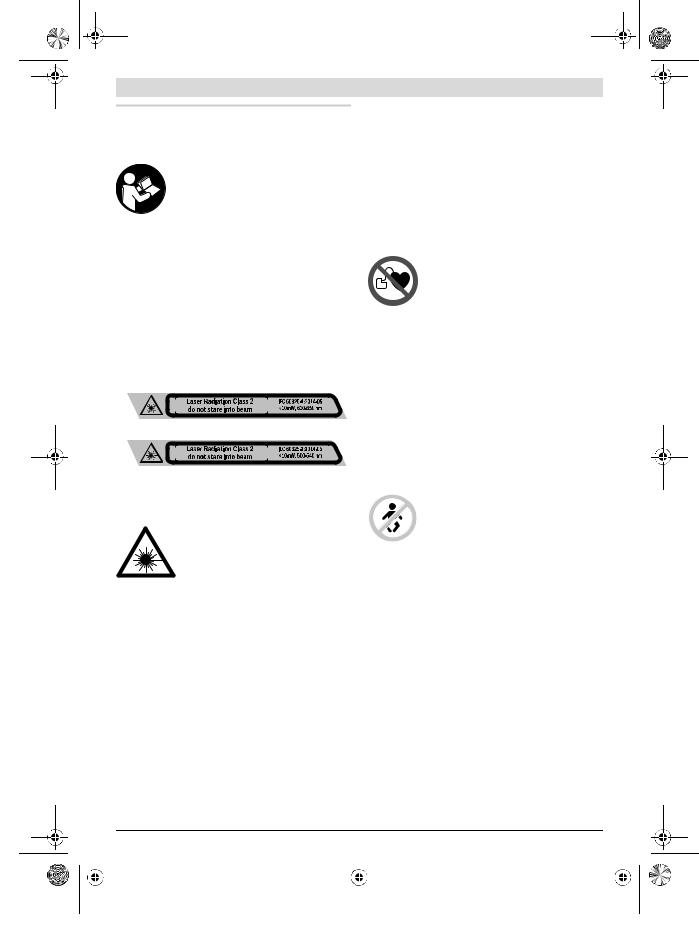
Das Messwerkzeug wird mit einem Warnschild ausgeliefert (in der Darstellung des Messwerkzeugs auf der Grafikseite mit Nummer 20 gekennzeichnet).
GLL 3-80 C
GLL 3-80 CG
Ist der Text des Warnschildes nicht in Ihrer Landessprache, dann überkleben Sie ihn vor der ersten Inbetriebnahme mit dem mitgelieferten Aufkleber in Ihrer Landessprache.
Richten Sie den Laserstrahl nicht auf Personen oder Tiere und blicken Sie nicht selbst in den direkten oder reflektierten Laserstrahl. Dadurch können Sie Personen blenden, Unfälle verursachen oder das Auge schädigen.
Falls Laserstrahlung ins Auge trifft, sind die Augen bewusst zu schließen und der Kopf sofort aus dem Strahl zu bewegen.
Nehmen Sie keine Änderungen an der Lasereinrichtung vor.
Verwenden Sie die Laser-Sichtbrille nicht als Schutzbrille. Die Laser-Sichtbrille dient zum besseren Erkennen des Laserstrahls, sie schützt jedoch nicht vor der Laserstrahlung.
Verwenden Sie die Laser-Sichtbrille nicht als Sonnenbrille oder im Straßenverkehr. Die Laser-Sichtbrille bietet keinen vollständigen UV-Schutz und vermindert die Farbwahrnehmung.
Lassen Sie das Messwerkzeug von qualifiziertem Fachpersonal und nur mit Original-Ersatzteilen reparieren.
Damit wird sichergestellt, dass die Sicherheit des Messwerkzeuges erhalten bleibt.
Deutsch | 7
Lassen Sie Kinder das Laser-Messwerkzeug nicht unbeaufsichtigt benutzen. Sie könnten unbeabsichtigt Personen blenden.
Arbeiten Sie mit dem Messwerkzeug nicht in explosionsgefährdeter Umgebung, in der sich brennbare Flüssigkeiten, Gase oder Stäube befinden. Im Messwerkzeug können Funken erzeugt werden, die den Staub oder die Dämpfe entzünden.
Beim Betrieb des Messwerkzeugs ertönen unter bestimmten Bedingungen laute Signaltöne. Halten Sie deshalb das Messwerkzeug vom Ohr bzw. von anderen Personen fern. Der laute Ton kann das Gehör schädigen.
Bringen Sie das Messwerkzeug, die LaserZieltafel 27 und die universelle Halterung 24 nicht in die Nähe von Herzschrittmachern. Durch die Magnete des Messwerkzeugs, der Laser-Zieltafel und der universellen Halterung wird ein Feld erzeugt, das die Funktion von Herzschrittmachern beeinträchtigen kann.
Halten Sie das Messwerkzeug, die Laser-Zieltafel 27 und die universelle Halterung 24 fern von magnetischen Datenträgern und magnetisch empfindlichen Geräten. Durch die Wirkung der Magnete des Messwerkzeugs, der Laser-Zieltafel und der universellen Halterung kann es zu irreversiblen Datenverlusten kommen.
Bitte beachten Sie, dass das Messwerkzeug mit einer Knopfzelle betrieben wird. Schlucken Sie niemals Knopfzellen. Ein Verschlucken der Knopfzelle kann innerhalb von 2 Stunden zu ernsthaften inneren Verätzungen und zum Tod führen.
Stellen Sie sicher, dass die Knopfzelle nicht in die Hände von Kindern gelangt. Wenn der Verdacht besteht, dass die Knopfzelle verschluckt oder in eine andere Körperöffnung eingeführt wurde, suchen Sie sofort einen Arzt auf.
Benutzen Sie das Messwerkzeug nicht mehr, wenn sich dieKnopfzellen-Halterung22nichtmehrschließenlässt.
Entfernen Sie die Knopfzelle und lassen Sie es reparieren.
Achten Sie beim Batteriewechsel auf den sachgemäßen Austausch der Batterie. Es besteht Explosionsgefahr.
Versuchen Sie nicht, die Knopfzellen wieder aufzuladen, und schließen Sie die Knopfzelle nicht kurz. Die Knopfzelle kann undicht werden, explodieren, brennen und Personen verletzen.
Entfernen und entsorgen Sie entladene Knopfzellen ordnungsgemäß. Entladene Knopfzellen können undicht werden und dadurch das Messwerkzeug beschädigen oder Personen verletzen.
Überhitzen Sie die Knopfzelle nicht und werfen Sie sie nicht ins Feuer. Die Knopfzelle kann undicht werden, explodieren, brennen und Personen verletzen.
Beschädigen Sie die Knopfzelle nicht und nehmen Sie die Knopfzelle nicht auseinander. Die Knopfzelle kann undicht werden, explodieren, brennen und Personen verletzen.
|
Bosch Power Tools |
|
|
1 609 92A 3PX | (2.6.17) |
|||
|
|
|
|
|
|
|
|
|
|
|
|
|
|
|
|
|
|
|
|
|
|
|
|
OBJ_BUCH-3106-001.book Page 8 Friday, June 2, 2017 10:18 AM
8 | Deutsch
Bringen Sie eine beschädigte Knopfzelle nicht in Kontakt mit Wasser. Austretendes Lithium kann mit Wasser Wasserstoff erzeugen und damit zu einem Brand, einer Explosion oder zur Verletzung von Personen führen.
Nehmen Sie den Akku bzw. die Batterien vor allen Arbeiten am Messwerkzeug (z.B. Montage, Wartung etc.) sowie bei dessen Transport und Aufbewahrung aus dem Messwerkzeug. Bei unbeabsichtigtem Betätigen des Ein-/Ausschalters besteht Verletzungsgefahr.
Öffnen Sie den Akku nicht. Es besteht die Gefahr eines Kurzschlusses.
Schützen Sie den Akku vor Hitze, z.B. auch vor dauernder Sonneneinstrahlung, Feuer, Wasser und Feuchtigkeit. Es besteht Explosionsgefahr.
Halten Sie den nicht benutzten Akku fern von Büroklammern, Münzen, Schlüsseln, Nägeln, Schrauben oder anderen kleinen Metallgegenständen, die eine Überbrückung der Kontakte verursachen könnten. Ein Kurzschluss zwischen den Akkukontakten kann Verbrennungen oder Feuer zur Folge haben.
Bei falscher Anwendung kann Flüssigkeit aus dem Akku austreten. Vermeiden Sie den Kontakt damit. Bei zufälligem Kontakt mit Wasser abspülen. Wenn die Flüssigkeit in die Augen kommt, nehmen Sie zusätzlich ärztliche Hilfe in Anspruch. Austretende Akkuflüssigkeit kann zu Hautreizungen oder Verbrennungen führen.
Bei Beschädigung und unsachgemäßem Gebrauch des Akkus können Dämpfe austreten. Führen Sie Frischluft zu und suchen Sie bei Beschwerden einen Arzt auf. Die Dämpfe können die Atemwege reizen.
Laden Sie die Akkus nur mit Ladegeräten auf, die vom Hersteller empfohlen werden. Durch ein Ladegerät, das für eine bestimmte Art von Akkus geeignet ist, besteht Brandgefahr, wenn es mit anderen Akkus verwendet wird.
Verwenden Sie den Akku nur in Verbindung mit Ihrem Bosch-Produkt. Nur so wird der Akku vor gefährlicher Überlastung geschützt.
Durch spitze Gegenstände wie z.B. Nagel oder Schraubenzieher oder durch äußere Krafteinwirkung kann der Akku beschädigt werden. Es kann zu einem internen Kurzschluss kommen und der Akku brennen, rauchen, explodieren oder überhitzen.
Vorsicht! Bei der Verwendung des Messwerkzeugs mit Bluetooth® kann eine Störung anderer Geräte und Anlagen, Flugzeuge und medizinischer Geräte (z.B. Herzschrittmacher, Hörgeräte) auftreten. Ebenfalls kann eine Schädigung von Menschen und Tieren in unmittel-
barer Umgebung nicht ganz ausgeschlossen werden. Verwenden Sie das Messwerkzeug mit Bluetooth® nicht in der Nähe von medizinischen Geräten, Tankstellen, chemischen Anlagen, Gebieten mit Explosions-
gefahr und in Sprenggebieten. Verwenden Sie das Messwerkzeug mit Bluetooth® nicht in Flugzeugen.
Vermeiden Sie den Betrieb über einen längeren Zeitraum in direkter Körpernähe.
Produktund Leistungsbeschreibung
Bitte klappen Sie die Ausklappseite mit der Darstellung des Messwerkzeugs auf, und lassen Sie diese Seite aufgeklappt, während Sie die Betriebsanleitung lesen.
Die Bluetooth®-Wortmarke wie auch die Bildzeichen
(Logos) sind eingetragene Warenzeichen und Eigentum der Bluetooth SIG, Inc. Jegliche Verwendung dieser Wortmarke/Bildzeichen durch die Robert Bosch Power Tools GmbH erfolgt unter Lizenz.
Bestimmungsgemäßer Gebrauch
Das Messwerkzeug ist bestimmt zum Ermitteln und Überprüfen von waagrechten und senkrechten Linien.
Abgebildete Komponenten
Die Nummerierung der abgebildeten Komponenten bezieht sich auf die Darstellung des Messwerkzeugs auf der Grafikseite.
1Austrittsöffnung Laserstrahlung
2Ladezustand Akku/Batterien
3Anzeige CAL guard
4Anzeige Arbeiten ohne Nivellierautomatik
5Taste Empfängermodus
6Anzeige Empfängermodus
7Taste für Laser-Betriebsart
8Anzeige Bluetooth®-Verbindung
9Bluetooth®-Taste 
10Akkuschacht
11Hülle Batterieadapter*
12Batterien*
13Entriegelungstaste Akku/Batterieadapter*
14Verschlusskappe Batterieadapter*
15Akku*
16Ein-/Ausschalter
17Stativaufnahme 1/4"
18Stativaufnahme 5/8"
19Seriennummer
20Laser-Warnschild
21Knopfzelle
22Knopfzellen-Halterung
23Knopfzellen-Schacht
24Universelle Halterung*
25Drehplattform*
26Laserempfänger*
27Laser-Zieltafel*
28Laser-Sichtbrille*
29Schutztasche*
30Stativ*
31Teleskopstange*
32Koffer*
33Einlage*
*Abgebildetes oder beschriebenes Zubehör gehört nicht zum Standard-Lieferumfang.
|
1 609 92A 3PX | (2.6.17) |
|
|
Bosch Power Tools |
|||
|
|
|
|
|
|
|
|
|
|
|
|
|
|
|
|
|
|
|
|
|
|
|
|
OBJ_BUCH-3106-001.book Page 9 Friday, June 2, 2017 10:18 AM
|
|
Deutsch | 9 |
Technische Daten |
|
|
|
|
|
Linienlaser |
GLL 3-80 C |
GLL 3-80 CG |
Sachnummer |
3 601 K63 R.. |
3 601 K63 T.. |
Arbeitsbereich1) |
|
|
– Standard |
30 m |
30 m |
– im Empfängermodus |
25 m |
25 m |
– mit Laserempfänger |
5–120 m |
5–120 m |
Nivelliergenauigkeit typisch |
±0,2 mm/m |
±0,2 mm/m |
Selbstnivellierbereich typisch |
±4° |
±4° |
Nivellierzeit typisch |
<4 s |
<4 s |
Relative Luftfeuchte max. |
90 % |
90 % |
Laserklasse |
2 |
2 |
Lasertyp |
630–650 nm, <10 mW |
500–540 nm, <10 mW |
C6 |
10 |
10 |
Divergenz Laserlinie |
50 x 10 mrad (Vollwinkel) |
50 x 10 mrad (Vollwinkel) |
kürzeste Impulsdauer |
1/10000 s |
1/10000 s |
kompatible Laserempfänger |
LR6, LR7 |
LR7 |
Stativaufnahme |
1/4", 5/8" |
1/4", 5/8" |
Energieversorgung Messwerkzeug |
|
|
– Akku (Li-Ionen) |
10,8 V/12 V |
10,8 V/12 V |
– Batterien (Alkali-Mangan) |
4 x 1,5 V LR6 (AA) (mit Batterieadapter) |
4 x 1,5 V LR6 (AA) (mit Batterieadapter) |
Betriebsdauer mit 3 Laserebenen2) |
|
|
– mit Akku |
8 h |
6 h |
– mit Batterien |
6 h |
4 h |
Bluetooth®-Messwerkzeug |
Bluetooth® 4.0 (Low Energy)3) |
Bluetooth® 4.0 (Low Energy)3) |
– Kompatibilität |
||
– Signalreichweite max. |
30 m4) |
30 m4) |
– genutzter Frequenzbereich |
2402–2480 MHz |
2402–2480 MHz |
– Ausgangsleistung |
<1 mW |
<1 mW |
Bluetooth®-Smartphone |
Bluetooth® 4.0 (Low Energy)3) |
Bluetooth® 4.0 (Low Energy)3) |
– Kompatibilität |
||
– Betriebssystem |
Android 4.3 (und höher) |
Android 4.3 (und höher) |
|
iOS 7 (und höher) |
iOS 7 (und höher) |
Gewicht entsprechend |
|
|
EPTA-Procedure 01:2014 |
0,90 kg |
0,90 kg |
– mit Akku |
||
– mit Batterien |
0,86 kg |
0,86 kg |
Maße (Länge x Breite x Höhe) |
162 x 84 x 148 mm |
162 x 84 x 148 mm |
Schutzart |
IP 54 (staubund spritzwassergeschützt) |
IP 54 (staubund spritzwassergeschützt) |
erlaubte Umgebungstemperatur |
|
|
– beim Laden |
0 °C...+45 °C |
0 °C...+45 °C |
– beim Betrieb5) |
–10 °C...+40 °C |
–10 °C...+40 °C |
– bei Lagerung |
–20 °C...+70 °C |
–20 °C...+70 °C |
1)Der Arbeitsbereich kann durch ungünstige Umgebungsbedingungen (z.B. direkte Sonneneinstrahlung) verringert werden.
2)Kürzere Betriebszeiten bei Bluetooth®-Betrieb und/oder in Verbindung mit RM 3.
3)Bei Bluetooth®-Low-Energy-Geräten kann je nach Modell und Betriebssystem kein Verbindungsaufbau möglich sein. Bluetooth®-Geräte müssen das SPP-Profil unterstützen.
4)Die Reichweite kann je nach äußeren Bedingungen, einschließlich des verwendeten Empfangsgeräts, stark variieren. Innerhalb von geschlossenen Räumen und durch metallische Barrieren (z. B. Wände, Regale, Koffer etc.) kann die Bluetooth®-Reichweite deutlich geringer sein.
5)eingeschränkte Leistung bei Temperaturen <0 °C
Technische Daten ermittelt mit Akku aus Lieferumfang.
Zur eindeutigen Identifizierung Ihres Messwerkzeugs dient die Seriennummer 19 auf dem Typenschild.
|
Bosch Power Tools |
|
|
1 609 92A 3PX | (2.6.17) |
|||
|
|
|
|
|
|
|
|
|
|
|
|
|
|
|
|
|
|
|
|
|
|
|
|
OBJ_BUCH-3106-001.book Page 10 Friday, June 2, 2017 10:18 AM
10 | Deutsch
Linienlaser |
GLL 3-80 C |
GLL 3-80 CG |
empfohlene Akkus |
GBA 10,8V ... |
GBA 10,8V ... |
|
GBA 12V ... |
GBA 12V ... |
|
außer GBA 12V 4,0 Ah |
außer GBA 12V 4,0 Ah |
empfohlene Ladegeräte |
AL 11.. CV |
AL 11.. CV |
|
GAL 12.. CV |
GAL 12.. CV |
1)Der Arbeitsbereich kann durch ungünstige Umgebungsbedingungen (z.B. direkte Sonneneinstrahlung) verringert werden.
2)Kürzere Betriebszeiten bei Bluetooth®-Betrieb und/oder in Verbindung mit RM 3.
3)Bei Bluetooth®-Low-Energy-Geräten kann je nach Modell und Betriebssystem kein Verbindungsaufbau möglich sein. Bluetooth®-Geräte müssen das SPP-Profil unterstützen.
4)Die Reichweite kann je nach äußeren Bedingungen, einschließlich des verwendeten Empfangsgeräts, stark variieren. Innerhalb von geschlossenen Räumen und durch metallische Barrieren (z. B. Wände, Regale, Koffer etc.) kann die Bluetooth®-Reichweite deutlich geringer sein.
5)eingeschränkte Leistung bei Temperaturen <0 °C
Technische Daten ermittelt mit Akku aus Lieferumfang.
Zur eindeutigen Identifizierung Ihres Messwerkzeugs dient die Seriennummer 19 auf dem Typenschild.
Montage
Energieversorgung Messwerkzeug
Das Messwerkzeug kann entweder mit handelsüblichen Batterien oder mit einem Bosch Li-Ionen-Akku betrieben werden.
Betrieb mit Akku
Hinweis: Der Gebrauch von nicht für Ihr Messwerkzeug geeigneten Akkus kann zu Fehlfunktionen oder zur Beschädigung des Messwerkzeugs führen.
Hinweis: Der Akku wird teilgeladen ausgeliefert. Um die volle Leistung des Akkus zu gewährleisten, laden Sie vor dem ersten Einsatz den Akku vollständig im Ladegerät auf.
Benutzen Sie nur die in den technischen Daten aufgeführten Ladegeräte. Nur diese Ladegeräte sind auf den bei Ihrem Messwerkzeug verwendbaren Li-Ionen-Akku abgestimmt.
Der Li-Ionen-Akku kann jederzeit aufgeladen werden, ohne die Lebensdauer zu verkürzen. Eine Unterbrechung des Ladevorganges schädigt den Akku nicht.
Der Li-Ionen-Akku ist durch die „Electronic Cell Protection (ECP)“ gegen Tiefentladung geschützt. Bei entladenem Akku wird das Messwerkzeug durch eine Schutzschaltung abgeschaltet.
Schalten Sie das Messwerkzeug nicht wieder ein, nachdem es durch die Schutzschaltung abgeschaltet wurde.
Der Akku kann beschädigt werden.
Zum Einsetzen des geladenen Akkus 15 schieben Sie diesen in den Akkuschacht, bis er spürbar einrastet.
Zum Entnehmen des Akkus 15 drücken Sie die Entriegelungstasten 13 und ziehen den Akku aus dem Akkuschacht
10. Wenden Sie dabei keine Gewalt an.
Betrieb mit Batterien
Für den Betrieb des Messwerkzeugs wird die Verwendung von Alkali-Mangan-Batterien empfohlen.
Die Batterien werden in den Batterieadapter eingesetzt.
Der Batterieadapter ist ausschließlich zum Gebrauch in dafür vorgesehenen Bosch-Messwerkzeugen bestimmt und darf nicht mit Elektrowerkzeugen verwendet werden.
Zum Einsetzen der Batterien schieben Sie die Hülle 11 des Batterieadapters in den Akkuschacht 10. Legen Sie die Batterien entsprechend der Abbildung auf der Verschlusskappe 14 in die Hülle ein. Schieben Sie die Verschlusskappe über die Hülle, bis diese spürbar einrastet.
Zum Entnehmen der Batterien 12 drücken Sie die Entriegelungstasten 13 der Verschlusskappe 14
und ziehen die Verschlusskappe ab. Achten Sie da-
bei darauf, dass die Batterien nicht herausfallen.
Halten Sie das Messwerkzeug dazu mit dem Akkuschacht 10 nach oben gerichtet. Entnehmen Sie
die Batterien. Um die innen liegende Hülle 11 aus dem Akkuschacht 10 zu entfernen, greifen Sie in die Hülle und ziehen diese bei leichtem Druck auf die Seitenwand aus dem Messwerkzeug heraus.
Ersetzen Sie immer alle Batterien gleichzeitig. Verwenden Sie nur Batterien eines Herstellers und mit gleicher Kapazität.
Nehmen Sie die Batterien aus dem Messwerkzeug, wenn Sie es längere Zeit nicht benutzen. Die Batterien können bei längerer Lagerung korrodieren und sich selbst entladen.
Ladezustandsanzeige
Die Ladezustandsanzeige 2 zeigt den Ladezustand des Akkus bzw. der Batterien an:
LED |
Ladezustand |
Dauerlicht grün |
100–75 % |
Dauerlicht gelb |
75–35 % |
Dauerlicht rot |
35–10 % |
Kein Licht |
– Akku defekt |
|
– Batterien leer |
Werden der Akku bzw. die Batterien schwach, wird die Helligkeit der Laserlinien langsam verringert.
Tauschen Sie einen defekten Akku oder leere Batterien umgehend aus.
|
1 609 92A 3PX | (2.6.17) |
|
|
Bosch Power Tools |
|||
|
|
|
|
|
|
|
|
|
|
|
|
|
|
|
|
|
|
|
|
|
|
|
|
OBJ_BUCH-3106-001.book Page 11 Friday, June 2, 2017 10:18 AM
Betrieb
Inbetriebnahme
Schützen Sie das Messwerkzeug vor Nässe und direkter Sonneneinstrahlung.
Setzen Sie das Messwerkzeug keinen extremen Temperaturen oder Temperaturschwankungen aus. Lassen Sie es z.B. nicht längere Zeit im Auto liegen. Lassen Sie das MesswerkzeugbeigrößerenTemperaturschwankungenerst austemperieren, bevor Sie es in Betrieb nehmen. Bei extremen Temperaturen oder Temperaturschwankungen kann die Präzision des Messwerkzeugs beeinträchtigt werden.
Vermeiden Sie heftige Stöße oder Stürze des Messwerkzeuges. Nach starken äußeren Einwirkungen auf das Messwerkzeug sollten Sie vor dem Weiterarbeiten immer eine Genauigkeitsüberprüfung durchführen (siehe „Genauigkeitsüberprüfung des Messwerkzeugs“, Seite 12).
Schalten Sie das Messwerkzeug aus, wenn Sie es transportieren. Beim Ausschalten wird die Pendeleinheit verriegelt, die sonst bei starken Bewegungen beschädigt werden kann.
Ein-/Ausschalten
Zum Einschalten des Messwerkzeugs schieben Sie den Ein-/Ausschalter 16 in die Position „ On“ (für Arbeiten ohne Nivellierautomatik) oder in die Position „
 On“ (für Arbeiten mit Nivellierautomatik). Das Messwerkzeug sendet sofort nach dem Einschalten Laserlinien aus den Austrittsöffnungen 1.
Richten Sie den Laserstrahl nicht auf Personen oder Tiere und blicken Sie nicht selbst in den Laserstrahl, auch nicht aus größerer Entfernung.
Zum Ausschalten des Messwerkzeugs schieben Sie den Ein-/ Ausschalter 16 in Position „Off“. Beim Ausschalten wird die Pendeleinheit verriegelt.
Lassen Sie das eingeschaltete Messwerkzeug nicht unbeaufsichtigt und schalten Sie das Messwerkzeug nach Gebrauch ab. Andere Personen könnten vom Laserstrahl geblendet werden.
Bei Überschreiten der höchstzulässigen Betriebstemperatur von 40 °C erfolgt die Abschaltung zum Schutz der Laserdiode. Nach dem Abkühlen ist das Messwerkzeug wieder betriebsbereit und kann erneut eingeschaltet werden.
Nähert sich die Temperatur des Messwerkzeugs der höchstzulässigen Betriebstemperatur, wird die Helligkeit der Laserlinien langsam verringert.
Abschaltautomatik deaktivieren
Wird ca. 120 min lang keine Taste am Messwerkzeug gedrückt, schaltet sich das Messwerkzeug zur Schonung der Batterien automatisch ab.
Um das Messwerkzeug nach der automatischen Abschaltung wieder einzuschalten, können Sie entweder den Ein-/Aus- schalter 16 erst in Position „Off“ schieben und das Messwerkzeug dann wieder einschalten, oder Sie drücken einmal die Taste Laser-Betriebsart 7 oder die Taste Empfängermodus 5.
Deutsch | 11
Um die Abschaltautomatik zu deaktivieren, halten Sie (bei eingeschaltetem Messwerkzeug) die Taste Laser-Betriebsart 7 mindestens 3 s lang gedrückt. Ist die Abschaltautomatik deaktiviert, blinken die Laserstrahlen kurz zur Bestätigung.
Um die automatische Abschaltung zu aktivieren, schalten Sie das Messwerkzeug aus und wieder ein.
Signalton deaktivieren
Nach dem Einschalten des Messwerkzeugs ist der Signalton immer aktiviert.
Zum Deaktivieren bzw. Aktivieren des Signaltons drücken Sie gleichzeitig die Taste Laser-Betriebsart 7 und die Taste Empfängermodus 5 und halten sie mindestens 3 s gedrückt.
Sowohl beim Aktivieren als auch beim Deaktivieren ertönen drei kurze Signaltöne zur Bestätigung.
Betriebsarten
Das Messwerkzeug verfügt über mehrere Betriebsarten, zwischen denen Sie jederzeit wechseln können:
–Erzeugen einer waagrechten Laserebene,
–Erzeugen einer senkrechten Laserebene,
–Erzeugen von zwei senkrechten Laserebenen,
–Erzeugen einer waagrechten Laserebene sowie von zwei senkrechten Laserebenen.
Nach dem Einschalten erzeugt das Messwerkzeug eine waagrechte Laserebene. Um die Betriebsart zu wechseln, drücken Sie die Taste Laser-Betriebsart 7.
Alle Betriebsarten können sowohl mit als auch ohne Nivellierautomatik gewählt werden.
Empfängermodus
Für das Arbeiten mit dem Laserempfänger 26 muss – unabhängig von der gewählten Betriebsart – der Empfängermodus aktiviert werden.
Im Empfängermodus blinken die Laserlinien mit sehr hoher Frequenz und werden dadurch für den Laserempfänger 26 auffindbar.
Zum Einschalten des Empfängermodus drücken Sie die Taste 5. Die Anzeige 6 leuchtet grün.
Für das menschliche Auge ist die Sichtbarkeit der Laserlinien bei eingeschaltetem Empfängermodus verringert. Für Arbeiten ohne Laserempfänger schalten Sie deshalb den Empfängermodus durch erneutes Drücken der Taste 5 aus. Die Anzeige 6 erlischt.
Nivellierautomatik
Arbeiten mit Nivellierautomatik
Stellen Sie das Messwerkzeug auf eine waagerechte, feste Unterlage, befestigen Sie es auf der Halterung 24 oder dem Stativ 30.
Schieben Sie für Arbeiten mit Nivellierautomatik den Ein-/Aus- schalter 16 in Position „ On“.
On“.
Die Nivellierautomatik gleicht Unebenheiten innerhalb des Selbstnivellierbereiches von ±4° automatisch aus. Die Nivellierung ist abgeschlossen, sobald sich die Laserlinien nicht mehr bewegen.
|
Bosch Power Tools |
|
|
1 609 92A 3PX | (2.6.17) |
|||
|
|
|
|
|
|
|
|
|
|
|
|
|
|
|
|
|
|
|
|
|
|
|
|

OBJ_BUCH-3106-001.book Page 12 Friday, June 2, 2017 10:18 AM
12 | Deutsch
Ist die automatische Nivellierung nicht möglich, z.B. weil die Standfläche des Messwerkzeugs mehr als 4° von der Waagerechten abweicht, beginnen die Laserlinien in schnellem Takt zu blinken. Bei aktiviertem Signalton ertönt ein Signalton in schnellem Takt.
Stellen Sie das Messwerkzeug waagerecht auf und warten Sie die Selbstnivellierung ab. Sobald sich das Messwerkzeug innerhalb des Selbstnivellierbereiches von ±4° befindet, leuchten die Laserstrahlen dauerhaft und der Signalton wird abgeschaltet.
Bei Erschütterungen oder Lageänderungen während des Betriebs wird das Messwerkzeug automatisch wieder einnivelliert. Überprüfen Sie nach einer erneuten Nivellierung die Position der waagrechten bzw. senkrechten Laserlinie in Bezug auf Referenzpunkte, um Fehler zu vermeiden.
Arbeiten ohne Nivellierautomatik
Schieben Sie für Arbeiten ohne Nivellierautomatik den Ein-/Ausschalter 16 in Position „ On“. Bei ausgeschalteter Nivellierautomatik leuchtet die Anzeige 4 rot und die Laserlinien blinken dauerhaft in langsamem Takt.
Bei abgeschalteter Nivellierautomatik können Sie das Messwerkzeug frei in der Hand halten oder auf eine geneigte Unterlage stellen. Die Laserlinien verlaufen nicht mehr zwingend senkrecht zueinander.
Fernsteuerung über „Levelling Remote App“
Das Messwerkzeug ist mit einem Bluetooth®-Modul ausge-
stattet, das mittels Funktechnik die Fernsteuerung über ein Smartphone mit Bluetooth®-Schnittstelle erlaubt.
Zur Nutzung dieser Funktion wird die Applikation (App) „Levelling Remote App“ benötigt. Diese können Sie je nach Endgerät in einem entsprechenden App-Store (Apple App Store, Google Play Store) herunterladen.
Informationen zur erforderlichen Systemvoraussetzung für eine Bluetooth®-Verbindung finden Sie auf der Bosch-Inter-
netseite unter www.bosch-pt.de
Bei der Fernsteuerung mittels Bluetooth® können durch schlechte Empfangsbedingungen Zeitverzögerungen zwischen mobilem Endgerät und Messwerkzeug auftreten.
Bluetooth® einschalten
Um Bluetooth® für die Fernsteuerung einzuschalten, drücken Sie die Bluetooth®-Taste 9. Stellen Sie sicher, dass die Blue-
tooth®-Schnittstelle an Ihrem mobilen Endgerät aktiviert ist.
Nach dem Start der Bosch-Applikation wird die Verbindung zwischen mobilem Endgerät und Messwerkzeug hergestellt. Werden mehrere aktive Messwerkzeuge gefunden, wählen Sie das passende Messwerkzeug aus. Wird nur ein aktives Messwerkzeug gefunden, findet ein automatischer Verbindungsaufbau statt.
Die Verbindung ist aufgebaut, sobald die Bluetooth®-Anzeige 8 leuchtet.
Die Bluetooth®-Verbindung kann wegen zu großer Distanz oder Hindernissen zwischen Messwerkzeug und mobilem
Endgerät sowie durch elektromagnetische Störquellen unterbrochen werden. In diesem Fall blinkt die Bluetooth®-Anzeige.
Bluetooth® ausschalten
Um Bluetooth® für die Fernsteuerung auszuschalten, drücken Sie die Bluetooth®-Taste 9 oder schalten Sie das Messwerk-
zeug aus.
Kalibrierwarnung CAL guard
Die Sensoren der Kalibrierwarnung CAL guard überwachen den Zustand des Messwerkzeugs, auch wenn es ausgeschaltet ist. Ist das Messwerkzeug ohne Energieversorgung durch Akku oder Batterien, sorgt ein interner Energiespeicher für 72 Stunden für eine kontinuierliche Überwachung durch die Sensoren.
Die Sensoren werden mit der ersten Inbetriebnahme des Messwerkzeugs aktiviert.
Auslöser der Kalibrierwarnung
Wenn eines der folgenden Ereignisse eintritt, wird die Kalibrierwarnung CAL guard ausgelöst und die Anzeige 3 leuchtet rot auf:
–Das Kalibrierintervall (alle 12 Monate) ist abgelaufen.
–Das Messwerkzeug wurde außerhalb des Lagertemperaturbereichs gelagert.
–Das Messwerkzeug wurde einer massiven Erschütterung ausgesetzt (z.B. Aufprall auf den Boden nach einem Sturz).
In der „Levelling Remote App“ können Sie sehen, welches der drei Ereignisse die Kalibrierwarnung ausgelöst hat. Ohne die App ist diese Ursache nicht erkennbar, das Aufleuchten der Anzeige CAL guard 3 teilt ausschließlich mit, dass die Nivelliergenauigkeit überprüft werden muss.
Nach dem Auslösen der Warnung leuchtet die Anzeige
CAL guard 3 so lange, bis die Nivelliergenauigkeit überprüft und die Anzeige danach ausgeschaltet wird.
Vorgehen bei ausgelöster Kalibrierwarnung
Überprüfen Sie die Nivelliergenauigkeit des Messwerkzeugs (siehe „Genauigkeitsüberprüfung des Messwerkzeugs“, Seite 12).
Wird die maximale Abweichung bei keiner der Prüfungen überschritten, dann schalten Sie die Anzeige CAL guard 3
aus. Drücken Sie dazu die Taste Empfängermodus 5 und die Bluetooth®-Taste 9 gleichzeitig für mindestens 3 s. Die An-
zeige CAL guard 3 erlischt.
Sollte das Messwerkzeug bei einer der Prüfungen die maximale Abweichung überschreiten, dann lassen Sie es von einem Bosch-Kundendienst reparieren.
Genauigkeitsüberprüfung des Messwerkzeugs
Genauigkeitseinflüsse
Den größten Einfluss übt die Umgebungstemperatur aus. Besonders vom Boden nach oben verlaufende Temperaturunterschiede können den Laserstrahl ablenken.
Da die Temperaturschichtung in Bodennähe am größten ist, sollten Sie das Messwerkzeug ab einer Messstrecke von 20 m immer auf einem Stativ montieren. Stellen Sie das Messwerkzeug außerdem nach Möglichkeit in der Mitte der Arbeitsfläche auf.
|
1 609 92A 3PX | (2.6.17) |
|
|
Bosch Power Tools |
|||
|
|
|
|
|
|
|
|
|
|
|
|
|
|
|
|
|
|
|
|
|
|
|
|
OBJ_BUCH-3106-001.book Page 13 Friday, June 2, 2017 10:18 AM
Neben äußeren Einflüssen können auch gerätespezifische Einflüsse (wie z.B. Stürze oder heftige Stöße) zu Abweichungen führen. Überprüfen Sie deshalb vor jedem Arbeitsbeginn die Nivelliergenauigkeit.
Überprüfen Sie jeweils zuerst die Nivelliergenauigkeit der waagrechten Laserlinie und danach die Nivelliergenauigkeit der senkrechten Laserlinien.
Sollte das Messwerkzeug bei einer der Prüfungen die maximale Abweichung überschreiten, dann lassen Sie es von einem Bosch-Kundendienst reparieren.
Waagerechte Nivelliergenauigkeit der Querachse überprüfen
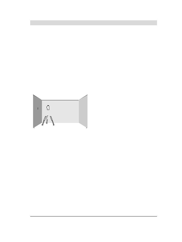
Für die Überprüfung benötigen Sie eine freie Messstrecke von 5 m auf festem Grund zwischen zwei Wänden A und B.
–Montieren Sie das Messwerkzeug nahe der Wand A auf einem Stativ oder stellen Sie es auf festen, ebenen Untergrund. Schalten Sie das Messwerkzeug im Betrieb mit Nivellierautomatik ein. Wählen Sie die Betriebsart, in der eine waagrechte Laserebene sowie eine senkrechte Laserebene frontal vor dem Messwerkzeug erzeugt werden.
A 

 B
B
5m
–Richten Sie den Laser auf die nahe Wand A und lassen Sie das Messwerkzeug einnivellieren. Markieren Sie die Mitte des Punktes, an dem sich die Laserlinien an der Wand A kreuzen (Punkt I).
A |
|
|
|
B |
180° |
||||
|
|
|
|
|
|
|
|
|
|
|
|
|
|
|
–Drehen Sie das Messwerkzeug um 180°, lassen Sie es einnivellieren und markieren Sie den Kreuzungspunkt der Laserlinien an der gegenüberliegenden Wand B (Punkt II).
Deutsch | 13
–Platzieren Sie das Messwerkzeug – ohne es zu drehen – nahe der Wand B, schalten Sie es ein und lassen Sie es einnivellieren.
A  B
B
–Richten Sie das Messwerkzeug in der Höhe so aus (mithilfe des Stativs oder gegebenenfalls durch Unterlegen), dass der Kreuzungspunkt der Laserlinien genau den zuvor markierten Punkt II auf der Wand B trifft.
A |
|
B |
||
180° |
||||
|
|
|
||
d |
|
|
|
|
|
|
|
|
|
–Drehen Sie das Messwerkzeug um 180°, ohne die Höhe zu verändern. Richten Sie es so auf die Wand A, dass die senkrechte Laserlinie durch den bereits markierten Punkt I läuft. Lassen Sie das Messwerkzeug einnivellieren und markieren Sie den Kreuzungspunkt der Laserlinien auf der Wand A (Punkt III).
–Die Differenz d der beiden markierten Punkte I und III auf der Wand A ergibt die tatsächliche Höhenabweichung des Messwerkzeugs entlang der Querachse.
Auf der Messstrecke von 2 x 5 m = 10 m beträgt die maximal zulässige Abweichung:
10 m x ±0,2 mm/m = ±2 mm.
Die Differenz d zwischen den Punkten I und III darf folglich höchstens 2 mm betragen.
Nivelliergenauigkeit der senkrechten Linien überprüfen
Für die Überprüfung benötigen Sie eine Türöffnung, bei der (auf festem Grund) auf jeder Seite der Tür mindestens 2,5 m Platz sind.
–Stellen Sie das Messwerkzeug in 2,5 m Entfernung von der Türöffnung auf festem, ebenem Grund auf (nicht auf einem Stativ). Schalten Sie das Messwerkzeug im Betrieb mit Nivellierautomatik ein. Wählen Sie eine Betriebsart, in der eine senkrechte Laserebene frontal vor dem Messwerkzeug erzeugt wird.
|
Bosch Power Tools |
|
|
1 609 92A 3PX | (2.6.17) |
|||
|
|
|
|
|
|
|
|
|
|
|
|
|
|
|
|
|
|
|
|
|
|
|
|
OBJ_BUCH-3106-001.book Page 14 Friday, June 2, 2017 10:18 AM
14 | Deutsch
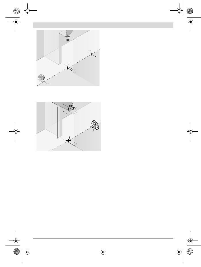
–Markieren Sie die Mitte der senkrechten Laserlinie am Boden der Türöffnung (Punkt I), in 5 m Entfernung auf der anderen Seite der Türöffnung (Punkt II) sowie am oberen Rand der Türöffnung (Punkt III).
<![if ! IE]><![endif]>m2
–Drehen Sie das Messwerkzeug um 180° und stellen Sie es auf der anderen Seite der Türöffnung direkt hinter den Punkt II. Lassen Sie das Messwerkzeug einnivellieren und richten Sie die senkrechte Laserlinie so aus, dass ihre Mitte genau durch die Punkte I und II verläuft.
–Markieren Sie die Mitte der Laserlinie am oberen Rand der Türöffnung als Punkt IV.
–Die Differenz d der beiden markierten Punkte III und IV ergibt die tatsächliche Abweichung des Messwerkzeugs von der Senkrechten.
–Messen Sie die Höhe der Türöffnung.
Wiederholen Sie den Messvorgang für die zweite senkrechte Laserebene. Wählen Sie dazu eine Betriebsart, in der eine senkrechte Laserebene seitlich neben dem Messwerkzeug erzeugt wird, und drehen Sie das Messwerkzeug vor dem Beginn des Messvorganges um 90°.
Die maximale zulässige Abweichung berechnen Sie wie folgt: doppelte Höhe der Türöffnung x 0,2 mm/m
Beispiel: Bei einer Höhe der Türöffnung von 2 m darf die maximale Abweichung
2 x 2 m x ±0,2 mm/m = ±0,8 mm betragen. Die Punkte III und IV dürfen bei jeder der beiden Messungen folglich höchstens 0,8 mm auseinander liegen.
Arbeitshinweise
Verwenden Sie immer nur die Mitte der Laserlinie zum Markieren. Die Breite der Laserlinie ändert sich mit der Entfernung.
Das Messwerkzeug ist mit einer Funkschnittstelle ausgestattet. Lokale Betriebseinschränkungen, z. B. in Flugzeugen oder Krankenhäusern, sind zu beachten.
Arbeiten mit der Laser-Zieltafel
Die Laser-Zieltafel 27 verbessert die Sichtbarkeit des Laserstrahls bei ungünstigen Bedingungen und größeren Entfernungen.
Die reflektierende Hälfte der Laser-Zieltafel 27 verbessert die Sichtbarkeit der Laserlinie, durch die transparente Hälfte ist die Laserlinie auch von der Rückseite der Laser-Zieltafel erkennbar.
Arbeiten mit dem Stativ (Zubehör)
Ein Stativ bietet eine stabile, höheneinstellbare Messunterlage. Setzen Sie das Messwerkzeug mit der 1/4"-Stativauf- nahme 17 auf das Gewinde des Stativs 30 oder eines handelsüblichen Fotostativs. Für die Befestigung auf einem handelsüblichen Baustativ benutzen Sie die 5/8"-Stativauf- nahme 18. Schrauben Sie das Messwerkzeug mit der Feststellschraube des Stativs fest.
Richten Sie das Stativ grob aus, bevor Sie das Messwerkzeug einschalten.
Befestigen mit der universellen Halterung (Zubehör) (siehe Bild B)
Mithilfe der universellen Halterung 24 können Sie das Messwerkzeug z.B. an senkrechten Flächen, Rohren oder magnetisierbaren Materialien befestigen. Die universelle Halterung ist ebenso als Bodenstativ geeignet und erleichtert die Höhenausrichtung des Messwerkzeugs.
Richten Sie die universelle Halterung 24 grob aus, bevor Sie das Messwerkzeug einschalten.
Arbeiten mit Laserempfänger (Zubehör) (siehe Bild B)
Bei ungünstigen Lichtverhältnissen (helle Umgebung, direkte Sonneneinstrahlung) und auf größere Entfernungen verwenden Sie zum besseren Auffinden der Laserlinien den Laserempfänger 26. Schalten Sie beim Arbeiten mit dem Laserempfänger den Empfängermodus ein (siehe „Empfängermodus“, Seite 11).
Laser-Sichtbrille (Zubehör)
Die Laser-Sichtbrille filtert das Umgebungslicht aus. Dadurch erscheint das Licht des Lasers für das Auge heller.
Verwenden Sie die Laser-Sichtbrille nicht als Schutzbrille. Die Laser-Sichtbrille dient zum besseren Erkennen des Laserstrahls, sie schützt jedoch nicht vor der Laserstrahlung.
Verwenden Sie die Laser-Sichtbrille nicht als Sonnenbrille oder im Straßenverkehr. Die Laser-Sichtbrille bietet keinen vollständigen UV-Schutz und vermindert die Farbwahrnehmung.
|
1 609 92A 3PX | (2.6.17) |
|
|
Bosch Power Tools |
|||
|
|
|
|
|
|
|
|
|
|
|
|
|
|
|
|
|
|
|
|
|
|
|
|
OBJ_BUCH-3106-001.book Page 15 Friday, June 2, 2017 10:18 AM
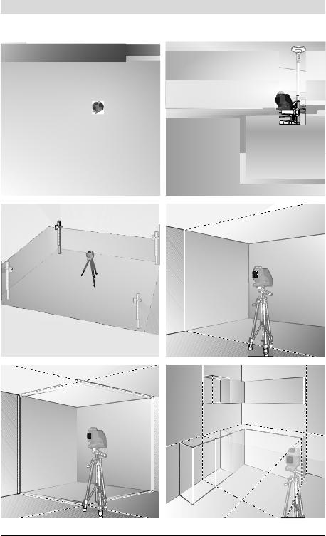
Arbeitsbeispiele (siehe Bilder A – F)
Beispiele für Anwendungsmöglichkeiten des Messwerkzeugs finden Sie auf den Grafikseiten.
Stellen Sie das Messwerkzeug immer nah an die Fläche oder Kante, die überprüft werden soll, und lassen Sie es vor Beginn jeder Messung einnivellieren.
Wartung und Service
Wartung und Reinigung
Lagern und transportieren Sie das Messwerkzeug nur in der mitgelieferten Schutztasche oder dem Koffer.
Halten Sie das Messwerkzeug stets sauber.
Tauchen Sie das Messwerkzeug nicht ins Wasser oder andere Flüssigkeiten.
Wischen Sie Verschmutzungen mit einem feuchten, weichen Tuch ab. Verwenden Sie keine Reinigungsoder Lösemittel.
Reinigen Sie insbesondere die Flächen an der Austrittsöffnung des Lasers regelmäßig und achten Sie dabei auf Fusseln.
Senden Sie im Reparaturfall das Messwerkzeug in der Schutztasche 29 ein.
Kundendienst und Anwendungsberatung
Der Kundendienst beantwortet Ihre Fragen zu Reparatur und Wartung Ihres Produkts sowie zu Ersatzteilen. Explosionszeichnungen und Informationen zu Ersatzteilen finden Sie auch unter:
www.bosch-pt.com
Das Bosch-Anwendungsberatungs-Team hilft Ihnen gerne bei Fragen zu unseren Produkten und deren Zubehör.
www.powertool-portal.de, das Internetportal für Handwerker und Heimwerker.
Geben Sie bei allen Rückfragen und Ersatzteilbestellungen bitte unbedingt die 10-stellige Sachnummer laut Typenschild des Produkts an.
Deutschland
Robert Bosch Power Tools GmbH
Servicezentrum Elektrowerkzeuge Zur Luhne 2
37589 Kalefeld – Willershausen
Unter www.bosch-pt.com können Sie online Ersatzteile bestellen oder Reparaturen anmelden.
Kundendienst: Tel.: (0711) 40040460 Fax: (0711) 40040461
E-Mail: Servicezentrum.Elektrowerkzeuge@de.bosch.com Anwendungsberatung: Tel.: (0711) 40040460
Fax: (0711) 40040462
E-Mail: kundenberatung.ew@de.bosch.com
Österreich
Unter www.bosch-pt.at können Sie online Ersatzteile bestellen.
Tel.: (01) 797222010
Fax: (01) 797222011
E-Mail: service.elektrowerkzeuge@at.bosch.com
Deutsch | 15
Schweiz
Unter www.bosch-pt.com/ch/de können Sie online Ersatzteile bestellen.
Tel.: (044) 8471511
Fax: (044) 8471551
E-Mail: Aftersales.Service@de.bosch.com
Luxemburg
Tel.: +32 2 588 0589
Fax: +32 2 588 0595
E-Mail: outillage.gereedschap@be.bosch.com
Transport
Die verwendbaren Li-Ionen-Akkus unterliegen den Anforderungen des Gefahrgutrechts. Die Akkus können durch den Benutzer ohne weitere Auflagen auf der Straße transportiert werden. Beim Versand durch Dritte (z.B.: Lufttransport oder Spedition) sind besondere Anforderungen an Verpackung und Kennzeichnung zu beachten. Hier muss bei der Vorbereitung des Versandstückes ein Gefahrgut-Experte hinzugezogen werden.
Versenden Sie Akkus nur, wenn das Gehäuse unbeschädigt ist. Kleben Sie offene Kontakte ab und verpacken Sie den Akku so, dass er sich nicht in der Verpackung bewegt.
Bitte beachten Sie auch eventuelle weiterführende nationale Vorschriften.
Entsorgung
Messwerkzeuge, Akkus/Batterien, Zubehör und Ver-
packungen sollen einer umweltgerechten Wiederverwertung zugeführt werden.
Werfen Sie Messwerkzeuge und Akkus/Batterien nicht in den Hausmüll!
Nur für EU-Länder:
Gemäß der europäischen Richtlinie 2012/19/EU müssen nicht mehr gebrauchsfähige Messwerkzeuge und gemäß der europäischen Richtlinie 2006/66/EG müssen defekte oder verbrauchte Akkus/Batterien getrennt gesammelt und einer umweltgerechten Wiederverwendung zugeführt werden.
Nicht mehr gebrauchsfähige Akkus/Batterien können direkt abgegeben werden bei:
Deutschland
Recyclingzentrum Elektrowerkzeuge Osteroder Landstraße 3
37589 Kalefeld
Schweiz
Batrec AG
3752 Wimmis BE
Akkus/Batterien: Li-Ion:
Bitte beachten Sie die Hinweise im Abschnitt „Transport“, Seite 15.
Integrierte Akkus dürfen nur zur Entsorgung von Fachpersonal entnommen werden. Durch das Öffnen der Gehäuseschale kann das Messwerkzeug zerstört werden.
Änderungen vorbehalten.
|
Bosch Power Tools |
|
|
1 609 92A 3PX | (2.6.17) |
|||
|
|
|
|
|
|
|
|
|
|
|
|
|
|
|
|
|
|
|
|
|
|
|
|
OBJ_BUCH-3106-001.book Page 16 Friday, June 2, 2017 10:18 AM
16 | English
English
Safety Notes
All instructions must be read and observed in order to work safely with the measuring
tool. The integrated protections in the
measuring tool may be compromised if the measuring tool is not used in accordance
with the instructions provided. Never make warning signs on the measuring tool unrecognisable. STORE THESE INSTRUCTIONS IN A SAFE PLACE AND INCLUDE THEM WITH THE MEASURING TOOL WHEN GIVING IT TO A THIRD PARTY.
Caution – The use of other operating or adjusting equipment or the application of other processing methods than those mentioned here can lead to dangerous radiation exposure.
The measuring tool is provided with a warning label (marked with number 20 in the representation of the measuring tool on the graphics page).
GLL 3-80 C
GLL 3-80 CG
If the text of the warning label is not in your national language, stick the provided warning label in your national language over it before operating for the first time.
Do not direct the laser beam at persons or animals and do not stare into the direct or reflected laser beam yourself, not even from a distance. You could blind somebody, cause accidents or damage your eyes.
If laser radiation strikes your eye, you must deliberately close your eyes and immediately turn your head away from the beam.
Do not make any modifications to the laser equipment.
Do not use the laser viewing glasses as safety goggles.
The laser viewing glasses are used for improved visualisation of the laser beam, but they do not protect against laser radiation.
Do not use the laser viewing glasses as sun glasses or in traffic. The laser viewing glasses do not afford complete UV protection and reduce colour perception.
Have the measuring tool repaired only through qualified specialists using original spare parts. This ensures that the safety of the measuring tool is maintained.
Do not allow children to use the laser measuring tool without supervision. They could unintentionally blind other persons or themselves.
Do not operate the measuring tool in explosive environments, such as in the presence of flammable liquids, gases or dusts. Sparks can be created in the measuring tool which may ignite the dust or fumes.
Loud audio signals will sound under certain conditions while operating the measuring tool. Therefore, keep the measuring tool away from your ear or other persons. The loud audio signal can cause hearing damage.
Keep the measuring tool, the laser target plate 27 and the universal holder 24 away from cardiac pacemakers. The magnets inside the measuring tool, the laser target plate and the universal holder generate a field that can impair the function of cardiac pacemakers.
Keep the measuring tool, the laser target plate 27 and the universal holder 24 away from magnetic data carriers and magnetically sensitive devices. The effect of the magnets inside the measuring tool, the laser target plate and the universal holder can lead to irreversible data loss.
Please note that the measuring tool is operated using a button cell. Never swallow button cells. Swallowing button cells can result in severe internal burns within two hours and can cause death.
Ensure that the button cells are kept out of the reach of children. If you suspect that
someone has swallowed a button cell or that a button cell has entered someone’s body in another way, seek medical attention immediately.
Do not use the measuring tool if the button cell holder 22 does not close. Remove the button cell and have it repaired.
Ensure that battery replacement is carried out properly. There is a risk of explosion.
Do not attempt to recharge the button cells and do not short circuit the button cell. The button cell may leak, explode, catch fire and cause personal injury.
Remove and dispose of drained batteries correctly.
Drained batteries may leak and damage the measuring tool or cause personal injury.
Do not overheat the batteries or throw them into fire.
The button cell may leak, explode, catch fire and cause personal injury.
Do not damage the button cell and or take the button cell apart. The button cell may leak, explode, catch fire and cause personal injury.
Do not allow damaged button cells to come into contact with water. Leaking lithium may mix with water to create hydrogen, which could cause a fire, an explosion, or personal injury.
Before any work on the measuring tool itself (e. g. assembling, maintenance, etc.) as well as when transporting and storing, remove the battery pack or the batteries from the measuring tool. Danger of injury when accidentally actuating the On/Off switch.
Do not open the battery pack. Danger of short-circuiting.
|
1 609 92A 3PX | (2.6.17) |
|
|
Bosch Power Tools |
|||
|
|
|
|
|
|
|
|
|
|
|
|
|
|
|
|
|
|
|
|
|
|
|
|

OBJ_BUCH-3106-001.book Page 17 Friday, June 2, 2017 10:18 AM
Protect the battery pack against heat, e. g., against continuous intense sunlight, fire, water, and moisture. Danger of explosion.
When battery pack is not in use, keep it away from other metal objects like paper clips, coins, keys, nails, screws, or other small metal objects that can make a connection from one terminal to another. Shorting the battery terminals together may cause burns or a fire.
Under abusive conditions, liquid may be ejected from the battery pack; avoid contact. If contact accidentally occurs, flush with water. If liquid contacts eyes, additionally seek medical help. Liquid ejected from the battery pack may cause irritations or burns.
In case of damage and improper use of the battery pack, vapours may be emitted. Provide for fresh air and seek medical help in case of complaints. The vapours can irritate the respiratory system.
Recharge only with the charger specified by the manufacturer. A charger that is suitable for one type of battery pack may create a risk of fire when used with another battery pack.
Use the battery pack only in conjunction with your Bosch product. This measure alone protects the battery pack against dangerous overload.
The battery pack can be damaged by pointed objects such as nails or screwdrivers or by force applied externally. An internal short circuit can occur and the battery pack can burn, smoke, explode or overheat.
Caution! When using the measuring tool with Bluetooth®, interference with other devices and systems, airplanes and medical devices (e. g., cardiac pacemakers, hearing aids) may occur. Also, the possibility of humans and animals in direct vicinity being
harmed cannot be completely excluded. Do not use the measuring tool with Bluetooth® in the vicinity of medical devices, petrol stations, chemical plants, areas
where there is danger of explosion, and areas subject to blasting. Do not use the measuring tool with Bluetooth® in airplanes. Avoid operation in direct vicinity of the body over longer periods.
Product Description and
Specifications
Please unfold the fold-out page with the representation of the measuring tool and leave it unfolded while reading the operating instructions.
The Bluetooth® word mark and logos are registered trademarks owned by Bluetooth SIG, Inc. and any use of such marks by Robert Bosch Power Tools GmbH is under licence.
English | 17
Intended Use
The measuring tool is intended for determining and checking horizontal and vertical lines.
Product Features
The numbering of the product features shown refers to the illustration of the measuring tool on the graphic page.
1 Exit opening for laser beam
2 Charging condition of battery pack/batteries
3 CAL guard indicator
4 Working without automatic levelling indicator
5 Receiver mode button
6 Receiver mode indicator
7 Button for laser operating mode
8 Indicator for Bluetooth® connection
9 Bluetooth® button 
10Battery port
11Battery adapter cover*
12Batteries*
13Release button for battery pack/battery adapter*
14Battery adapter sealing cap*
15Battery pack*
16On/Off switch
17Tripod mount 1/4"
18Tripod mount 5/8"
19Serial number
20Laser warning label
21Button cell
22Button cell holder
23Button cell port
24Universal holder*
25Rotating platform*
26Laser receiver*
27Laser target plate*
28Laser viewing glasses*
29Protective pouch*
30Tripod*
31Telescopic rod*
32Case*
33Inlay*
* The accessories illustrated or described are not included as standard delivery.
|
Bosch Power Tools |
|
|
1 609 92A 3PX | (2.6.17) |
|||
|
|
|
|
|
|
|
|
|
|
|
|
|
|
|
|
|
|
|
|
|
|
|
|
OBJ_BUCH-3106-001.book Page 18 Friday, June 2, 2017 10:18 AM
18 | English
Technical Data
Line laser |
GLL 3-80 C |
GLL 3-80 CG |
Article number |
3 601 K63 R.. |
3 601 K63 T.. |
Working range1) |
|
|
– Standard |
30 m |
30 m |
– in receiver mode |
25 m |
25 m |
– with laser receiver |
5–120 m |
5–120 m |
Levelling Accuracy, typically |
±0.2 mm/m |
±0.2 mm/m |
Self-levelling range, typically |
±4° |
±4° |
Levelling duration, typically |
<4 s |
<4 s |
Relative air humidity, max. |
90 % |
90 % |
Laser class |
2 |
2 |
Laser type |
630–650 nm, <10 mW |
500–540 nm, <10 mW |
C6 |
10 |
10 |
Divergence of laser line |
50 x 10 mrad (full angle) |
50 x 10 mrad (full angle) |
Shortest pulse duration |
1/10000 s |
1/10000 s |
Compatible laser receivers |
LR6, LR7 |
LR7 |
Tripod mount |
1/4", 5/8" |
1/4", 5/8" |
Measuring tool power supply |
|
|
– Battery pack (lithium-ion) |
10.8 V/12 V |
10.8 V/12 V |
– Batteries (alkali-manganese) |
4 x 1.5 V LR6 (AA) (with battery adapter) |
4 x 1.5 V LR6 (AA) (with battery adapter) |
Operating time with 3 laser levels2) |
|
|
– with battery pack |
8 h |
6 h |
– with batteries |
6 h |
4 h |
Bluetooth® measuring tool |
Bluetooth® 4.0 (Low Energy)3) |
Bluetooth® 4.0 (Low Energy)3) |
– Compatibility |
||
– Max. signal range |
30 m4) |
30 m4) |
– Frequency range used |
2402–2480 MHz |
2402–2480 MHz |
– Output power |
<1 mW |
<1 mW |
Bluetooth® smartphone |
Bluetooth® 4.0 (Low Energy)3) |
Bluetooth® 4.0 (Low Energy)3) |
– Compatibility |
||
– Operating system |
Android 4.3 (and above) |
Android 4.3 (and above) |
|
iOS 7 (and above) |
iOS 7 (and above) |
Weight according to |
|
|
EPTA-Procedure 01:2014 |
0.90 kg |
0.90 kg |
– with battery pack |
||
– with batteries |
0.86 kg |
0.86 kg |
Dimensions (length x width x height) |
162 x 84 x 148 mm |
162 x 84 x 148 mm |
Degree of protection |
IP 54 (dust and splash water protected) |
IP 54 (dust and splash water protected) |
Permitted ambient temperature |
|
|
– during charging |
0 °C...+45 °C |
0 °C...+45 °C |
– during operation5) |
–10 °C...+40 °C |
–10 °C...+40 °C |
– during storage |
–20 °C...+70 °C |
–20 °C...+70 °C |
1)The working range can be decreased by unfavourable environmental conditions (e.g. direct sun irradiation).
2)Shorter operating times in Bluetooth® operation and/or in conjunction with RM 3.
3)For Bluetooth® low energy devices, establishing a connection may not be possible, depending on model and operating system. Bluetooth® devices must support the SPP profile.
4)The signal range may vary greatly depending on external conditions, including the receiving device used. The Bluetooth® range may be significantly weaker inside closed rooms and through metallic barriers (e.g. walls, shelving units, cases, etc.).
5)limited performance at temperatures <0 °C
Technical data determined with battery from delivery scope.
The measuring tool can be clearly identified with the serial number 19 on the type plate.
|
1 609 92A 3PX | (2.6.17) |
|
|
Bosch Power Tools |
|||
|
|
|
|
|
|
|
|
|
|
|
|
|
|
|
|
|
|
|
|
|
|
|
|
OBJ_BUCH-3106-001.book Page 19 Friday, June 2, 2017 10:18 AM
|
|
English | 19 |
|
|
|
Line laser |
GLL 3-80 C |
GLL 3-80 CG |
Recommended batteries |
GBA 10,8V ... |
GBA 10,8V ... |
|
GBA 12V ... |
GBA 12V ... |
|
except for GBA 12V 4,0 Ah |
except for GBA 12V 4,0 Ah |
Recommended chargers |
AL 11.. CV |
AL 11.. CV |
|
GAL 12.. CV |
GAL 12.. CV |
1)The working range can be decreased by unfavourable environmental conditions (e.g. direct sun irradiation).
2)Shorter operating times in Bluetooth® operation and/or in conjunction with RM 3.
3)For Bluetooth® low energy devices, establishing a connection may not be possible, depending on model and operating system. Bluetooth® devices must support the SPP profile.
4)The signal range may vary greatly depending on external conditions, including the receiving device used. The Bluetooth® range may be significantly weaker inside closed rooms and through metallic barriers (e.g. walls, shelving units, cases, etc.).
5)limited performance at temperatures <0 °C
Technical data determined with battery from delivery scope.
The measuring tool can be clearly identified with the serial number 19 on the type plate.
Assembly
Measuring tool power supply
The measuring tool can either be operated with commercially available batteries or with a Bosch lithium-ion battery pack.
Operation with Battery Pack
Note: Use of battery packs not suitable for the measuring tool can lead to malfunctions of or cause damage to the measuring tool.
Note: The battery pack is supplied partially charged. To ensure full capacity of the battery pack, completely charge the battery pack in the battery charger before using for the first time.
Use only the chargers listed in the technical data. Only these battery chargers are matched to the lithium-ion battery of your measuring tool.
The lithium-ion battery pack can be charged at any time without reducing its service life. Interrupting the charging procedure does not damage the battery pack.
The “Electronic Cell Protection (ECP)” protects the lithiumion battery pack against deep discharging. When the battery pack is discharged, the measuring tool is switched off by a protective circuit.
Do not switch the measuring tool back on after it has been switched off by the protective circuit. The battery pack can be damaged.
To insert the charged battery pack 15, slide it into the battery port until you feel it engage.
To remove the battery pack 15, press the unlocking buttons 13 and pull the battery pack out of the battery port 10. Do not use force to do this.
Operation with Batteries
Alkali-manganese batteries are recommended for the measuring tool.
The batteries are inserted into the battery adapter.
The non-rechargeable battery adapter is intended only for use in designated Bosch measuring tools and must not be used with power tools.
To insert the batteries, slide the cover 11 of the battery adapter into the battery port 10. Place the batteries in the cover as shown in the illustration on the sealing cap 14. Slide the sealing cap over the cover until you feel it click into place.
To remove the batteries 12 press the unlocking buttons 13 of the sealing cap 14 and pull off the
sealing cap. Make sure that the batteries do not fall
out. To do so, hold the measuring tool with the bat-
tery port 10 facing upward. Remove the batteries. To remove the inside cover 11 from the battery
port 10, reach into the cover and pull it out of the measuring tool by applying light pressure to the side wall.
Always replace all batteries at the same time. Only use batteries from one brand and with the identical capacity.
Remove the batteries from the measuring tool when not using it for extended periods. When storing for extended periods, the batteries can corrode and self-discharge.
Battery Status Indicator
The battery status indicator 2 shows the charge condition of the battery pack or batteries:
LED |
Charge Condition |
Continuous lighting, green |
100–75 % |
Continuous lighting, yellow |
75–35 % |
Continuous lighting, red |
35–10 % |
No light |
– Battery pack defective |
|
– Batteries empty |
If the battery pack or the batteries are running low, the laser lines will gradually become dimmer.
Immediately replace a fault battery pack or empty batteries.
Operation
Initial Operation
Protect the measuring tool against moisture and direct sun light.
Do not subject the measuring tool to extreme temperatures or variations in temperature. As an example, do not leave it in vehicles for a long time. In case of large vari-
|
Bosch Power Tools |
|
|
1 609 92A 3PX | (2.6.17) |
|||
|
|
|
|
|
|
|
|
|
|
|
|
|
|
|
|
|
|
|
|
|
|
|
|

OBJ_BUCH-3106-001.book Page 20 Friday, June 2, 2017 10:18 AM
20 | English
ations in temperature, allow the measuring tool to adjust to the ambient temperature before putting it into operation. In case of extreme temperatures or variations in temperature, the accuracy of the measuring tool can be impaired.
Avoid heavy impact to or falling down of the measuring tool. After severe exterior effects to the measuring tool, it is recommended to carry out an accuracy check (see “Accuracy Check of the Measuring Tool”, page 21) each time before continuing to work.
Switch the measuring tool off during transport. When switching off, the levelling unit is locked. Else it can be damaged in case of intense movement.
Switching On and Off
To switch on the measuring tool, slide the On/Off switch 16 to the “ On” position (when working without automatic levelling) or to the “
  On” position (when working with automatic levelling). Immediately after switching on, the measuring tool sends laser beams out of the exit openings 1.
Do not point the laser beam at persons or animals and do not look into the laser beam yourself, not even from a large distance.
To switch off the measuring tool, slide the On/Off switch 16 to the “Off” position. When switching off, the levelling unit is locked.
Do not leave the switched-on measuring tool unattended and switch the measuring tool off after use. Other persons could be blinded by the laser beam.
When exceeding the maximum permitted operating temperature of 40 °C, the measuring tool switches off to protect the laser diode. After cooling down, the measuring tool is ready for operation and can be switched on again.
If the temperature of the measuring tool is approaching the maximum permissible operating temperature, the laser lines will gradually become dimmer.
Deactivating the Automatic Shut-off
When no button on the measuring tool is pressed for approx. 120 minutes, the measuring tool automatically switches off to save the batteries.
To switch the measuring tool back on after automatic shut-off, you can either slide the On/Off switch 16 to the “Off” position first and then switch the measuring tool back on, or press either the laser mode button 7 or the receiver mode button 5 once.
To deactivate the automatic shut-off function, hold down the laser mode button 7 for at least 3 s (with the measuring tool switched on). If the automatic shut-off function is deactivated, the laser beams will flash briefly as confirmation.
To activate the automatic shut-off, switch the measuring tool off and then on again.
Deactivating the Signal Tone
After the measuring tool has been switched on, the audio signal is always activated.
To deactivate or activate the audio signal, simultaneously press the laser mode button 7 and the receiver mode button 5 and hold them down for at least 3 s.
The audio signal activation and deactivation are both confirmed by three short beeps.
Operating Modes
The measuring tool has several operating modes between which you can switch at any time. These are for:
–Generating a horizontal laser plane,
–Generating a vertical laser plane,
–Generating two vertical laser planes,
–Generating a horizontal laser plane as well as two vertical laser planes.
After you switch it on, the measuring tool generates a horizontal laser plane. To change the operating mode, press the laser mode button 7.
All operating modes can be selected both with and without automatic levelling.
Receiver mode
Receiver mode must be activated to work with the laser receiver 26 – regardless of which operating mode is selected. In receiver mode the laser lines flash at very high frequency, enabling them to be detected by the laser receiver 26.
To switch on receiver mode, press button 5. Indicator 6 will light up green.
When receiver mode is switched on, the laser lines are less visible to the human eye. For this reason, switch receiver mode off by pressing button 5 again to work without a laser receiver. Indicator 6 will extinguish.
Automatic Levelling
Working with Automatic Levelling
Position the measuring tool on a level and firm support, attach it to the holder 24 or to the tripod 30.
When working with automatic levelling, push the On/Off switch 16 to the “  On” position.
After switching on, the levelling function automatically compensates irregularities within the self-levelling range of ±4°. The levelling is finished as soon as the laser beams do not move any more.
If automatic levelling is not possible, e.g. because the surface on which the measuring tool stands deviates by more than 4° from the horizontal plane, the laser lines begin to flash rapidly. When the audio signal is activated, a fast-beat signal sounds.
Set up the measuring tool in level position and wait for the self-levelling to take place. As soon as the measuring tool is within the self-levelling range of ±4°, all laser beams light up continuously and the audio signal is switched off.
In case of ground vibrations or position changes during operation, the measuring tool is automatically levelled in again. To avoid errors, check the position of the horizontal and vertical laser line with regard to the reference points upon re-levelling.
Working without Automatic Levelling
For work without automatic levelling, slide the on/off switch 16 to the “ On” position. When automatic levelling is switched off, the indicator 4 lights up red and the laser lines continuously flash slowly.
When automatic levelling is switched off, you can hold the measuring tool freely in your hand or place it on an inclined surface. The laser lines no longer necessarily run perpendicular to each other.
|
1 609 92A 3PX | (2.6.17) |
|
|
Bosch Power Tools |
|||
|
|
|
|
|
|
|
|
|
|
|
|
|
|
|
|
|
|
|
|
|
|
|
|
OBJ_BUCH-3106-001.book Page 21 Friday, June 2, 2017 10:18 AM
Remote control via the “Levelling Remote App”
The measuring tool is equipped with a Bluetooth® module
which uses radio technology to enable remote control via a smartphone with a Bluetooth® interface.
The “Levelling Remote App” application (app) is needed to use this function. You can download this in the app store for your terminal device (Apple App Store, Google Play Store).
For information on the necessary system requirements for a Bluetooth® connection, please refer to the Bosch website at
www.bosch-pt.com
When remote controlling by means of Bluetooth®, time lags may occur between mobile terminal/device and measuring tool as a result of poor reception conditions.
Switching On Bluetooth®
To switch on Bluetooth® for the remote control, press the Bluetooth®-button 9. Ensure that the Bluetooth® interface is
activated on your mobile terminal/device.
After starting the Bosch application, the connection between the mobile terminal/device and the measuring tool is established. When several active measuring tools are found, select the appropriate measuring tool. When only one active measuring tool is found, the connection is automatically established.
The connection is established as soon as the Bluetooth® indicator 8 lights up.
The Bluetooth® connection may be interrupted if there is too much distance or there are obstacles between measuring tool
and mobile terminal/device and if there are any electromagnetic interference sources. In this case, the Bluetooth® indica-
tor flashes.
Switching Off Bluetooth®
To switch off Bluetooth® for the remote control, press the Bluetooth®-button 9 or switch off the measuring tool.
CAL guard calibration warning
The CAL guard calibration warning sensors monitor the status of the measuring tool, even when it is switched off. If the measuring tool is not being supplied with power by a battery pack or batteries, an internal energy storage battery provides continuous monitoring by the sensors for 72 hours.
The sensors are activated when the measuring tool is started up for the first time.
Calibration warning triggers
If one of the following events occurs, the CAL guard calibration warning is triggered and the indicator 3 lights up red:
–The calibration interval (every 12 months) has expired.
–The measuring tool was stored outside of the storage temperature range.
–The measuring tool suffered a severe shock (e.g. impact on the floor after a fall).
You can refer to the “Levelling Remote App” to see which of the three events triggered the calibration warning. Without the app, the cause cannot be identified as the CAL guard indicator, the CAL guard indicator 3 lighting up indicates merely that the levelling accuracy needs to be checked.
English | 21
Once the warning has been triggered, the CAL guard indicator 3 lights up until the levelling accuracy has been checked and the indicator switched off.
Procedure in the event of a calibration warning being triggered
Check the levelling accuracy of the measuring tool (see “Accuracy Check of the Measuring Tool”, page 21).
If the maximum deviation has not been exceeded in any of the
tests, switch the CAL guard indicator 3 off. To do so, press and hold the receiver mode button 5 and the Bluetooth® but-
ton 9 at the same time for at least 3 s. The CAL guard indicator 3 goes out.
Should the measuring tool exceed the maximum deviation during one of the tests, please have it repaired by a Bosch af- ter-sales service.
Accuracy Check of the Measuring Tool
Influences on Accuracy
The ambient temperature has the greatest influence. Especially temperature differences occurring from the ground upward can divert the laser beam.
Because the largest difference in temperature layers is close to the ground, the measuring tool should always be mounted on a tripod when measuring distances exceeding 20 m. If possible, also set up the measuring tool in the centre of the work area.
In addition to external influences, device-specific influences (e.g. falls or heavy impacts) can also lead to deviations. For this reason, check the levelling accuracy each time before beginning work.
Firstly, check the levelling accuracy of the horizontal laser line and then the levelling accuracy of the vertical laser lines.
Should the measuring tool exceed the maximum deviation during one of the tests, please have it repaired by a Bosch af- ter-sales service.
Checking the Horizontal Levelling Accuracy of the Lateral Axis
For this check, a free measuring distance of 5 m on a firm surface between two walls A and B is required.
–Mount the measuring tool onto a tripod, or place it on a firm and level surface close to wall A. Switch on the measuring tool to operation with automatic levelling. Select the operating mode in which a horizontal laser plane as well as a vertical laser plane in front of the measuring tool are generated.
A 

 B
B
5 m
|
Bosch Power Tools |
|
|
1 609 92A 3PX | (2.6.17) |
|||
|
|
|
|
|
|
|
|
|
|
|
|
|
|
|
|
|
|
|
|
|
|
|
|

OBJ_BUCH-3106-001.book Page 22 Friday, June 2, 2017 10:18 AM
22 | English
–Direct the laser against the close wall A and allow the measuring tool to level in. Mark the centre of the point where the laser lines cross each other at wall A (point I).
A |
|
|
|
B |
180° |
||||
|
|
|
|
|
|
|
|
|
|
|
|
|
|
|
–Turn the measuring tool by 180°, allow it to level in and mark the cross point of the laser lines on the opposite wall B (point II).
–Without turning the measuring tool, position it close to wall B. Switch the measuring tool on and allow it to level in.
A  B
B
Checking the Levelling Accuracy of the Vertical Lines
For this check, a door opening is required with at least 2.5 m of space (on a firm surface) to each side of the door.
–Position the measuring tool on a firm, level surface (not on a tripod) 2.5 m away from the door opening. Switch on the measuring tool to operation with automatic levelling. Select an operating mode in which a vertical laser plane is generated in front of the measuring tool.
–Mark the centre of the vertical laser line at the floor of the door opening (point I), at a distance of 5 m beyond the other side of the door opening (point II) and at the upper edge of the door opening (point III).
–Align the height of the measuring tool (using a tripod or by underlaying, if required) in such a manner that the cross point of the laser lines is projected against the previously marked point II on the wall B.
A |
|
B |
||
180° |
||||
|
|
|
||
d |
|
|
|
|
|
|
|
|
|
–Without changing the height, turn around the measuring tool by 180°. Direct it against the wall A in such a manner that the vertical laser line runs through the already marked point I. Allow the measuring tool to level in and mark the cross point of the laser lines on the wall A (point III).
–The difference d of both marked points I and III on wall A results in the actual height deviation of the measuring tool alongside the lateral axis.
On the measuring distance of 2 x 5 m = 10 m, the maximum allowable deviation is:
10 m x ±0.2 mm/m = ±2 mm.
Thus, the difference d between points I and III must not exceed 2 mm (max.).
1 609 92A 3PX | (2.6.17)
<![endif]>m2
–Rotate the measuring tool by 180° and position it on the other side of the door opening directly behind point II. Allow the measuring tool to level in and align the vertical laser line in such a manner that its centre runs exactly through points I and II.
–Mark the centre of the laser line at the upper edge of the door opening as point IV.
–The difference d of both marked points III and IV results in the actual deviation of the measuring tool to the plumb line.
–Measure the height of the door opening.
Repeat the measuring procedure for the second vertical laser plane. For this, select an operating mode in which a vertical laser plane is generated aside of the measuring tool, and turn the measuring tool by 90° before beginning with the measuring procedure.
Bosch Power Tools

OBJ_BUCH-3106-001.book Page 23 Friday, June 2, 2017 10:18 AM
The maximum admissible deviation is calculated as follows: Doubled height of the door opening x 0.2 mm/m
Example: For a door-opening height of 2 m, the maximum deviation may be 2 x 2 m x ±0.2 mm/m = ±0.8 mm. Consequently, points III and IV may be no more than 0.8 mm (max.) apart from each other for each of both measurements.
Working Advice
Always use the centre of the laser line for marking. The width of the laser line changes with the distance.
The measuring tool is equipped with a radio interface. Local operating restrictions, e. g. in airplanes or hospitals, are to be observed.
Working with the Laser Target Plate
The laser target plate 27 increases the visibility of the laser beam under unfavourable conditions and at large distances.
The reflective part of the laser target plate 27 improves the visibility of the laser line. Thanks to the transparent part, the laser line is also visible from the back side of the laser target plate.
Working with the Tripod (Accessory)
A tripod offers a stable, height-adjustable measuring support. Position the measuring tool with the 1/4" tripod mount 17 onto the thread of the tripod 30 or a commercially available camera tripod. For fastening to a commercially available construction tripod, use the 5/8" tripod mount 18. Tighten the measuring tool with the tripod mounting stud.
Adjust the tripod roughly before switching on the measuring tool.
Fastening with the Universal Holder (Accessory) (see figure B)
With the universal holder 24, you can fasten the measuring tool, e.g., to vertical surfaces, pipes or magnetisable materials. The universal holder is also suitable for use as a ground tripod and makes the height adjustment of the measuring tool easier.
Adjust the universal holder roughly before 24 switching on the measuring tool.
Working with the Laser Receiver (Accessory) (see figure B)
Use the laser receiver 26 to improve detection of the laser lines in adverse lighting conditions (bright environment, direct sunlight) and over greater distances. Switch on receiver mode when working with the laser receiver (see “Receiver mode”, page 20).
Laser Viewing Glasses (Accessory)
The laser viewing glasses filter out ambient light. This enhances the laser visibility for the eye.
Do not use the laser viewing glasses as safety goggles.
The laser viewing glasses are used for improved visualisation of the laser beam, but they do not protect against laser radiation.
Do not use the laser viewing glasses as sun glasses or in traffic. The laser viewing glasses do not afford complete UV protection and reduce colour perception.
English | 23
Work Examples (see figures A – F)
Applicational examples for the measuring tool can be found on the graphics pages.
Always position the measuring tool close to the surface or edge you want to check, and allow it to level in prior to each measurement.
Maintenance and Service
Maintenance and Cleaning
Store and transport the measuring tool only in the protective pouch or in the case.
Keep the measuring tool clean at all times.
Do not immerse the measuring tool in water or other fluids.
Wipe off debris using a moist and soft cloth. Do not use any cleaning agents or solvents.
Regularly clean the surfaces at the exit opening of the laser in particular, and pay attention to any fluff or fibres.
In case of repairs, send in the measuring tool packed in its protective pouch 29.
After-sales Service and Application Service
Our after-sales service responds to your questions concerning maintenance and repair of your product as well as spare parts. Exploded views and information on spare parts can also be found under:
www.bosch-pt.com
Bosch’s application service team will gladly answer questions concerning our products and their accessories.
In all correspondence and spare parts orders, please always include the 10-digit article number given on the nameplate of the product.
Great Britain
Robert Bosch Ltd. (B.S.C.) P.O. Box 98
Broadwater Park
North Orbital Road Denham
Uxbridge
UB 9 5HJ
At www.bosch-pt.co.uk you can order spare parts or arrange the collection of a product in need of servicing or repair. Tel. Service: (0344) 7360109
E-Mail: boschservicecentre@bosch.com
Ireland
Origo Ltd.
Unit 23 Magna Drive
Magna Business Park
City West
Dublin 24
Tel. Service: (01) 4666700
Fax: (01) 4666888
|
Bosch Power Tools |
|
|
1 609 92A 3PX | (2.6.17) |
|||
|
|
|
|
|
|
|
|
|
|
|
|
|
|
|
|
|
|
|
|
|
|
|
|
OBJ_BUCH-3106-001.book Page 24 Friday, June 2, 2017 10:18 AM
24 | Français
Australia, New Zealand and Pacific Islands
Robert Bosch Australia Pty. Ltd.
Power Tools
Locked Bag 66
Clayton South VIC 3169
Customer Contact Center
Inside Australia:
Phone: (01300) 307044
Fax: (01300) 307045
Inside New Zealand:
Phone: (0800) 543353
Fax: (0800) 428570
Outside AU and NZ:
Phone: +61 3 95415555
www.bosch-pt.com.au
www.bosch-pt.co.nz
Supplier code ERAC000385
Republic of South Africa
Customer service
Hotline: (011) 6519600
Gauteng – BSC Service Centre
35 Roper Street, New Centre Johannesburg
Tel.: (011) 4939375
Fax: (011) 4930126 E-Mail: bsctools@icon.co.za
KZN – BSC Service Centre
Unit E, Almar Centre
143 Crompton Street Pinetown
Tel.: (031) 7012120
Fax: (031) 7012446
E-Mail: bsc.dur@za.bosch.com
Western Cape – BSC Service Centre
Democracy Way, Prosperity Park
Milnerton
Tel.: (021) 5512577
Fax: (021) 5513223
E-Mail: bsc@zsd.co.za
Bosch Headquarters
Midrand, Gauteng
Tel.: (011) 6519600
Fax: (011) 6519880
E-Mail: rbsa-hq.pts@za.bosch.com
Transport
The usable lithium-ion battery packs are subject to the Dangerous Goods Legislation requirements. The user can transport the battery packs by road without further requirements. When being transported by third parties (e.g. via air transport or forwarding agency), special requirements on packaging and labelling must be observed. For preparation of the item being shipped, consulting an expert for hazardous material is required.
Dispatch battery packs only when the housing is undamaged. Tape or mask off open contacts and pack up the battery pack in such a manner that it cannot move around in the packaging. Please also observe possibly more detailed national regulations.
Disposal
Measuring tools, battery packs/batteries, accesso-
ries and packaging should be sorted for environmen- tal-friendly recycling.
Do not dispose of measuring tools and batteries/ rechargeable batteries into household waste!
Only for EC countries:
According to the European Guideline 2012/19/EU, measuring tools that are no longer usable, and according to the European Guideline 2006/66/EC, defective or used battery packs/batteries, must be collected separately and disposed of in an environmentally correct manner.
Batteries no longer suitable for use can be directly returned at:
Great Britain
Robert Bosch Ltd. (B.S.C.) P.O. Box 98
Broadwater Park
North Orbital Road Denham
Uxbridge
UB 9 5HJ
At www.bosch-pt.co.uk you can order spare parts or arrange the collection of a product in need of servicing or repair. Tel. Service: (0344) 7360109
E-Mail: boschservicecentre@bosch.com
Battery packs/batteries:
Li-ion:
Please observe the instructions in section “Transport”, page 24.
Integrated batteries may only be removed for disposal by qualified personnel. Opening the housing shell can destroy the measuring tool.
Subject to change without notice.
Français
Avertissements de sécurité
Pour une utilisation sans danger et en toute sécurité de l’appareil de mesure, lisez at-
tentivement toutes les instructions et te-
nez-en compte. Si l’appareil de mesure n’est pas utilisé conformément aux présentes
instructions, les dispositifs de protection intégrés dans l’appareil sont susceptibles d’être endommagés. Faites en sorte que les étiquettes d’avertissement se trouvant sur l’appareil de mesure restent toujours lisibles.
|
1 609 92A 3PX | (2.6.17) |
|
|
Bosch Power Tools |
|||
|
|
|
|
|
|
|
|
|
|
|
|
|
|
|
|
|
|
|
|
|
|
|
|
OBJ_BUCH-3106-001.book Page 25 Friday, June 2, 2017 10:18 AM
CONSERVEZ CES INSTRUCTIONS DANS UN LIEU SÛR ET REMETTEZ-LES À TOUT NOUVEL UTILISATEUR DE L’APPAREIL DE MESURE.
Attention – si d’autres dispositifs d’utilisation ou d’ajustage que ceux indiqués ici sont utilisés ou si d’autres procédés sont appliqués, ceci peut entraîner une exposition dangereuse au rayonnement.
Cet appareil de mesure est fourni avec une plaque d’avertissement (dans la représentation de l’appareil de mesure se trouvant sur la page des graphiques elle est marquée du numéro 20).
GLL 3-80 C
GLL 3-80 CG
Avant la première mise en service, recouvrir le texte de la plaque d’avertissement par l’autocollant fourni dans votre langue.
Ne pas diriger le faisceau laser vers des personnes ou des animaux et ne jamais regarder soi-même dans le faisceau laser. Vous risquez sinon d’éblouir des personnes, de causer des accidents ou de blesser les yeux.
Au cas où le faisceau laser frappe un œil, fermez immédiatement les yeux et déplacez la tête pour l’éloigner du faisceau. Ne jamais apporter de modifications au dispositif laser.
Ne jamais apporter de modifications au dispositif laser.
Ne pas utiliser les lunettes de vision du faisceau laser en tant que lunettes de protection. Les lunettes de vision du faisceau laser servent à mieux visualiser le faisceau laser, elles ne protègent cependant pas du rayonnement laser.
Ne pas utiliser les lunettes de vision du faisceau laser en tant que lunettes de soleil ou en circulation routière.
Les lunettes de vision du faisceau laser ne protègent pas parfaitement contre les rayons ultra-violets et réduisent la perception des couleurs.
Ne faire réparer l’appareil de mesure que par une personne qualifiée et seulement avec des pièces de rechange d’origine. Ceci permet d’assurer la sécurité de l’appareil de mesure.
Ne pas laisser les enfants utiliser l’appareil de mesure laser sans surveillance. Ils risqueraient d’éblouir d’autres personnes par mégarde.
Ne pas faire fonctionner les appareils de mesure en atmosphère explosive, par exemple en présence de liquides inflammables, de gaz ou de poussières. L’appareil de mesure produit des étincelles qui peuvent enflammer les poussières ou les vapeurs.
Sous certaines conditions, des signaux sonores se font entendre lors de l’utilisation de l’appareil de mesure.
Français | 25
Maintenez pour cette raison l’appareil de mesure éloigné de l’oreille ou d’autres personnes. Un niveau sonore élevé peut provoquer des séquelles auditives.
Ne pas approcher l’appareil de mesure, la mire de visée laser 27 et le support universel 24 trop près de stimulateurs cardiaques.
Les aimants de l’appareil de mesure, de la mire de visée laser et du support universel génèrent un champ magnétique susceptible d’altérer le fonctionnement de stimulateurs cardiaques.
Tenir l’appareil de mesure, la mire de visée laser 27 et le support universel 24 éloignés de supports de données magnétiques et d’appareils sensibles aux champs magnétiques. Les aimants de l’appareil de mesure, de la mire de visée laser et du support universel peuvent provoquer des pertes de données irréversibles.
L’appareil de mesure est alimenté en tension par une pile bouton. La pile bouton ne doit en aucun cas être avalée. L’ingestion d’une pile bouton peut provoquer des brûlures graves et même entraîner la mort.
Assurez-vous de ne jamais laisser la pile bouton à la portée des enfants. En cas de suspicion d’une ingestion de pile ou d’introduction d’une pile dans une autre ouverture corporelle consultez immédiatement un médecin.
N’utilisez plus l’appareil de mesure dans le cas où il n’est possible de refermer le support de pile bouton 22.
Retirez la pile bouton et faites réparer l’appareil de mesure.
Lors du changement de pile, veillez à procéder à son remplacement selon les règles. A défaut, il y a un risque d’explosion.
N’essayez pas de recharger la pile bouton ou de la court-circuiter. La pile bouton risque alors de fuir, d’exploser, de brûler et de blesser des personnes.
Retirez les piles boutons déchargées et éliminez-les en respectant la législation en vigueur. Les piles boutons déchargées peuvent se mettre à fuir et détériorer l’appareil de mesure ou blesser des personnes.
Ne surchauffez pas la pile bouton et ne la jetez pas dans le feu. La pile bouton risque alors de fuir, d’exploser, de brûler et de blesser des personnes.
N’endommagez-pas la pile bouton et n’essayez pas de l’ouvrir. La pile bouton risque alors de fuir, d’exploser, de brûler et de blesser des personnes.
Ne mettez pas une pile bouton endommagée en contact avec de l’eau. Le lithium qui s’échappe peut produire de l’hydrogène en réagissant avec l’eau. Il y a alors risque d’incendie, d’explosion ou de blessure de personnes.
Avant d’effectuer des travaux sur l’appareil de mesure (p. ex. montage, travaux d’entretien etc.) et pour le transport ou le stockage, sortez toujours l’accumulateur ou les piles de l’appareil. Une activation accidentelle de l’interrupteur Marche/Arrêt présente des risques de blessures.
|
Bosch Power Tools |
|
|
1 609 92A 3PX | (2.6.17) |
|||
|
|
|
|
|
|
|
|
|
|
|
|
|
|
|
|
|
|
|
|
|
|
|
|
OBJ_BUCH-3106-001.book Page 26 Friday, June 2, 2017 10:18 AM
26 | Français
Ne pas ouvrir l’accumulateur. ll y a risque de court-circuit.
Protéger l’accumulateur de toute source de chaleur, comme par ex. l’exposition directe au soleil, au feu, à l’eau et à l’humidité. Il y a risque d’explosion.
Lorsqu’un accumulateur n’est pas utilisé, le maintenir à l’écart de tout autre objet métallique, par exemple trombones, pièces de monnaie, clés, clous, vis ou autres objets de petite taille qui peuvent donner lieu à une connexion d’une borne à une autre. Un court-circuit entre les contacts d’accumulateur peut provoquer des brûlures ou un incendie.
En cas d’utilisation abusive, du liquide peut sortir de l’accumulateur. Eviter tout contact. En cas de contact accidentel, nettoyer à l’eau. Si la substance liquide entre en contact avec les yeux, consulter un médecin.
La substance liquide qui s’échappe de l’accumulateur peut entraîner des irritations de la peau ou causer des brûlures.
En cas d’endommagement et d’utilisation non conforme de l’accumulateur, des vapeurs peuvent s’échapper. Ventiler le lieu de travail et, en cas de malaises, consulter un médecin. Les vapeurs peuvent irriter les voies respiratoires.
Ne recharger qu’avec le chargeur spécifié par le fabricant. Un chargeur approprié à un type spécifique d’accumulateur peut engendrer un risque d’incendie lorsqu’il est utilisé avec d’autres accumulateurs.
N’utilisez l’accu qu’avec votre produit Bosch. Tout risque de surcharge dangereuse sera alors exclu.
Les objets pointus (clou, tournevis, etc.) et les forces extérieures exercées sur le boîtier risquent d’endommager l’accu. Il peut en résulter un court-circuit interne et l’accu risque de s’enflammer, de dégager des fumées, d’exploser ou de surchauffer.
Attention ! En cas d’utilisation de l’appareil de mesure en mode Bluetooth®, les ondes émises risquent de perturber le fonctionnement de certains appareils et installations ainsi que le fonctionnement des avions et des appareils médicaux (par ex. stimulateurs cardiaques, prothèses auditives). Les ondes émises peuvent aussi avoir un effet nocif sur les personnes et les animaux qui
se trouvent à proximité immédiate de l’appareil. N’utilisez pas l’appareil de mesure en mode Bluetooth® à proximité d’appareils médicaux, de stations-service, d’usines chimiques et lorsque vous vous trouvez dans des zones à risque d’explosion ou dans des zones de dy-
namitage. N’utilisez pas l’appareil de mesure en mode Bluetooth® dans les avions. Evitez une utilisation prolongée de l’appareil très près du corps.
Description et performances du produit
Dépliez le volet sur lequel l’appareil de mesure est représenté de manière graphique. Laissez le volet déplié pendant la lecture de la présente notice d’utilisation.
Le nom de marque Bluetooth® tout comme les logos sont des marques déposées et la propriété de Bluetooth SIG, Inc. Toute utilisation de cette marque/de ce logo par la Robert Bosch Power Tools GmbH se fait dans le cadre d’une licence.
Utilisation conforme
L’appareil de mesure est conçu pour déterminer et vérifier des lignes horizontales et verticales.
Eléments de l’appareil
La numérotation des éléments de l’appareil se réfère à la représentation de l’appareil de mesure sur la page graphique.
1 Orifice de sortie du faisceau laser
2 Niveau de charge accu/piles
3 Témoin CAL guard
4 Mode Opératoire sans nivellement automatique
5 Touche mode récepteur laser
6 Affichage mode récepteur laser
7 Touche pour le mode laser
8 Affichage de connexion Bluetooth®
9 Touche Bluetooth® 
10Compartiment à accu
11Corps de l’adaptateur de piles*
12Piles*
13Bouton de déverrouillage accu / adaptateur de piles*
14Couvercle de l’adaptateur de piles*
15Accumulateur*
16Interrupteur Marche/Arrêt
17Raccord de trépied 1/4"
18Raccord de trépied 5/8"
19Numéro de série
20Plaque signalétique du laser
21Pile bouton
22Support de pile bouton
23Logement de pile bouton
24Support de fixation universelle*
25Plateau pivotant*
26Récepteur*
27Mire de visée laser *
28Lunettes de vision du faisceau laser*
29Etui de protection*
30Trépied*
31Tige télescopique*
32Coffret*
33Insertion*
* Les accessoires décrits ou illustrés ne sont pas tous compris dans la fourniture.
|
1 609 92A 3PX | (2.6.17) |
|
|
Bosch Power Tools |
|||
|
|
|
|
|
|
|
|
|
|
|
|
|
|
|
|
|
|
|
|
|
|
|
|
OBJ_BUCH-3106-001.book Page 27 Friday, June 2, 2017 10:18 AM
|
|
Français | 27 |
Caractéristiques techniques |
|
|
|
|
|
Laser linéaire |
GLL 3-80 C |
GLL 3-80 CG |
N° d’article |
3 601 K63 R.. |
3 601 K63 T.. |
Portée1) |
|
|
– Standard |
30 m |
30 m |
– en mode récepteur laser |
25 m |
25 m |
– avec récepteur laser |
5–120 m |
5–120 m |
Précision de mise à niveau typique |
±0,2 mm/m |
±0,2 mm/m |
Plage typique de nivellement automatique |
±4° |
±4° |
Temps typique de nivellement |
<4 s |
<4 s |
Humidité relative de l’air max. |
90 % |
90 % |
Classe laser |
2 |
2 |
Type de laser |
630–650 nm, <10 mW |
500–540 nm, <10 mW |
C6 |
10 |
10 |
Divergence ligne laser |
50 x 10 mrad (angle plein) |
50 x 10 mrad (angle plein) |
Durée minimum de l’impulsion |
1/10000 s |
1/10000 s |
Récepteurs laser compatibles |
LR6, LR7 |
LR7 |
Raccord de trépied |
1/4", 5/8" |
1/4", 5/8" |
Alimentation en énergie de l’appareil de |
|
|
mesure |
10,8 V/12 V |
10,8 V/12 V |
– Accumulateur (Lithium-ion) |
||
– Piles (alcalines au manganèse) |
4 x 1,5 V LR6 (AA) |
4 x 1,5 V LR6 (AA) |
|
(avec adaptateur de piles) |
(avec adaptateur de piles) |
Autonomie avec 3 plans laser2) |
|
|
– avec accu |
8 h |
6 h |
– avec piles |
6 h |
4 h |
Appareil de mesure Bluetooth® |
Bluetooth® 4.0 |
Bluetooth® 4.0 |
– Compatibilité |
||
|
(faible consommation d’énergie)3) |
(faible consommation d’énergie)3) |
– Portée maxi |
30 m4) |
30 m4) |
– Plage de fréquences utilisée |
2402–2480 MHz |
2402–2480 MHz |
– Puissance de sortie |
<1 mW |
<1 mW |
Smartphone Bluetooth® |
Bluetooth® 4.0 |
Bluetooth® 4.0 |
– Compatibilité |
||
|
(faible consommation d’énergie)3) |
(faible consommation d’énergie)3) |
– Système d’exploitation |
Android 4.3 (et version ultérieure) |
Android 4.3 (et version ultérieure) |
|
iOS 7 (et plus récent) |
iOS 7 (et plus récent) |
Poids suivant |
|
|
EPTA-Procedure 01:2014 |
0,90 kg |
0,90 kg |
– avec accu |
||
– avec piles |
0,86 kg |
0,86 kg |
1)La portée peut être réduite par des conditions défavorables (par ex. exposition directe au soleil).
2)L’autonomie est moins importante en mode Bluetooth® et/ou avec le plateau pivotant RM 3.
3)Pour les appareils avec Bluetooth® Low Energy (faible consommation d’énergie), l’établissement d’une liaison risque d’être impossible selon le modèle et le système d’exploitation. Les appareils Bluetooth® doivent supporter le profil SPP.
4)La portée peut varier sensiblement selon les conditions extérieures et le périphérique mobile utilisé. Dans une pièce fermée et à travers des barrières métalliques (par exemple, parois murales, étagères, coffres, etc.), la portée du Bluetooth® peut se trouver fortement réduite.
5)performances réduites à des températures <0 °C
Caractéristiques techniques déterminées avec l’accu fourni avec l’appareil.
Le numéro de série 19 qui se trouve sur la plaque signalétique permet une identification précise de votre appareil.
|
Bosch Power Tools |
|
|
1 609 92A 3PX | (2.6.17) |
|||
|
|
|
|
|
|
|
|
|
|
|
|
|
|
|
|
|
|
|
|
|
|
|
|
 OBJ_BUCH-3106-001.book Page 28 Friday, June 2, 2017 10:18 AM
28 | Français
Laser linéaire |
|
GLL 3-80 C |
|
GLL 3-80 CG |
Dimensions (longueur x largeur x hauteur) |
162 x 84 x 148 mm |
162 x 84 x 148 mm |
||
Type de protection |
IP 54 (étanche à la poussière et aux |
IP 54 (étanche à la poussière et aux |
||
|
projections d’eau) |
projections d’eau) |
||
Plage de températures autorisées |
0 |
°C...+45 °C |
0 |
°C...+45 °C |
– pendant la charge |
||||
– pendant le fonctionnement5) |
–10 |
°C...+40 °C |
–10 |
°C...+40 °C |
– pour le stockage |
–20 |
°C...+70 °C |
–20 |
°C...+70 °C |
Accus recommandés |
GBA 10,8V ... |
GBA 10,8V ... |
||
|
|
GBA 12V ... |
|
GBA 12V ... |
|
sauf GBA 12V 4,0 Ah |
sauf GBA 12V 4,0 Ah |
||
Chargeurs recommandés |
|
AL 11.. CV |
|
AL 11.. CV |
|
|
GAL 12.. CV |
|
GAL 12.. CV |
1)La portée peut être réduite par des conditions défavorables (par ex. exposition directe au soleil).
2)L’autonomie est moins importante en mode Bluetooth® et/ou avec le plateau pivotant RM 3.
3)Pour les appareils avec Bluetooth® Low Energy (faible consommation d’énergie), l’établissement d’une liaison risque d’être impossible selon le modèle et le système d’exploitation. Les appareils Bluetooth® doivent supporter le profil SPP.
4)La portée peut varier sensiblement selon les conditions extérieures et le périphérique mobile utilisé. Dans une pièce fermée et à travers des barrières métalliques (par exemple, parois murales, étagères, coffres, etc.), la portée du Bluetooth® peut se trouver fortement réduite.
5)performances réduites à des températures <0 °C
Caractéristiques techniques déterminées avec l’accu fourni avec l’appareil.
Le numéro de série 19 qui se trouve sur la plaque signalétique permet une identification précise de votre appareil.
Montage
Alimentation en énergie de l’appareil de mesure
L’appareil de mesure peut fonctionner avec des piles disponibles dans le commerce ou un accumulateur Lithium-ion Bosch.
Utilisation avec accumulateur
Note : L’utilisation d’accumulateurs non appropriés pour votre appareil de mesure peut entraîner des dysfonctionnements ou endommager l’appareil de mesure.
Note : L’accumulateur fourni avec l’appareil est en état de charge faible. Afin de garantir la puissance complète de l’accumulateur, chargez-le complètement dans le chargeur avant la première mise en service.
N’utilisez que les chargeurs indiqués dans les Caractéristiques techniques. Ces chargeurs sont les seuls à être adaptés à l’accu Lithium-Ion de votre appareil de mesure.
L’accumulateur à ions lithium peut être rechargé à tout moment, sans que sa durée de vie n’en soit réduite. Le fait d’interrompre le processus de charge n’endommage pas l’accumulateur.
Grâce à la Protection Electronique des Cellules « Electronic Cell Protection (ECP) », l’accumulateur Lithium-ion est protégé contre une décharge profonde. Lorsque l’accumulateur est déchargé, l’appareil de mesure s’arrête grâce à un dispositif d’arrêt de protection.
Ne rallumez pas l’appareil de mesure après l’entrée en action du dispositif d’arrêt de protection. L’accu risquerait d’être endommagé.
Pour mettre en place l’accu 15 chargé, insérez-le dans le logement d’accu jusqu’à ce qu’il s’enclenche de manière audible.
Pour extraire l’accu 15, pressez les pattes de déverrouillage 13 et retirez l’accu du compartiment à accu 10. Ne forcez pas.
Utilisation avec piles
Pour le fonctionnement de l’appareil de mesure, nous recommandons d’utiliser des piles alcalines au manganèse.
Les piles doivent être insérées dans l’adaptateur de piles.
L’adaptateur de piles est uniquement destiné à une utilisation sur les appareils de mesure Bosch prévus à cet effet. Il n’est pas conçu pour être utilisé avec des outils électroportatifs.
Pour insérer les piles, poussez le corps 11 de l’adaptateur de batterie dans le compartiment à accu 10. Insérez les piles dans le corps comme représenté sur l’illustration du couvercle 14. Glissez le couvercle au-dessus du corps jusqu’à ce qu’il s’enclenche de manière audible.
Pour retirer les piles 12, pressez les pattes de déverrouillage 13 du couvercle 14 et sortez le cou-
vercle. Veillez ce faisant à ce que les piles ne
tombent pas. Tenez pour cela l’appareil de mesure
avec le compartiment à accu 10 orienté vers le haut. Retirez les piles. Pour extraire le corps 11 de
l’adaptateur 10, glissez un doigt à l’intérieur du corps et sor- tez-le de l’appareil de mesure en exerçant une légère pression sur la paroi latérale.
Remplacez toujours toutes les piles en même temps. N’utilisez que des piles de la même marque avec la même capacité.
Sortez les piles de l’appareil de mesure au cas où l’appareil ne serait pas utilisé pendant une période prolongée. En cas de stockage prolongé, les piles peuvent se corroder et se décharger.
|
1 609 92A 3PX | (2.6.17) |
|
|
Bosch Power Tools |
|||
|
|
|
|
|
|
|
|
|
|
|
|
|
|
|
|
|
|
|
|
|
|
|
|
OBJ_BUCH-3106-001.book Page 29 Friday, June 2, 2017 10:18 AM
Voyant lumineux indiquant l’état de charge
Le voyant de charge 2 indique le niveau de charge de l’accu ou des piles :
LED |
Etat de charge |
Lumière verte permanente |
100–75 % |
Lumière jaune permanente |
75–35 % |
Lumière rouge permanente |
35–10 % |
Pas de lumière |
– Accu défectueux |
|
– Piles déchargées |
Quand les piles arrivent en fin de vie ou que l’accu est déchargé, la luminosité des lignes laser se met à baisser progressivement.
Remplacez aussitôt un accu défectueux ou des piles déchargées.
Fonctionnement
Mise en service
Protégez l’appareil de mesure contre l’humidité, ne l’exposez pas directement aux rayons du soleil.
N’exposez pas l’appareil de mesure à des températures extrêmes ou de forts changements de température. Ne le stockez pas trop longtemps dans une voiture par ex. S’il est exposé à d’importants changements de température, laissez-le revenir à la température ambiante avant de le remettre en marche. Des températures extrêmes ou de forts changements de température peuvent réduire la précision de l’appareil de mesure.
Evitez les chocs ou les chutes de l’appareil de mesure.
Lorsque l’appareil de mesure a été soumis à de fortes sollicitations extérieures, effectuez toujours un contrôle de précision avant de continuer à travailler (voir « Contrôle de la précision de l’appareil de mesure », page 31).
Eteignez l’appareil de mesure quand vous le transportez.
Lorsque l’appareil est éteint, l’unité pendulaire se verrouille afin de prévenir un endommagement lors du transport.
Mise en marche/arrêt
Pour mettre en marche l’appareil de mesure, placez l’interrupteur Marche/Arrêt 16 dans la position «  On » (pour les travaux sans nivellement automatique) ou dans la position «
  On » (pour les travaux avec nivellement automatique). À la mise en marche de l’appareil de mesure, celui-ci projette aussitôt des lignes laser via les ouvertures de sortie 1.
Ne dirigez pas le faisceau laser vers des personnes ou des animaux et ne regardez jamais dans le faisceau laser, même si vous êtes à grande distance de ce dernier.
Pour arrêter l’appareil de mesure, poussez l’interrupteur Marche/Arrêt 16 sur la position « Off ». Lorsque l’appareil est éteint, l’unité pendulaire est verrouillée.
Ne laissez pas sans surveillance l’appareil de mesure allumé et éteignez-le après l’utilisation. D’autres personnes pourraient être éblouies par le faisceau laser.
Lorsque la température de service maximale admissible de 40 °C est dépassée, l’appareil s’éteint automatiquement afin de protéger la diode laser. Une fois l’appareil de mesure re-
Français | 29
froidi, il est de nouveau prêt à être mis en service, et peut être remis en marche.
Quand la température de l’appareil de mesure se rapproche de la température de service maximale admissible, la luminosité des lignes laser se met à baisser lentement.
Désactiver la coupure automatique
Si l’on n’appuie sur aucune touche sur l’appareil de mesure pendant env. 120 min, l’appareil de mesure s’arrête automatiquement afin d’économiser les piles.
Pour remettre en marche l’appareil de mesure après son arrêt automatique, vous avez deux possibilités : vous pouvez soit pousser l’interrupteur Marche/Arrêt 16 en position « Off » puis remettre en marche l’appareil, soit appuyer sur la touche Mode de fonctionnement laser 7 ou sur la touche Mode récepteur laser 5.
Pour désactiver le système d’arrêt automatique, maintenez (quand l’appareil de mesure est en marche) la touche 7 enfoncée pendant au moins 3 s. La désactivation du système d’arrêt automatique est confirmée par le clignotement bref des lignes laser.
Pour activer la coupure automatique, éteindre l’appareil de mesure et le remettre en marche.
Désactiver le signal sonore
Après la mise en marche de l’appareil de mesure, le signal sonore est toujours activé.
Pour désactiver ou activer le signal sonore, actionnez simultanément pendant au moins 3 secondes la touche Mode de fonctionnement laser 7 et la touche Mode récepteur laser 5.
Pour confirmer la désactivation ou la réactivation, trois courts signaux sonores se font entendre.
Modes opératoires
L’appareil de mesure dispose de plusieurs modes de fonctionnement entre lesquels vous pouvez commuter à tout moment :
–génération d’une ligne laser à niveau horizontal,
–génération d’une ligne laser à niveau vertical,
–génération de deux lignes laser à niveau vertical,
–génération d’une ligne laser à niveau horizontal et de deux lignes laser à niveau vertical.
Après sa mise en marche, l’appareil de mesure projette un plan laser horizontal. Pour changer de mode de fonctionnement, appuyez sur la touche Mode de fonctionnement laser 7.
Il est possible de choisir chacun des modes de fonctionnement avec ou sans nivellement automatique.
Mode récepteur laser
Pour travailler avec le récepteur laser 26 il convient – quel que soit le mode de fonctionnement sélectionné – activer le mode récepteur laser.
Dans le mode récepteur laser, les lignes laser clignotent à très haute fréquence pour pouvoir être détectées par le récepteur laser 26.
Pour activer le mode récepteur laser, actionnez la touche 5. L’affichage 6 s’allume vert.
|
Bosch Power Tools |
|
|
1 609 92A 3PX | (2.6.17) |
|||
|
|
|
|
|
|
|
|
|
|
|
|
|
|
|
|
|
|
|
|
|
|
|
|

OBJ_BUCH-3106-001.book Page 30 Friday, June 2, 2017 10:18 AM
30 | Français
Dans le mode récepteur laser, les lignes laser sont moins visibles. Pour travailler sans récepteur laser, désactivez pour cette raison le mode récepteur laser en actionnant à nouveau la touche 5. L’affichage 6 s’éteint.
Nivellement automatique
Travailler avec nivellement automatique
Placez l’appareil de mesure sur un support horizontale stable, montez-le sur le support de fixation 24 ou sur le trépied 30. Pour travailler avec nivellement automatique, placez l’interrupteur Marche/Arrêt 16 dans la position «  On ».
On ».
Le nivellement automatique compense automatiquement les déviations d’inclinaisons à l’intérieur de la plage de nivellement automatique de ±4°. Dès que les lignes laser se stabilisent, le nivellement est terminé.
Quand un nivellement automatique n’est pas possible, par ex. du fait que la surface sur laquelle repose l’appareil de mesure est inclinée de plus de 4° par rapport à l’horizontale, les lignes laser se mettent à clignoter rapidement. Si le signal sonore est activé, un signal sonore à fréquence rapide retentit.
Placez l’appareil de mesure à l’horizontale et attendez le nivellement automatique. Dès que l’appareil de mesure se trouve à l’intérieur de la plage de nivellement automatique de ±4°, les faisceaux laser restent allumés en permanence et le signal sonore est éteint.
En cas de chocs ou de modifications de place pendant l’utilisation, l’appareil de mesure se renivèle à nouveau automatiquement. Après un nivellement, vérifiez la position de la ligne laser horizontale ou verticale par rapport aux points de référence afin d’éviter des erreurs.
Travailler sans nivellement automatique
Pour travailler sans nivellement automatique, placez l’interrupteur Marche/Arrêt 16 dans la position «  On ». Quand le nivellement automatique est désactivé, l’indicateur 4 s’allume rouge et les lignes laser clignotent durablement à un rythme lent.
Lorsque le nivellement automatique est désactivé, il est possible de tenir l’appareil de mesure simplement en main ou de le poser sur un support approprié. Les lignes laser ne sont plus forcément perpendiculaires l’une par rapport à l’autre.
Télécommande à partir de l’application « Levelling Remote App »
L’appareil de mesure est doté d’un module Bluetooth® per-
mettant de le commander à distance par voie radio à partir d’un smartphone avec interface Bluetooth®.
Pour pouvoir utiliser cette fonction, vous avez besoin de l’application « Levelling Remote App ». Celle-ci peut être téléchargée sur la plateforme de téléchargement d’applications correspondant à votre smartphone ou tablette (Apple App Store, Google Play Store).
Pour savoir quels sont les prérequis matériels pour l’établissement d’une liaison Bluetooth®, rendez-vous sur le site Bosch
www.bosch-pt.com
Lors de la commande à distance via Bluetooth®, des retards peuvent survenir dans la communication entre le périphérique mobile et l’appareil de mesure quand les conditions de réception sont mauvaises.
Activation de Bluetooth®
Pour activer la télécommande par Bluetooth®, actionnez la touche Bluetooth® 9. Assurez-vous que l’interface Blue-
tooth®® est activée sur votre périphérique mobile.
Après le démarrage de l’application Bosch, la liaison entre le terminal mobile et l’appareil de mesure est établie. Au cas où plus appareils de mesure actifs sont trouvés, sélectionnez le bon appareil de mesure dans la liste. Si un seul appareil de mesure est trouvé, la liaison s’établit automatiquement.
La liaison est établie dès que l’affichage Bluetooth® 8 s’allume. La connexion Bluetooth® peut être interrompue en présence d’obstacles entre l’appareil de mesure et le périphérique mobile, d’éloignement trop important ou en présence de pertur-
bations électromagnétiques. La coupure de la liaison est signalée par le clignotement de l’affichage Bluetooth®.
Désactivation de Bluetooth®
Pour désactiver la télécommande par Bluetooth®, actionnez la touche Bluetooth® 9 ou éteignez l’appareil de mesure.
Avertissement de calibrage CAL guard
Les capteurs de l’avertissement de calibrage CAL guard surveillent l’état de l’appareil de mesure, même quand celui-ci est éteint. Quand l’appareil de mesure n’est alimenté ni par un accu ni par des piles, un accumulateur d’énergie interne assure pendant 72 heures une surveillance en continu par les capteurs.
Les capteurs sont activés à la première mise en service de l’appareil de mesure.
Causes d’activation de l’avertissement de calibrage
Lorsque survient l’un des événements ci-dessous, l’avertissement de calibrage CAL guard est activé et le témoin 3 s’allume en rouge :
–L’intervalle d’étalonnage (tous les 12 mois) est écoulé.
–L’appareil de mesure est stocké hors de la plage des températures de stockage admissibles.
–L’appareil de mesure a été exposé à une grosse secousse (p. ex. un choc suite à une chute sur le sol).
Vous pouvez voir dans l’application « Levelling Remote App » lequel des trois événements a conduit à l’activation de l’avertissement de calibrage. Sans l’application, il n’est pas possible de connaître la cause de l’activation. L’allumage du témoin CAL guard 3 indique seulement qu’il est nécessaire de procéder au contrôle de la précision de mise à niveau.
Après activation de l’avertissement de calibrage, le témoin CAL guard 3 reste allumé jusqu’à ce que vous ayez contrôlé la précision de mise à niveau puis désactivé le témoin.
Marche à suivre en cas d’activation de l’avertissement de calibrage
Contrôlez la précision de mise à niveau de l’appareil de mesure (voir « Contrôle de la précision de l’appareil de mesure », page 31).
Si l’écart maximal n’est dépassé lors d’aucun des contrôles, désactivez le témoin CAL guard 3. Pour cela, actionnez simultanément la touche mode récepteur laser 5 et la touche Bluetooth® 9 pendant au moins 3 secondes. Le témoin CAL guard 3 s’éteint.
|
1 609 92A 3PX | (2.6.17) |
|
|
Bosch Power Tools |
|||
|
|
|
|
|
|
|
|
|
|
|
|
|
|
|
|
|
|
|
|
|
|
|
|
 Loading...