


OBJ_BUCH-1492-005.book Page 1 Wednesday, February 1, 2017 7:09 AM
Robert Bosch Power Tools GmbH
70538 Stuttgart
GERMANY
www.bosch-pt.com
1 609 92A 28U (2015.08) T / 87
GRL Professional
240 HV | 250 HV | 300 HV | 300 HVG
RC 1 Professional
|
|
|
|
|
|
|
|
|
|
|
|
|
|
|
|
|
|
en |
Original instructions |
ko |
|
||
ja |
|
th |
|
||
cn |
|
id |
Petunjuk-Petunjuk untuk Penggunaan Orisinal |
||
tw |
|
vi |
Bản gốc hướng dẫn sử dụng |
||

OBJ_BUCH-1492-005.book Page 2 Wednesday, February 1, 2017 7:09 AM
2 |
English . . . . . . . . . . . . . . . . . . . . . . . . . . . . . . . . . . . . . . . |
. . . Page 8 |
. . . . . . . . . . . . . . . . . . . . . . . . . . . . . . . . . . . . . . . |
. 18 |
. . . . . . . . . . . . . . . . . . . . . . . . . . . . . . . . . . . . . . . . . |
. . . . . 29 |
. . . . . . . . . . . . . . . . . . . . . . . . . . . . . . . . . . . . . . . . . |
. . . . . 38 |
. . . . . . . . . . . . . . . . . . . . . . . . . . . . . . . . . . . . . . . |
. 47 |
. . . . . . . . . . . . . . . . . . . . . . . . . . . . . . . . . . . . . |
. . . . 56 |
Bahasa Indonesia . . . . . . . . . . . . . . . . . . . . . . . . . . . . . . |
Halaman 66 |
Tiếng Việt . . . . . . . . . . . . . . . . . . . . . . . . . . . . . . . . . . . . . |
. . Trang 76 |
|
1 609 92A 28U | (1.2.17) |
|
|
Bosch Power Tools |
|||
|
|
|
|
|
|
|
|
|
|
|
|
|
|
|
|
|
|
|
|
|
|
|
|
OBJ_BUCH-1492-005.book Page 3 Wednesday, February 1, 2017 7:09 AM |
|
|
|
|
| 3 |
|
9 |
|
|
8 |
|
|
8 |
|
|
7 |
10 |
|
|
|
|
|
7 |
|
6 |
|
|
5 |
|
|
4 |
11 |
|
3 |
|
|
2 |
12 |
|
1 |
|
|
13 |
|
|
14 |
GRL 300 HVG |
|
|
|
15 |
|
|
16 |
|
|
17 |
03-nm 532 |
|
1:2007-mW, |
|
|
product |
|
|
exposure laser60825< |
|
|
|
eye 3R IEC |
|
|
RADIATIONdirectClass |
|
|
LASERAvoid |
|
18 |
APERTURE |
|
|
LASER |
|
Bosch Power Tools |
|
1 609 92A 28U | (1.2.17) |
OBJ_BUCH-1492-005.book Page 4 Wednesday, February 1, 2017 7:09 AM
4 |
|
25 |
|
24 |
|
|
23 |
|
|
22 |
26 |
|
21 |
||
27 |
||
|
||
20 |
28 |
|
19 |
|
RC 1
29
30
31
|
1 609 92A 28U | (1.2.17) |
|
|
Bosch Power Tools |
|||
|
|
|
|
|
|
|
|
|
|
|
|
|
|
|
|
|
|
|
|
|
|
|
|

OBJ_BUCH-1492-005.book Page 5 Wednesday, February 1, 2017 7:09 AM
| 5
A
B C
D 
 E
E
|
Bosch Power Tools |
|
|
1 609 92A 28U | (1.2.17) |
|||
|
|
|
|
|
|
|
|
|
|
|
|
|
|
|
|
|
|
|
|
|
|
|
|
OBJ_BUCH-1492-005.book Page 6 Wednesday, February 1, 2017 7:09 AM
6 |
F 
 G
G
H  I
I
100
100 m
J
|
|
|
|
|
|
|
|
|
|
|
|
|
|
|
|
|
|
|
|
|
|
|
|
|
|
|
|
|
|
|
|
|
|
|
|
|
|
|
|
|
|
|
|
|
|
|
|
|
|
|
|
|
|
|
|
|
|
|
|
|
|
|
|
|
|
|
|
|
|
|
|
|
|
|
|
|
|
|
|
|
|
|
|
|
|
|
|
|
|
|
|
|
|
|
|
|
|
|
|
|
|
|
|
|
|
|
|
|
|
|
|
|
|
|
|
|
|
|
|
|
|
|
|
|
|
|
|
|
|
|
|
|
|
|
|
|
|
|
|
|
|
|
|
|
|
|
|
|
|
|
|
|
|
|
|
|
|
|
|
|
|
|
|
|
|
|
|
|
|
|
|
|
|
|
|
|
|
|
|
|
|
|
|
|
|
|
|
|
|
|
|
|
|
|
|
|
|
|
|
1 609 92A 28U | (1.2.17) |
|
|
|
|
Bosch Power Tools |
||||||||||
|
|
|
|
|
|
|
|
|
|
|
|
|
|
|
|
|
|
|
|
|
|
|
|
|
|
|
|
|
|
|
|
|
|
|
|
|
|
|
|
|
|
|
|
|
|
|
|
|
|
|
|
|
|
OBJ_BUCH-1492-005.book Page 7 Wednesday, February 1, 2017 7:09 AM |
|
|
|
|
| 7 |
30 |
33 |
34 |
|
||
GR 240: |
WM 4: |
WM 24: |
0 601 094 100 |
0 601 092 400 |
3 601 K92 510 |
32 |
|
35 |
|
|
|
1 608 M00 05B |
|
|
(GRL 250 HV/GRL 300 HV)/ |
|
|
1 608 M00 05J |
|
|
(GRL 300 HVG) |
36 |
|
|
|
|
|
|
RB 24 |
|
1 608 M00 05A |
|
29 |
|
LR 24 |
LR 1: |
|
|
0 601 015 400 |
|
|
LR 1 G: |
|
|
0 601 069 700 |
|
|
|
RC 1: |
|
37 |
0 601 069 900 |
|
|
|
|
1 608 M00 05C |
|
|
(GRL 250 HV/GRL 300 HV)/ |
|
|
1 608 M00 05K |
|
|
(GRL 300 HVG) |
|
|
|
|
31 |
|
|
BT 300 HD: |
|
|
0 601 091 400 |
38 |
39 |
|
2 610 A01 267 |
1 608 M00 05F |
|
Bosch Power Tools |
|
1 609 92A 28U | (1.2.17) |
OBJ_BUCH-1492-005.book Page 8 Wednesday, February 1, 2017 7:09 AM
8 | English
English
Safety Notes
Rotational Laser Level
All instructions must be read and observed in order to work safely with the measuring
tool. The integrated protections in the
measuring tool may be compromised if the measuring tool is not used in accordance
with the instructions provided. Never make warning signs on the measuring tool unrecognisable. STORE THESE INSTRUCTIONS IN A SAFE PLACE AND INCLUDE THEM WITH THE MEASURING TOOL WHEN GIVING IT TO A THIRD PARTY.
Caution – The use of other operating or adjusting equipment or the application of other processing methods than those mentioned here can lead to dangerous radiation exposure.
Do not use the laser viewing glasses as safety goggles.
The laser viewing glasses are used for improved visualisation of the laser beam, but they do not protect against laser radiation.
Do not use the laser viewing glasses as sun glasses or in traffic. The laser viewing glasses do not afford complete UV protection and reduce colour perception.
Have the measuring tool repaired only through qualified specialists using original spare parts. This ensures that the safety of the measuring tool is maintained.
Do not operate the measuring tool in explosive environments, such as in the presence of flammable liquids, gases or dusts. Sparks can be created in the measuring tool which may ignite the dust or fumes.
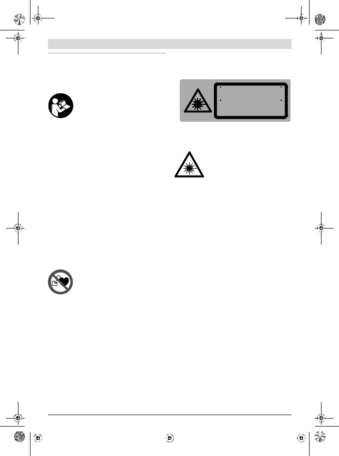
Keep the laser target plate 37 and the ceiling measurement plate 38 away from cardiac pacemakers. The magnets on the laser target plate and on the ceiling measurement plate generate a field that can impair the function of cardiac pacemakers.
Keep the laser target plate 37 and the ceiling measurement plate 38 away from magnetic data medium and magnetically-sensitive equipment. The effect of the magnets on the laser target plate and on the ceiling measurement plate can lead to irreversible data loss.
GRL 240 HV/GRL 250 HV
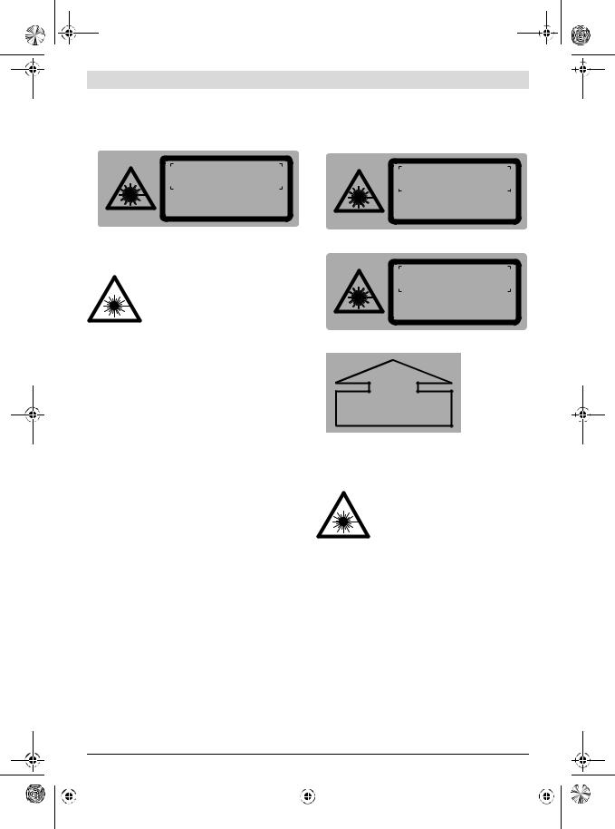
The measuring tool is provided with a warning label (marked with number 17 in the representation of the measuring tool on the graphics page).
Laser Radiation Class 2
do not stare into beam
IEC 60825-1:2014 <1mW, 635 nm
If the text of the warning label is not in your national language, stick the provided warning label in your national language over it before operating for the first time.
Do not direct the laser beam at persons or animals and do not stare into the direct or reflected laser beam yourself, not even from a distance. You could blind somebody, cause accidents or damage your eyes.
If laser radiation strikes your eye, you must deliberately close your eyes and immediately turn your head away from the beam.
Do not make any modifications to the laser equipment.
Do not allow children to use the laser measuring tool without supervision. They could unintentionally blind other persons or themselves.
|
1 609 92A 28U | (1.2.17) |
|
|
Bosch Power Tools |
|||
|
|
|
|
|
|
|
|
|
|
|
|
|
|
|
|
|
|
|
|
|
|
|
|
OBJ_BUCH-1492-005.book Page 9 Wednesday, February 1, 2017 7:09 AM
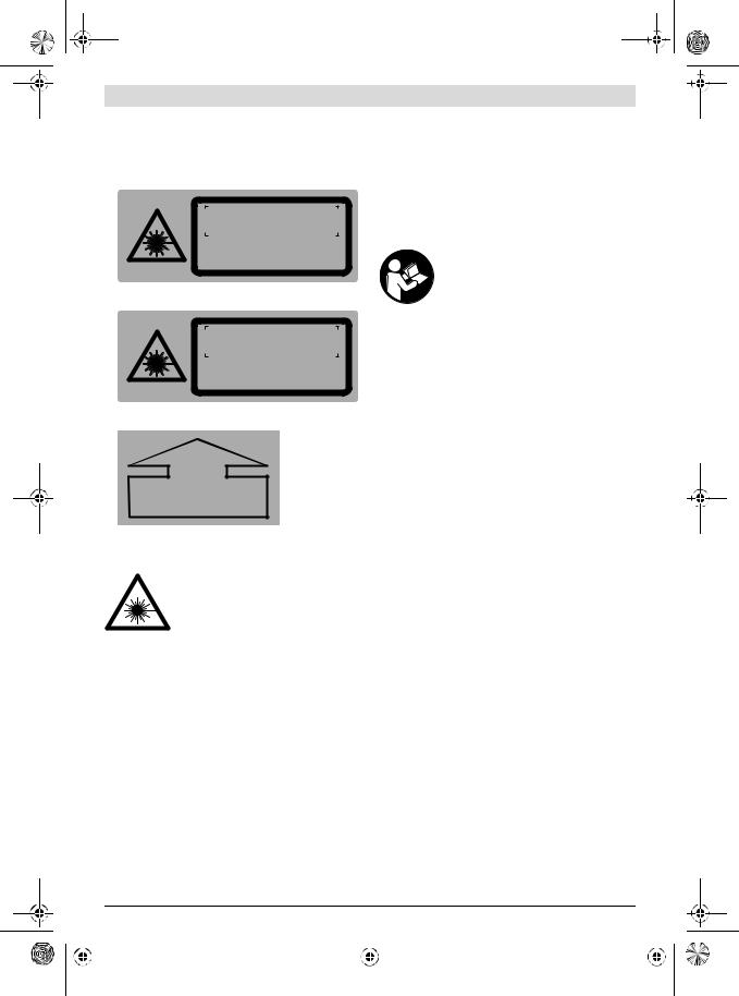
GRL 300 HV/GRL 300 HVG
The measuring tool is provided with two warning labels (marked with numbers 17 and 18 in the representation of the measuring tool on the graphics page).
GRL 300 HV:
LASER RADIATION Avoid direct eye exposure Class 3R laser product
IEC 60825-1:2014 <5 mW, 635 nm
GRL 300 HVG:
LASER RADIATION Avoid direct eye exposure Class 3R laser product
IEC 60825-1:2014 <5 mW, 532 nm
GRL 300 HV/GRL 300 HVG:
LASER
APERTURE
If the text of the warning labels is not in your national language, stick the provided warning labels in your national language over it before operating for the first time.
Do not direct the laser beam at persons or animals and do not look into the laser beam yourself. This measuring tool generates laser radiation from class 3R according to IEC 60825-1. Looking directly into the laser beam – even from a greater
distance – can cause damages to the eyes.
Avoid reflection of the laser beam on smooth surfaces such as windows or mirrors. A reflected laser beam can also cause damage to the eye.
The measuring tool should be operated only by persons that are familiar with the handling of laser devices.
According to EN 60825-1, this includes, among other things, the knowledge about the biological effects of the laser to the eyes and the skin as well as the correct usage of laser protection devices in order to avoid dangers.
Always set up the measuring tool in such a manner that the laser beams run far above or below eye level. This ensures that damage to the eyes will not occur.
Mark the area in which the measuring tool is being used with suitable laser warning labels. This prevents persons not involved from accessing the danger area.
Do not store the measuring tool at locations to which unauthorised persons have access. Persons not familiar
English | 9
with the operation of the measuring tool can cause harm to themselves and to others.
When using a class 3R measuring tool, observe possible national regulations. Non-observance of these regulations can lead to injury.
Make sure that the area of laser radiation is monitored or shielded. The limitation of laser radiation to controlled areas prevents eye damage to persons not involved.
Remote Control
Read and observe all instructions. The integrated protections in the measuring tool may be compromised if the measuring tool is not used in accordance with the instructions provided. SAVE THESE INSTRUCTIONS FOR FUTURE REFERENCE.
Have the remote control repaired only through a qualified repair person and only using identical replacement parts. This will ensure that the functionality of the remote control is maintained.
Do not operate the remote control in explosive atmospheres, such as in the presence of flammable liquids, gases or dusts. Sparks can be created in the remote control which may ignite the dust or fumes.
Product Description and
Specifications
Intended Use
Rotational Laser Level
The measuring tool is intended for determining and checking precise horizontal partitions, vertical lines, building lines and plumb points.
The measuring tool is suitable for indoor and outdoor use.
Remote Control
The remote control is intended for controlling rotational laser levels in indoor and outdoor use.
Product Features
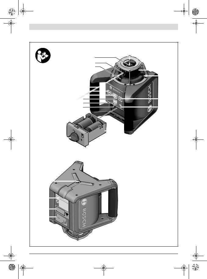
The numbering of the product features refers to the illustration of the rotational laser level and remote control on the graphics page.
Rotational Laser Level
1 Shock-warning indicator
2 Shock-warning button
3 Automatic levelling indicator
4 On/Off button of the rotational laser level
5Button for rotational operation and selection of the rotation speed
6 Variable laser beam
7 Reception lens for remote control
8 Exit opening for laser beam
9 Plumb beam
10Rotation head
11Button for line operation and line length selection
|
Bosch Power Tools |
|
|
1 609 92A 28U | (1.2.17) |
|||
|
|
|
|
|
|
|
|
|
|
|
|
|
|
|
|
|
|
|
|
|
|
|
|

OBJ_BUCH-1492-005.book Page 10 Wednesday, February 1, 2017 7:09 AM
10 | English
12Charge-control indicator
13Battery compartment
14Locking knob of the battery compartment
15Tripod mount 5/8"
16Serial number of the rotational laser level
17Laser warning label
18Warning label, laser radiation exit opening (GRL 300 HV/GRL 300 HVG)
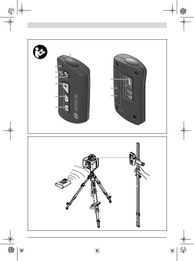
Remote control *
19Button on the remote control for rotation operation and selection of rotational speed
20Button on the remote control for line operation and selection of line length
21Shock-warning reset button
22Button for “rotation in clockwise direction”
23Button for “rotation in anticlockwise direction”
24Operation indicator
25Outlet opening for infra-red beam
26Serial number
27Latch of battery lid
28Battery lid
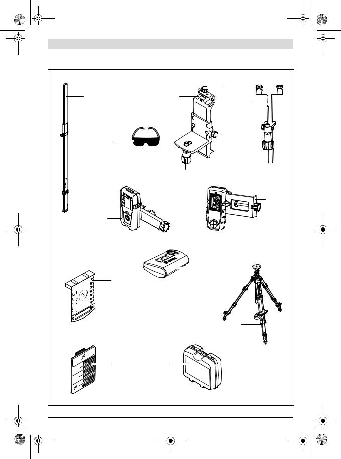
Accessories/Spare parts
29Laser receiver *
30Construction laser measuring rod*
31Tripod*
32Laser viewing glasses *
33Wall mount/alignment unit*
34Fastening screw of the wall mount *
35Screw of the alignment unit *
365/8" screw on wall mount*
37Laser target plate *
38Ceiling measurement plate*
39Case
* The accessories illustrated or described are not included as standard delivery.
Technical Data
Rotational Laser Level |
GRL 240 HV |
GRL 250 HV |
GRL 300 HV |
GRL 300 HVG |
Article number |
3 601 K61 C.. |
3 601 K61 6.. |
3 601 K61 5.. |
3 601 K61 7.. |
Working range (radius) 1) |
|
|
|
|
– without laser receiver, |
30 m |
30 m |
30 m |
50 m |
approx. |
||||
– with laser receiver, approx. |
125 m |
125 m |
150 m |
150 m |
Levelling Accuracy 1) 2) |
± 0.2 mm/m |
± 0.1 mm/m |
± 0.1 mm/m |
± 0.1 mm/m |
Self-levelling range, typically |
± 8 % (± 5 °) |
± 8 % (± 5 °) |
± 8 % (± 5 °) |
± 8 % (± 5 °) |
Levelling duration, typically |
15 s |
15 s |
15 s |
15 s |
Rotational speed |
150/300/600 min-1 |
150/300/600 min-1 |
150/300/600 min-1 |
150/300/600 min-1 |
Aperture angle for line |
10/25/50 ° |
10/25/50 ° |
10/25/50 ° |
10/25/50 ° |
operation |
||||
Operating temperature |
0 ... + 50 ° C |
– 10 ... + 50 ° C |
– 10 ... + 50 ° C |
0 ... + 40 ° C |
Storage temperature |
– 20 ... + 70 ° C |
– 20 ... + 70 ° C |
– 20 ... + 70 ° C |
– 20 ... + 70 ° C |
Relative air humidity, max. |
90 % |
90 % |
90 % |
90 % |
Laser class |
2 |
2 |
3R |
3R |
Laser type |
635 nm, < 1 mW |
635 nm, < 1 mW |
635 nm, < 5 mW |
532 nm, < 5 mW |
Laser beam Ø at the exit |
|
|
|
|
opening, approx. 1) |
4 mm |
4 mm |
4 mm |
4 mm |
Divergence |
0.4 mrad (full angle) |
0.4 mrad (full angle) |
0.4 mrad (full angle) |
0.4 mrad (full angle) |
– Laser point |
||||
Tripod mount (horizontal) |
5/8"-11 |
5/8"-11 |
5/8"-11 |
5/8"-11 |
Batteries (alkali-manganese) |
2 x 1.5 V LR20 (D) |
2 x 1.5 V LR20 (D) |
2 x 1.5 V LR20 (D) |
2 x 1.5 V LR20 (D) |
Operating time, approx. |
50 h |
50 h |
50 h |
30 h |
Weight according to |
1.8 kg |
1.8 kg |
1.8 kg |
1.8 kg |
EPTA-Procedure 01:2014 |
||||
Dimensions |
190 x 180 x 170 mm |
190 x 180 x 170 mm |
190 x 180 x 170 mm |
190 x 180 x 170 mm |
(length x width x height) |
||||
Degree of protection |
IP 54 (dust and splash |
IP 54 (dust and splash |
IP 54 (dust and splash |
IP 54 (dust and splash |
|
water protected) |
water protected) |
water protected) |
water protected) |
1)at 25 ° C
2)alongside the axes
For clear identification of your rotational laser level, see the serial number 16 on the type plate.
|
1 609 92A 28U | (1.2.17) |
|
|
Bosch Power Tools |
|||
|
|
|
|
|
|
|
|
|
|
|
|
|
|
|
|
|
|
|
|
|
|
|
|
OBJ_BUCH-1492-005.book Page 11 Wednesday, February 1, 2017 7:09 AM
Remote Control |
RC 1 |
Article number |
3 601 K69 9.. |
Working range3) |
30 m |
Operating temperature |
– 10 ° C ... + 50 ° C |
Storage temperature |
– 20 ° C ... + 70 ° C |
Battery |
1 x 1.5 V LR06 (AA) |
Weight according to |
|
EPTA-Procedure 01:2014 |
0.07 kg |
3) The working range can be decreased by unfavourable environmental conditions (e. g. direct sun irradiation).
For clear identification of your remote control, see the serial number 26 on the type plate.
Assembly
Power Supply of the Rotational Laser Level
Alkali-manganese batteries are recommended for the measuring tool.
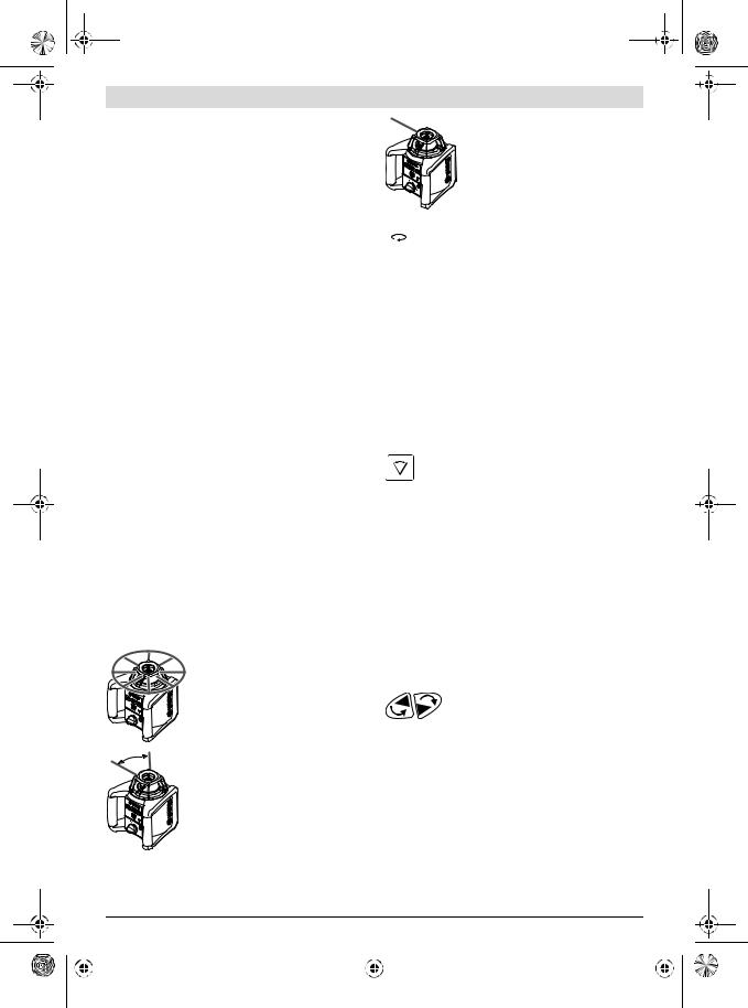
To open the battery compartment 13, turn the locking knob 14 to position  and pull out the battery compartment.
When inserting batteries, pay attention to the correct polarity according to the representation on the inside of the battery compartment.
Always replace all batteries at the same time. Only use batteries from one brand and with the identical capacity.
Shut the battery compartment 13 and turn the locking knob 14 to the  position.
In case the batteries have been inserted incorrectly, the measuring tool cannot be switched on. Insert the batteries with correct polarity.
Remove the batteries from the measuring tool when not using it for extended periods. When storing for extended periods, the batteries can corrode and selfdischarge.
Charge-control Indicator
When the charge-control indicator 12 flashes red for the first time, the measuring tool can still be operated for approx. 2 h.
When the charge-control indicator 12 lights up red continuously, measurements are no longer possible. The measuring tool switches off automatically after 1 minute.
Power Supply of the Remote Control
Using alkali-manganese batteries is recommended for operation of the remote control.
To open the battery lid 28, press the latch 27 in the direction of the arrow and remove the battery lid. Insert the battery provided. When inserting, pay attention to the correct polarity according to the representation on the inside of the battery compartment.
Remove the battery from the remote control when not using it for longer periods. When storing for longer periods, the battery can corrode and discharge itself.
English | 11
Operation
Starting Operation of the Rotational Laser Level
Protect the measuring tool against moisture and direct sun light.
Do not subject the measuring tool to extreme temperatures or variations in temperature. As an example, do not leave it in vehicles for a long time. In case of large variations in temperature, allow the measuring tool to adjust to the ambient temperature before putting it into operation. In case of extreme temperatures or variations in temperature, the accuracy of the measuring tool can be impaired.
Avoid heavy impact to or dropping down of the measuring tool. After severe exterior effects to the measuring tool, it is recommended to carry out an accuracy check (see “Levelling Accuracy of the Rotational Laser Level”, page 13) each time before continuing to work.
Switch the measuring tool off before transporting it.
This will save energy and prevent laser beams from being emitted accidentally.
Setting Up the Measuring Tool
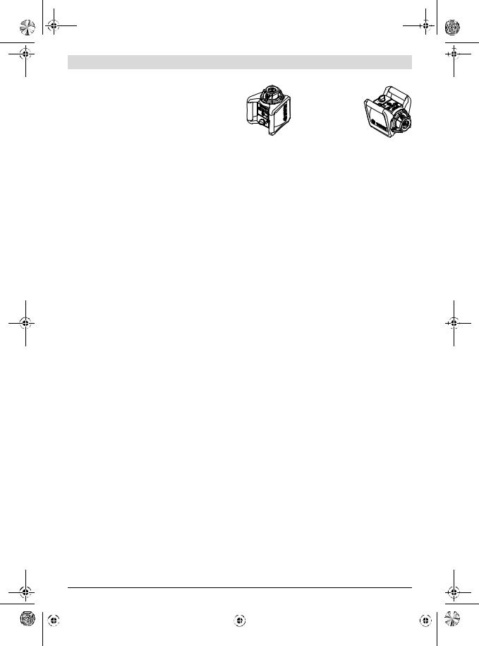
Horizontal position
Vertical position
Set up the measuring tool on a sturdy surface in the horizontal or vertical position; mount it on a tripod 31 or to the wall mount with alignment unit 33.
Due to the high levelling accuracy, the measuring tool reacts sensitively to ground vibrations and position changes. Therefore, pay attention that the position of the measuring tool is stable in order to avoid operational interruptions due to relevelling.
Switching On and Off
Do not direct the laser beam at persons or animals (especially not at their eye level), and do not stare into the laser beam yourself (not even from a distance). Immediately after switching on, the measuring tool sends out the vertical plumb beam 9 and the variable laser beam 6.
For switching on the measuring tool, press the On/Off button 4. The indicators 1, 3 and 12 light up briefly. The measuring tool immediately starts the automatic levelling. During the levelling, the levelling indicator 3 lights up green and the laser flashes in point operation.
The measuring tool is levelled in as soon as levelling indicator 3 lights up green continuously and the laser beam is steady. After the levelling is completed, the measuring tool automatically starts in rotational operation.
With the operating mode buttons 5 and 11, the operating modes can already be specified during levelling in (see “Operating Modes of the Rotational Laser Level”, page 12). In this case, the measuring tool starts in the set operating mode upon completion of levelling in.
|
Bosch Power Tools |
|
|
1 609 92A 28U | (1.2.17) |
|||
|
|
|
|
|
|
|
|
|
|
|
|
|
|
|
|
|
|
|
|
|
|
|
|
OBJ_BUCH-1492-005.book Page 12 Wednesday, February 1, 2017 7:09 AM
12 | English
To switch off the measuring tool, press the On/Off button 4 again.
Do not leave the switched-on measuring tool unattended and switch the measuring tool off after use. Other persons could be blinded by the laser beam.
To save the batteries, the measuring tool is automatically switched off when not within the self-levelling range for more than 2 h or when the shock warning is actuated for more than 2 h (see “Automatic Levelling of the Rotational Laser Level”, page 13). Reposition the measuring tool and switch it on again.
Starting Operation of the Remote Control
Protect the remote control against moisture and direct sunlight.
Do not subject the remote control to extreme temperatures or variations in temperature. As an example, do not leave it in vehicles for longer periods. In case of large variations in temperature, allow the remote control to adjust to the ambient temperature before putting it into operation.
The remote control remains ready for operation as long as a battery with sufficient voltage is inserted.
Set up the measuring tool in such a manner that the signals of the remote control can directly reach one of the reception lenses 7. When the remote control cannot be pointed directly against a reception lens, the working range is reduced. By reflecting the signal (e. g. against walls), the working range can be improved, even for indirect signals.
After pressing a button on the remote control, the illuminated operation indicator 24 indicates that a signal was sent out.
Switching the measuring tool on/off with the remote control is not possible.
Operating Modes of the Rotational Laser Level
Overview
All three operating modes are possible with the measuring tool in horizontal and vertical position.
Rotational Operation
Rotational operation is especially recommended when using the laser receiver. You can select between different rotational speeds.
Line Operation
In this operation mode, the variable laser beam moves within a limited aperture angle. This increases the visibility of the laser beam in comparison to rotational operation. You can select between different aperture angles.
Point Operation
This operation mode enables the best visibility of the variable laser beam. As an example, it is used for easy projecting of heights or checking building lines.
 Rotational Operation (150/300/600 min-1)
Each time after switching on, the measuring tool is in rotational operation mode with average rotational speed.
To switch from line operation to rotational operation, press the rotational operation button 5 or button 19 on the remote control. Rotational operation starts with average rotational speed.
To change the rotational speed, press the rotational operation button 5 or button 19 again until the requested speed is reached.
When working with the laser receiver, the highest rotational speed should be set. When working without laser receiver, reduce the rotational speed for improved visibility of the laser beam and use the laser viewing glasses 32.
Line Operation, Point Operation (10 °/25 °/50°, 0 °)
To switch to line or point operation, press the line operation button 11 or button 20 on the remote control. The measuring tool switches to line operation with the smallest aperture angle.
To change the aperture angle, press the line operation button 11 or button 20 on the remote control. The aperture angle is increased in two steps; at the same time, the rotational speed is increased with each step. When pressing the line operation button a third time, the measuring tool switches to point operation after brief post-pulsation. Pressing the line operation button again takes you back to line operation with the smallest aperture angle.
Note: Due to inertia, it is possible for the laser to slightly move beyond the end point of the laser line.
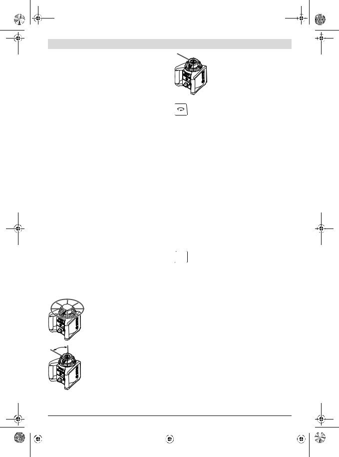
Rotating the Laser Line/Laser Dot or the
Rotational Plane (see figure A)
When the measuring tool is in the horizontal position, the laser line (in line operation) or the laser dot (in point operation) can be positioned within the rotational plane of the laser.
Rotation is possible by 360 °.
For this, manually turn the rotation head 10 to the desired position or use the remote control: Press button 22 to rotate in clockwise direction, and button 23 on the remote control to rotate in anticlockwise direction. In rotational operation, pressing the buttons has no effect.
|
1 609 92A 28U | (1.2.17) |
|
|
Bosch Power Tools |
|||
|
|
|
|
|
|
|
|
|
|
|
|
|
|
|
|
|
|
|
|
|
|
|
|
OBJ_BUCH-1492-005.book Page 13 Wednesday, February 1, 2017 7:09 AM
When the measuring tool is in the vertical position, it is possible to rotate the laser point, laser line or rotational plane around the vertical axis. Rotating is possible only within the self-levelling range (5 ° leftwards or rightwards) and only with the remote control.
Press button 22 on the remote control to rotate in clockwise direction, and button 23 on the remote control to rotate in anticlockwise direction.
Automatic Levelling of the Rotational Laser Level
Overview
After switching on, the measuring tool automatically detects the horizontal or vertical position. To change between the horizontal and vertical position, switch the measuring tool off, reposition it and switch on again.
After switching on, the measuring tool checks the horizontal and vertical position and automatically levels out any unevenness within the self-levelling range of approx. 8 % (5 °).
When the measuring tool is inclined by more than 8 % after switching on or after a position change, levelling in is no longer possible. In this case, the rotor is stopped, the laser flashes and levelling indicator 3 continuously lights up red. Reposition the measuring tool and wait for it to re-level. Without repositioning, the laser is automatically switched off after
2 minutes and the measuring tool after 2 hours.
When the measuring tool is levelled in, it continuously checks the horizontal and vertical position. Automatic re-levelling takes place after position changes. To avoid faulty measurements, the rotor stops during the levelling process, the laser flashes and the levelling indicator 3 flashes green.
 Shock-warning Function
The measuring tool has a shock-warning function; after position changes or shock to the measuring tool, or in case of ground vibrations, it keeps the measuring tool from levelling in at changed heights, and thus prevents vertical errors.
To switch on the shock-warning function, press the shockwarning button 2. The shock-warning indicator 1 continuously lights up green, and the shock-warning function is activated after 30 seconds.
When the levelling-accuracy range is exceeded after a position change of the measuring tool or when heavy ground vibrations are detected, the shock-warning function is actuated: The rotation is stopped, the laser flashes, the levelling indicator 3 goes out and the shock-warning indicator 1 flashes red. The current operating mode is stored.
After the shock warning has actuated, press the shockwarning button 2 on the measuring tool or the shock-warning reset button 21 on the remote control. The shock-warning function is restarted and the measuring tool starts the levelling. As soon as the measuring tool is levelled in (levelling indicator 3 continuously lights up green), it starts in the stored operating mode. Now, check the height of the laser beam with a reference point and correct the height, if required.
English | 13
When, after the shock-warning function has actuated, the function is not restarted by pressing button 2 on the measuring tool or the shock-warning reset button 21 on the remote control, the laser is automatically switched off after 2 minutes and the measuring tool after 2 hours.
To switch off the shock-warning function, press shockwarning button 2 once, or, when the shock warning is actuated (shock-warning indicator 1 flashing red) press it twice. When the shock-warning function is shut off, the shockwarning indicator 1 goes out.
The shock-warning function cannot be switched on or off with the remote control; it can only be restarted after having actuated.
Levelling Accuracy of the Rotational Laser Level
Influences on Accuracy
The ambient temperature has the greatest influence. Especially temperature differences occurring from the ground upward can divert the laser beam.
The deviations play a role in excess of approx. 20 m measuring distance and can easily reach two to four times the deviation at 100 m.
Because the largest difference in temperature layers is close to the ground, the measuring tool should always be mounted on a tripod when measuring distances exceeding 20 m. If possible, also set up the measuring tool in the centre of the work area.
Accuracy Check of the Measuring Tool
In addition to external influences, device-specific influences (e.g. falls or heavy impacts) can also lead to deviations. For this reason, check the calibration each time before beginning work.
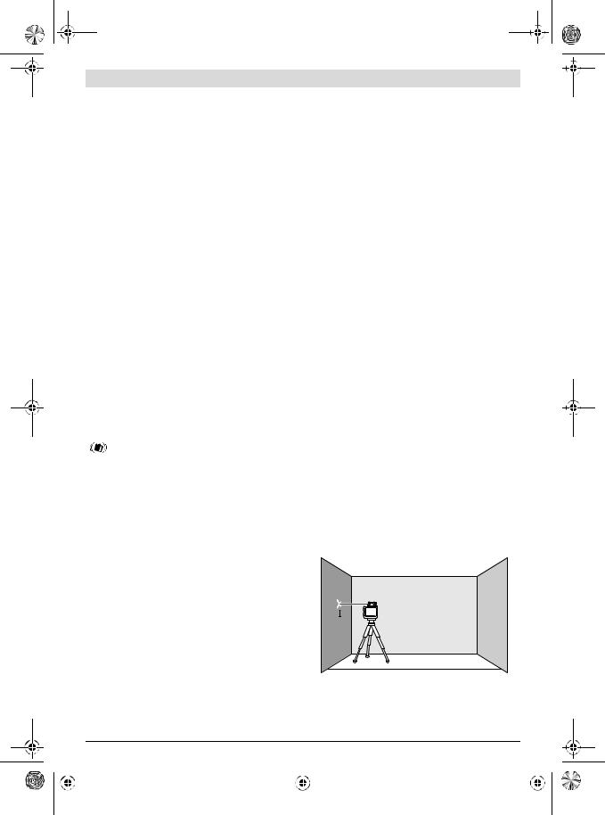
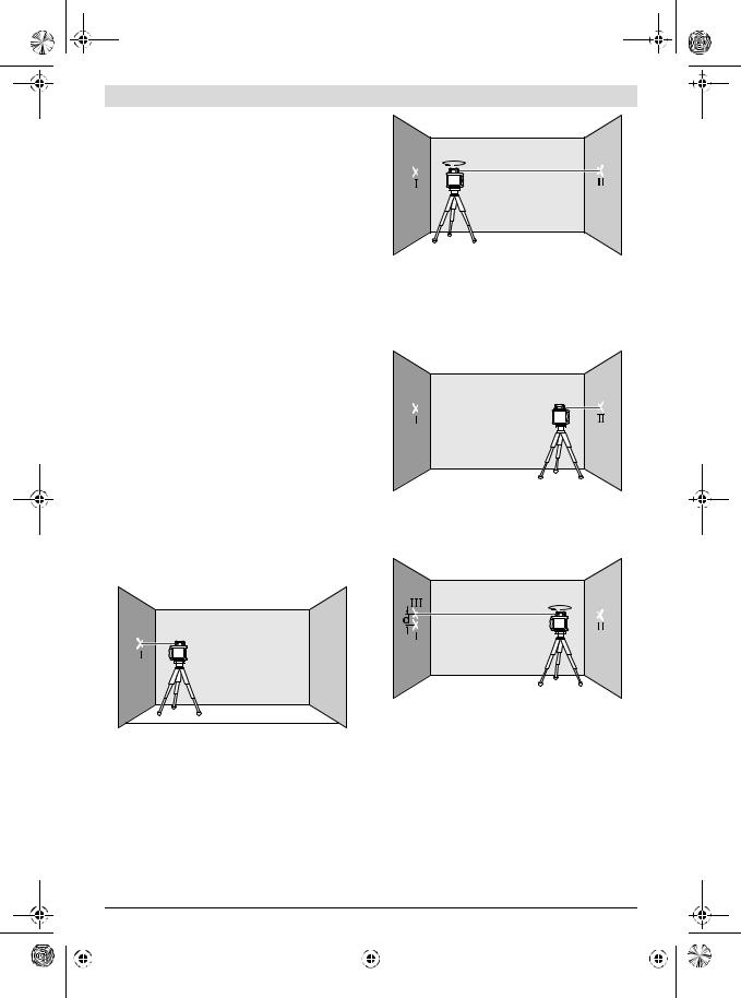
For the accuracy check, an unobstructed measuring distance of 20 m on firm ground between two walls A and B is required. With the measuring tool in the horizontal position, a transit measurement is to be carried out across both axes X and Y (both positive and negative) (altogether 4 complete measurements).
–Mount the measuring tool in the horizontal position onto a tripod 31 (accessory) or place it on a firm and level surface near wall A. Switch the measuring tool on.
A |
B |
20 m
–After levelling, direct the laser beam in point operation onto the close wall A. Mark the centre point of the laser beam on the wall (point I).
|
Bosch Power Tools |
|
|
1 609 92A 28U | (1.2.17) |
|||
|
|
|
|
|
|
|
|
|
|
|
|
|
|
|
|
|
|
|
|
|
|
|
|

OBJ_BUCH-1492-005.book Page 14 Wednesday, February 1, 2017 7:09 AM
14 | English
A |
B |
180°
–Turn the measuring tool around by 180 °, allow it to level in and mark the centre point of the laser beam on the opposite wall B (point II).
–Without turning the measuring tool, position it close to wall B. Switch the measuring tool on and allow it to level in.
A |
B |
–Align the height of the measuring tool (using the tripod or by underlaying, if required) in such a manner that the centre point of the laser beam is projected exactly against the previously marked point II on wall B.
A |
B |
180°
–Rotate the measuring tool by 180 ° without changing the height. Allow it to level in and mark the centre point of the laser beam on wall A (point III). Take care that point III is as vertical as possible above or below point I.
The difference d of both marked points I and III on wall A amounts to the actual deviation of the measuring tool for the measured axis.
Repeat the measuring procedure for the other three axes. For this, turn the measuring tool prior to each measuring procedure by 90 °.
–GRL 240 HV:
The maximum permitted deviation over the measuring section of 2 x 20 m = 40 m is as follows:
40 m x ± 0.2 mm/m = ± 8 mm.
The difference d between points I and III must therefore be maximum 16 mm in each of the four measuring procedures.
–GRL 250 HV/GRL 300 HV/GRL 300 HVG:
The maximum permitted deviation over the measuring section of 2 x 20 m = 40 m is as follows:
40 m x ± 0.1 mm/m = ± 4 mm.
The difference d between points I and III must therefore be maximum 8 mm in each of the four measuring procedures.
If the measuring tool should exceed the maximum deviation in any one of the four measuring procedures, have it checked at a Bosch after-sales service agent.
Working Advice
Always use the centre of the laser point for marking.
The size of the laser point changes with the distance.
Laser Viewing Glasses (Accessory)
The laser viewing glasses filter out ambient light. This enhances the laser visibility for the eye.
Do not use the laser viewing glasses as safety goggles.
The laser viewing glasses are used for improved visualisation of the laser beam, but they do not protect against laser radiation.
Do not use the laser viewing glasses as sun glasses or in traffic. The laser viewing glasses do not afford complete UV protection and reduce colour perception.
Working with the Laser Receiver (Accessory)
Under unfavourable light conditions (bright environment, direct sunlight) and for larger distances, use the laser receiver for improved finding of the laser beam 29.
When working with the laser receiver, select rotational operation with the highest rotational speed.
Before working with the laser receiver, read and observe the laser receiver operating instructions.
Working with the Remote Control (Accessory)
While pressing the operator buttons, the measuring tool can be brought out of alignment so that the rotation is briefly stopped. This effect is avoided when using the remote control.
Reception lenses 7 for the remote control are located on three sides of the measuring tool, among other locations above the control panel on the front side.
Working with the Tripod (Accessory)
The measuring tool is equipped with a 5/8" tripod mount for horizontal operation on a tripod. Place the measuring tool via the tripod mount 15 onto the 5/8" male thread of the tripod and screw the locking screw of the tripod tight.
On a tripod 31 with a measuring scale on the elevator column, the height difference can be adjusted directly.
|
1 609 92A 28U | (1.2.17) |
|
|
Bosch Power Tools |
|||
|
|
|
|
|
|
|
|
|
|
|
|
|
|
|
|
|
|
|
|
|
|
|
|

OBJ_BUCH-1492-005.book Page 15 Wednesday, February 1, 2017 7:09 AM
Working with Wall Mount/Alignment Unit (Accessory) (see figure B)
You can also mount the measuring tool to the wall mount with alignment unit 33. For this, screw the 5/8" screw 36 of the wall mount into the tripod mount 15 of the measuring tool.
Mounting to a wall: Mounting to a wall is recommended, e. g., for work above the elevation height of tripods or for work on unstable surfaces and without tripod. For this, fasten the wall mount 33, with the measuring tool mounted, as vertical as possible to a wall.
For mounting to the wall, you can either fasten the wall mount 33 with fastening screw 34 to a lath (width maximal 8 mm) or hang it up with two hooks.
Mounting on a tripod: The wall mount 33 can also be screwed onto a tripod with the tripod mount on the back side. This method of fastening is especially recommended for work where the rotational plane is to be aligned with a reference line.
With the alignment unit, the mounted measuring tool can be moved vertically (when mounted to the wall) or horizontally (when mounted to a tripod) within a range of approx. 16 cm. For this, loosen screw 35 on the alignment unit, move the measuring tool to the desired position, and retighten screw 35 again.
Working with the Ceiling Measurement Plate (see figure B)
As an example, the ceiling measurement plate 38 can be used for easy height adjustment of drop ceilings. Fasten the ceiling measurement plate with the magnetic holder, e. g., to a beam.
The reflecting half of the ceiling measurement plate improves the visibility of the laser beam in unfavourable conditions; the laser beam can also be seen from the rear side through the transparent half.
Working with the Laser Target Plate (Accessory) (see figure C)
With the laser target plate 37, the laser mark can be projected on the ground/floor or against a wall. With the magnetic holder, the laser target plate can also be fastened to ceiling constructions.
With the zero field and the scale, the offset or drop to the required height can be measured and projected at another location. This eliminates the necessity of precisely adjusting the measuring tool to the height to be projected.
The laser target plate 37 has a reflecting coating which improves the visibility of the laser beam from a larger distance or in case of strong sun rays. The luminosity can be recognized only if you look to the laser target plate in parallel to the laser beam.
English | 15
Working with the Measuring Rod (Accessory) (see figure J)
For checking irregularities or projecting gradients, it is recommended to use the measuring rod 30 together with the laser receiver.
A relative millimetre scale ( ±50 cm) is marked on the top of the measuring rod 30. Its zero height can be preset at the bottom of the elevator column. This allows for direct reading of deviations from the specified height.
Work Examples
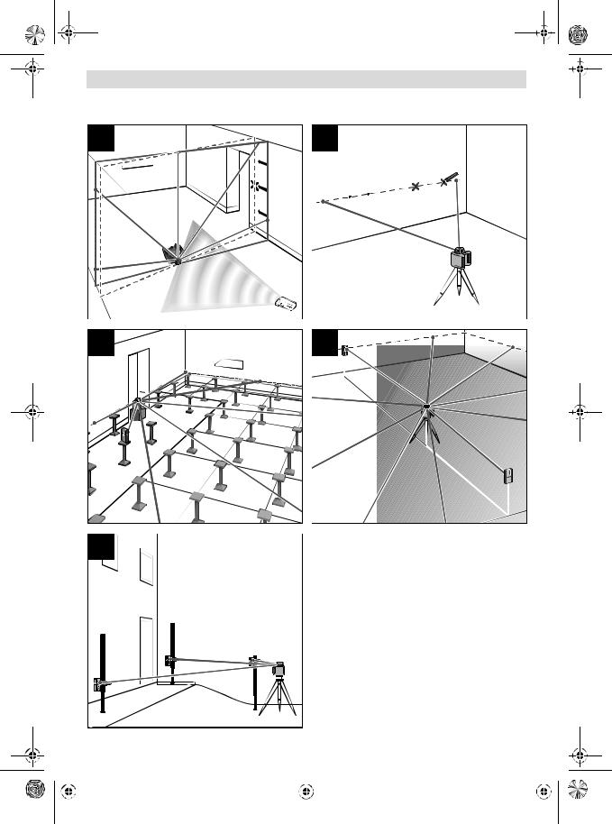
Projecting/Checking Heights (see figure C)
Position the measuring tool in the horizontal position onto a firm support or mount it onto a tripod 31 (accessory).
Working with tripod: Align the laser beam to the requested height. Project or check the height at the target location.
Working without tripod: Determine the height difference between the laser beam and the height at the reference point with the laser target plate 37. Project or check the measured height difference at the target location.
Parallel Alignment of a Plumb Beam/Projecting Right Angles (see figure D)
When right angles are to be projected or when partitions are to be aligned, the plumb beam 9 must be aligned parallel, meaning at the same distance to a reference line (e. g. a wall).
For this, set up the measuring tool in the vertical position and position it in such a manner that the plumb beam runs approximately parallel to the reference line.
For exact positioning, measure the clearance between plumb beam and reference line directly on the measuring tool with help of the laser target plate 37. Measure the clearance between plumb beam and reference line again as far away as possible from the measuring tool. Align the plumb beam in such a manner that it has the same clearance to the reference line as when measured directly at the measuring tool.
The right angle to the plumb beam 9 is indicated by the variable laser beam 6.
Indicating a Plumb Line/Vertical Plane (see figure E)
To indicate a plumb line or a vertical plane, set up the measuring tool in the vertical position. When the vertical plane is supposed to run at a right angle to a reference line (e. g. a wall), then align the plumb beam 9 with this reference line.
The plumb line is indicated by the variable laser beam 6.
|
Bosch Power Tools |
|
|
1 609 92A 28U | (1.2.17) |
|||
|
|
|
|
|
|
|
|
|
|
|
|
|
|
|
|
|
|
|
|
|
|
|
|
OBJ_BUCH-1492-005.book Page 16 Wednesday, February 1, 2017 7:09 AM
16 | English
Turning the Rotational Plane when in the Vertical Position (see figure F)
To align the vertical laser line or the rotational plane against a reference point on a wall, set up the measuring tool in the vertical position, and roughly align the laser line or the rotational plane with the reference point. For precise alignment with the reference point, press button 22 (clockwise rotation) or button 23 on the remote control (anticlockwise rotation).
Working without Laser Receiver (see figure G)
Under favourable light conditions (dark environment) and for short distances, it is possible to work without the laser receiver. For better visibility of the laser beam, either select line operation, or select point operation and manually rotate the rotation head 10 to the target location.
Working with the Laser Receiver (see figure H)
Under unfavourable light conditions (bright environment, direct sunlight) and for larger distances, use the laser receiver for improved finding of the laser beam. When working with the laser receiver, select rotational operation with the highest rotational speed.
Measuring Over Long Distances (see figure I)
When measuring over long distances, the laser receiver must be used to find the laser beam. In order to reduce interferences, the measuring tool should always be set up in the centre of the work surface and on a tripod.
Working Outdoors (see figure J)
The laser receiver should always be used when working outdoors.
When working on unstable ground, mount the measuring tool onto the tripod 31. Activate the shock-warning function in order to avoid faulty measurements in case of ground vibrations or shock to the measuring tool.
Overview of Indications
Laser beam |
Rotation of the laser* |
Switching on the measuring tool (1 s self-check)
green red green |
red |
|
|
|
|
Levelling in or re-levelling |
2x/s |
|
2x/s |
Measuring tool levelled in/ready for operation |
|
|
|
Self-levelling range exceeded |
2x/s |
|
|
Shock-warning function activated |
|
|
|
Shock warning actuated |
2x/s |
|
2x/s |
Battery voltage for ≤ 2 h operation |
|
|
2x/s |
Battery empty |
|
|
|
|
* for line and rotational operation |
||
|
2x/s |
Flashing frequency (twice per second) |
|
|
|
Continuous operation |
|
|
|
Function stopped |
|
Maintenance and Service
Maintenance and Cleaning
Keep the rotational laser level and remote control clean at all times.
Do not immerse the rotational laser level and remote control into water or other fluids.
Wipe off debris using a moist and soft cloth. Do not use any cleaning agents or solvents.
Particularly clean the surfaces at the outlet opening of the rotational laser level regularly and pay attention for any lint.
After-sales Service and Application Service
Our after-sales service responds to your questions concerning maintenance and repair of your product as well as spare parts. Exploded views and information on spare parts can also be found under:
www.bosch-pt.com
Bosch’s application service team will gladly answer questions concerning our products and their accessories.
In all correspondence and spare parts orders, please always include the 10-digit article number given on the nameplate of the product.
|
1 609 92A 28U | (1.2.17) |
|
|
Bosch Power Tools |
|||
|
|
|
|
|
|
|
|
|
|
|
|
|
|
|
|
|
|
|
|
|
|
|
|

OBJ_BUCH-1492-005.book Page 17 Wednesday, February 1, 2017 7:09 AM
People’s Republic of China China Mainland
Bosch Power Tools (China) Co., Ltd. 567, Bin Kang Road
Bin Jiang District 310052 Hangzhou, P. R. China
Service Hotline: 4008268484 Fax: (0571) 87774502
E-Mail: contact.ptcncn.bosch.com www.bosch-pt.com.cn
HK and Macau Special Administrative Regions
Robert Bosch Hong Kong Co. Ltd. 21st Floor, 625 King’s Road North Point, Hong Kong
Customer Service Hotline: +852 2101 0235 Fax: +852 2590 9762
E-Mail: infohk.bosch.com www.bosch-pt.com.hk
Indonesia
PT Robert Bosch Palma Tower 10th Floor
Jl. RA Kartini II-S Kaveling 6 Sek II Pondok Pinang, Kebayoran Lama Jakarta Selatan 12310 Indonesia
Tel.: (0 21) 30 05 5800
Fax: (0 21) 30 05 58 01
E-Mail: boschpowertoolsid.bosch.com www.bosch-pt.co.id
Philippines
Robert Bosch, Inc.
28th Floor Fort Legend Towers, 3rd Avenue corner 31st Street, Fort Bonifacio Global City, 1634 Taguig City, Philippines Tel.: (02) 8703871
Fax: (02) 8703870 matheus.contieroph.bosch.com www.bosch-pt.com.ph
Bosch Service Center: 9725-27 Kamagong Street San Antonio Village
Makati City, Philippines Tel.: (02) 8999091 Fax: (02) 8976432
E-Mail: rosalie.dagdaganph.bosch.com
Malaysia
Robert Bosch Sdn. Bhd. No. 8A, Jalan 13/6 G.P.O. Box 10818 46200 Petaling Jaya Selangor, Malaysia
Tel.: (03) 79663194
Fax: (03) 79583838
E-Mail: cheehoe.onmy.bosch.com Toll-Free: 1800 880188 www.bosch-pt.com.my
English | 17
Thailand
Robert Bosch Ltd.
Liberty Square Building
No. 287, 11 Floor
Silom Road, Bangrak
Bangkok 10500
Tel.: 02 6393111
Fax: 02 2384783
Robert Bosch Ltd., P. O. Box 2054
Bangkok 10501, Thailand
www.bosch.co.th
Bosch Service – Training Centre
La Salle Tower Ground Floor Unit No.2
10/11 La Salle Moo 16
Srinakharin Road
Bangkaew, Bang Plee
Samutprakarn 10540
Thailand
Tel.: 02 7587555
Fax: 02 7587525
Singapore
Powerwell Service Centre Ptd Ltd
65 Ubi Crescent, #06-03 Hola Centre Singapore 408559
Tel.: 6746 9770/71 Fax: 6746 9760
E-Mail: powerwellscgmail.com Toll-Free: 1800 3338333 www.bosch-pt.com.sg
Vietnam
Robert Bosch Vietnam Co. Ltd 13th Floor , 194 Golden Building 473 Dien Bien Phu Street
Ward 25, Binh Thanh District 84 Ho Chi Minh City
Vietnam
Tel.: (08) 6258 3690
Fax: (08) 6258 3692 Hotline: (08) 6250 8555
E-Mail: tuvankhachhang-ptvn.bosch.com www.bosch-pt.com.vn www.baohanhbosch-pt.com.vn
Australia, New Zealand and Pacific Islands
Robert Bosch Australia Pty. Ltd. Power Tools
Locked Bag 66
Clayton South VIC 3169
Customer Contact Center Inside Australia:
Phone: (01300) 307044 Fax: (01300) 307045 Inside New Zealand: Phone: (0800) 543353 Fax: (0800) 428570 Outside AU and NZ: Phone: +61 3 95415555 www.bosch-pt.com.au www.bosch-pt.co.nz
|
Bosch Power Tools |
|
|
1 609 92A 28U | (1.2.17) |
|||
|
|
|
|
|
|
|
|
|
|
|
|
|
|
|
|
|
|
|
|
|
|
|
|
OBJ_BUCH-1492-005.book Page 18 Wednesday, February 1, 2017 7:09 AM
18 |
Egypt
Unimar
20 Markaz kadmat
El tagmoa EL Aoul – New Cairo
Tel: +2 02 224 76091 - 95 / + 2 02 224 78072 - 73 Fax:+2 02 224 78075
E-Mail: adelzakiunimaregypt.com
Ethiopia
Forever plc
Kebele 2,754, BP 4806, Addis Ababa , Ethiopia
Tel: +251 111 560 600, +251 111 560 600 E-Mail: foreverplcethionet.et
Nigeria
C. Woermann Ltd. P.O. Box 318
6, Badejo Kalesanwo Street Matori Industrial Estate Lagos, Nigeria
Tel: +234 17 736 498, +234 17 730 904 E-Mail: d.kornemannwoermann-nigeria.com
Republic of South Africa
Customer service
Hotline: (011) 6519600
Gauteng – BSC Service Centre
35 Roper Street, New Centre Johannesburg
Tel.: (011) 4939375
Fax: (011) 4930126 E-Mail: bsctoolsicon.co.za
KZN – BSC Service Centre
Unit E, Almar Centre
143 Crompton Street Pinetown
Tel.: (031) 7012120
Fax: (031) 7012446
E-Mail: bsc.durza.bosch.com
Western Cape – BSC Service Centre
Democracy Way, Prosperity Park
Milnerton
Tel.: (021) 5512577
Fax: (021) 5513223
E-Mail: bsczsd.co.za
Bosch Headquarters
Midrand, Gauteng
Tel.: (011) 6519600
Fax: (011) 6519880
E-Mail: rbsa-hq.ptsza.bosch.com
Disposal
The rotational laser level, remote control, batteries, accessories and packaging should be sorted for environmentalfriendly recycling.
Do not dispose of the rotational laser level, remote control and batteries into household waste!
Subject to change without notice.

機器を使用したり、指定以外の方法でお取り扱い になったりすると、危険な電磁波を放出する恐れ があります。
助けるものであり、レーザー光から目を保護する ものではありません。
低下させます。
れによりメジャーリングツールの安全性が確実に 保護されます。
ら火花が発生し、粉塵や蒸気に引火する恐れがあ ります。
3738
37 38
|
1 609 92A 28U | (1.2.17) |
|
|
Bosch Power Tools |
|||
|
|
|
|
|
|
|
|
|
|
|
|
|
|
|
|
|
|
|
|
|
|
|
|
OBJ_BUCH-1492-005.book Page 19 Wednesday, February 1, 2017 7:09 AM
GRL 240 HV/GRL 250 HV
17
Laser Radiation Class 2
do not stare into beam
IEC 60825-1:2014 <1mW, 635 nm
眩しさを与えたり、事故を引き起こ したり、目に障害を与えるおそれが あります。
光が他者の目に入ると視力に影響を及ぼす場合が あります。
| 19
GRL 300 HV/GRL 300 HVG
2 17 18
GRL 300 HV:
LASER RADIATION Avoid direct eye exposure Class 3R laser product
IEC 60825-1:2014 <5 mW, 635 nm
GRL 300 HVG:
LASER RADIATION Avoid direct eye exposure Class 3R laser product
IEC 60825-1:2014 <5 mW, 532 nm
GRL 300 HV/GRL 300 HVG:
LASER
APERTURE
ルはレーザークラス3R
IEC 60825- 1––
に害をおよぼすこともあります。
い。EN 60825- 1
|
Bosch Power Tools |
|
|
1 609 92A 28U | (1.2.17) |
|||
|
|
|
|
|
|
|
|
|
|
|
|
|
|
|
|
|
|
|
|
|
|
|
|
OBJ_BUCH-1492-005.book Page 20 Wednesday, February 1, 2017 7:09 AM
20 |
傷を回避できます。
な状況を作らないようにしてください。
ることのないように保管してください。
3R
を持たない者を近づけないようにすることで無関 係者に対しての危険を防ぐことができます。
能性が確実に維持されます。
気に引火する恐れがあります。
1 2
3
4
6
7
8
9
155/8"
(GRL 300 HV/GRL 300 HVG)
*
/
29*
30*
31*
32*
33/ *
34*
|
1 609 92A 28U | (1.2.17) |
|
|
Bosch Power Tools |
|||
|
|
|
|
|
|
|
|
|
|
|
|
|
|
|
|
|
|
|
|
|
|
|
|
OBJ_BUCH-1492-005.book Page 21 Wednesday, February 1, 2017 7:09 AM
|
|
|
|
| 21 |
|
35 * |
|
38 * |
|
|
|
36 5/8" * |
39 |
|
|
||
37 * |
* |
||||
|
|
|
|
|
|
|
|
|
|
|
|
|
GRL 240 HV |
GRL 250 HV |
GRL 300 HV |
GRL 300 HVG |
|
|
3 601 K61 C.. |
3 601 K61 6.. |
3 601 K61 5.. |
3 601 K61 7.. |
|
|
|
|
|
|
|
1) |
|
|
|
|
|
– |
30 m |
30 m |
30 m |
50 m |
|
– |
125 m |
125 m |
150 m |
150 m |
|
|
|
|
|
|
|
1) 2) |
±0.2 mm/m |
±0.1 mm/m |
±0.1 mm/m |
±0.1 mm/m |
|
|
|
|
|
|
|
|
±8 % (±5°) |
±8 % (±5°) |
±8 % (±5°) |
±8 % (±5°) |
|
|
|
|
|
|
|
|
15 |
15 |
15 |
15 |
|
|
|
|
|
|
|
|
150/300/600 rpm |
150/300/600 rpm |
150/300/600 rpm |
150/300/600 rpm |
|
|
|
|
|
|
|
|
10/25/50° |
10/25/50° |
10/25/50° |
10/25/50° |
|
|
|
|
|
|
|
|
0...+50 °C |
–10...+50 °C |
–10...+50 °C |
0...+40 °C |
|
|
|
|
|
|
|
|
–20...+70 °C |
–20...+70 °C |
–20...+70 °C |
–20...+70 °C |
|
|
|
|
|
|
|
|
90 % |
90 % |
90 % |
90 % |
|
|
|
|
|
|
|
|
2 |
2 |
3R |
3R |
|
|
|
|
|
|
|
|
635 nm, <1 mW |
635 nm, <1 mW |
635 nm, <5 mW |
532 nm, <5 mW |
|
|
|
|
|
|
|
Ø |
|
|
|
|
|
1) |
4 mm |
4 mm |
4 mm |
4 mm |
|
|
|
|
|
|
|
– |
0.4 mrad |
0.4 mrad |
0.4 mrad |
0.4 mrad |
|
|
|
|
|
|
|
|
5/8"-11 |
5/8"-11 |
5/8"-11 |
5/8"-11 |
|
|
|
|
|
|
|
|
|
|
|
|
|
|
2 x 1.5 V LR20 (D) 2 x 1.5 V LR20 (D) 2 x 1.5 V LR20 (D) 2 x 1.5 V LR20 (D) |
||||
|
|
|
|
|
|
|
50 |
50 |
50 |
30 |
|
|
|
|
|
|
|
EPTA-Procedure |
|
|
|
|
|
01:2014 |
1.8 kg |
1.8 kg |
1.8 kg |
1.8 kg |
|
× × 190 x 180 x 170 mm |
190 x 180 x 170 mm |
190 x 180 x 170 mm |
190 x 180 x 170 mm |
|
|
|
|
|
|
|
IP 54 ( ) |
IP 54 ( ) |
IP 54 ( ) |
IP 54 ( ) |
1)25 °C
16
|
|
|
RC 1 |
|
3 |
601 K69 9.. |
|
|
|
|
|
3) |
|
|
30 m |
|
–10 °C...+50 |
°C |
|
|
|
|
|
|
–20 °C...+70 |
°C |
|
|
|
|
|
|
1 x 1.5 |
V LR06 (AA) |
|
|
|
|
|
EPTA-Procedure |
|
|
|
01:2014 |
|
0.07 kg |
|
3) 26
電池収納部13 14  13 14
13 14 
|
Bosch Power Tools |
|
|
1 609 92A 28U | (1.2.17) |
|||
|
|
|
|
|
|
|
|
|
|
|
|
|
|
|
|
|
|
|
|
|
|
|
|
OBJ_BUCH-1492-005.book Page 22 Wednesday, February 1, 2017 7:09 AM
22 |
|
|
|
|
|
|
|
|
|
|
|
|
|
|
|
|
|
|
|
|
|
|
|
|
|
31 |
|
33 |
||
12 |
||
|
||
2 |
||
|
||
12 |
||
|
||
1 |
||
|
||
|
||
|
||
|
|
on/off |
|
|
||
|
|
|
|
|
|
27 |
|
|
28 |
|
|
|
9 6 |
|
|
|
|
|
||
|
|
|
4 1 3 |
||
|
||
|
12 |
|
|
|
|
3 |
||
|
||
|
|
|
3 |
||
|
||
|
|
|
|
|
|
|
||
|
||
5 11 |
||
|
||
|
||
|
||
|
||
|
||
23 |
||
|
||
|
||
|
||
|
||
|
||
|
||
|
||
/ 4 |
||
|
||
|
は、作業を継続する前に必ず精度チェックをおこ
ベリング精度」、25
光が放出されるのを防ぎます。
|
1 609 92A 28U | (1.2.17) |
|
|
Bosch Power Tools |
|||
|
|
|
|
|
|
|
|
|
|
|
|
|
|
|
|
|
|
|
|
|
|
|
|
OBJ_BUCH-1492-005.book Page 23 Wednesday, February 1, 2017 7:09 AM
|
| 23 |
2 |
|
2 |
|
|
|
|
|
|
|
24 |
|
|
|
|
|
|
(150/300/600 rpm) |
|
|
|
|
に温度変化のある場所でリモコンを使用しないで
を周囲温度に順応させてからスイッチを入れてく ださい。
7
プ24
おこなえません。
3


す。
リングツールでは様々な開口角を 選択することができます。
る際には、ローテーションモード用ボタン519
ボタン5 19
ザー受光器を使用せずに作業をおこなう場合には、 ローター回転速度を低下させるかレーザーメガネ32
 (10°/25°/50°, 0°)
には、ラインモード用ボタン1120
11 202 3
の終点からやや外側にずれることがあります。
|
Bosch Power Tools |
|
|
1 609 92A 28U | (1.2.17) |
|||
|
|
|
|
|
|
|
|
|
|
|
|
|
|
|
|
|
|
|
|
|
|
|
|
OBJ_BUCH-1492-005.book Page 24 Wednesday, February 1, 2017 7:09 AM
24 |
|
|
|
/ |
|
|||||
|
|
|
|
|
|||||
|
|
|
A |
|
|||||
|
|
|
|
||||||
|
|
|
|
|
|
|
|||
|
|
|
|
||||||
|
|
3 |
|||||||
|
|
|
|||||||
|
|
|
|
||||||
|
|
|
|
|
|
|
|||
|
|
360° |
|
|
|
|
|
||
|
|
10 |
|
|
|
|
|
||
|
|
|
|
|
|||||
|
|
22 |
|
||||||
|
|
|
|||||||
|
|
23 |
|||||||
|
|
|
|||||||
|
|
|
|||||||
|
|
|
|||||||
|
|
|
|||||||
|
|
|
|||||||
|
|
|
|||||||
|
|
|
|||||||
|
|
|
|||||||
|
|
|
|||||||
|
|
|
|||||||
|
|
2 |
|||||||
|
|
|
|||||||
|
|
1 30 |
|||||||
|
|
5° |
|||||||
|
|
|
|||||||
|
|
|
|||||||
|
|
|
|||||||
|
|
|
|||||||
|
|
|
|||||||
|
|
22 |
|||||||
|
|
|
|||||||
|
|
23 |
|||||||
|
|
|
|||||||
|
|
|
|
|
|||||
|
|
|
3 1 |
||||||
|
|
|
|
||||||
|
|
|
|
|
|
|
|
||
|
|
|
|
||||||
|
|
8 |
2 |
||||||
|
|
5° |
21 |
||||||
|
|
|
2 2 |
||||||
|
|
|
|
||||||
|
|
8 |
|
||||||
|
|
|
2 1 |
||||||
|
|
|
1 |
||||||
|
|
3 |
2 |
||||||
|
|
|
1 |
||||||
|
|
|
|
||||||
|
|
|
|
||||||
|
|
2 |
|||||||
|
|
|
|||||||
|
|
2 |
|||||||
|
|
|
|
|
|
||||
|
|
|
|
||||||
|
|
|
|
|
2 |
||||
|
|
|
21 |
||||||
|
|
|
|
||||||
|
|
|
|
||||||
|
|
|
3 |
||||||
|
|
|
|
||||||
|
|
|
|
||||||
|
|
|
|
|
|
||||
|
|
|
|
|
|
|
|
|
|
|
|
1 609 92A 28U | (1.2.17) |
|
Bosch Power Tools |
|
|
|||
|
|
|
|
|
|
|
|
|
|
|
|
|
|
|
|
|
|
|
|
|
|
|
|
|
|
|
|
|
|
OBJ_BUCH-1492-005.book Page 25 Wednesday, February 1, 2017 7:09 AM
と異なると、レーザー光が適切に作用しなくなるこ とがあります。
20 m 100 m 20 m2 4
ていることから、測定距離が20 m
作業開始前に毎回精度チェックを行ってください。
A B20 mX YX Y 4
–A31
A |
B |
20 m
– ドットを壁面A ( I)
| 25
A |
B |
180°
–180° B( II)
–B
A |
B |
–II B
A |
B |
180°
–180°A( III) III I
A I IIId
3 90°
|
Bosch Power Tools |
|
|
1 609 92A 28U | (1.2.17) |
|||
|
|
|
|
|
|
|
|
|
|
|
|
|
|
|
|
|
|
|
|
|
|
|
|
OBJ_BUCH-1492-005.book Page 26 Wednesday, February 1, 2017 7:09 AM
26 |
–GRL 240 HV:
2 x 20 m = 40 m
40 m x ±0.2 mm/m = ±8 mm
I III d 416 mm
–GRL 250 HV/GRL 300 HV/GRL 300 HVG:
2 x 20 m = 40 m
40 m x ±0.1 mm/m = ±4 mm
I III d 48 mm
73
5/8" 155/8"
4 |
31 |
|
|
||
1 |
||
|
||
|
|
|
|
||
|
B |
|
|
変化します。
助けるものであり、レーザー光から目を保護する ものではありません。
低下させます。
する場合には、レーザー受光器29
335/8" 3615
33
3334 8 mm2
33
リングツールを約16 cm 3535
B
38
|
1 609 92A 28U | (1.2.17) |
|
|
Bosch Power Tools |
|||
|
|
|
|
|
|
|
|
|
|
|
|
|
|
|
|
|
|
|
|
|
|
|
|
 Loading...