


GRL160DHV
IMPORTANT: IMPORTANT : IMPORTANTE:
Read Before Using Lire avant usage Leer antes de usar
Operating/Safety Instructions
Consignes de fonctionnement/sécurité
Instrucciones de funcionamiento y seguridad
For English Version Version française Versión en español
See page 6 Voir page 22 Ver la página 38
1-877-BOSCH99 (1-877-267-2499) www.boschtools.com
Call Toll Free for
Consumer Information
& Service Locations
Pour obtenir des informations
et les adresses de nos centres
de service après-vente,
appelez ce numéro gratuit
Llame gratis para
obtener información
para el consumidor y
ubicaciones de servicio
GRL160DHV
-2-
4
3
2
1
5
6
6
11
12
7
8
10
9
-3-
13
14
15
19181716
21 20
-4-
22
26
34
27
33
26
27
34
33
38
39
28
3
29
31
22
23
29
31
24
30
28
43
42
30
23
35
44 45 46
3736
32
2524
32
41 40
16
17
25

47
48
49
50
51
-6-
Read all instructions. Failure to follow all instructions listed below may
result in hazardous radiation exposure, electric shock, fire and/or
serious injury. The term “tool” in all of the warnings listed below refers to your mains-operated
(corded) tool or battery-operated (cordless) tool.
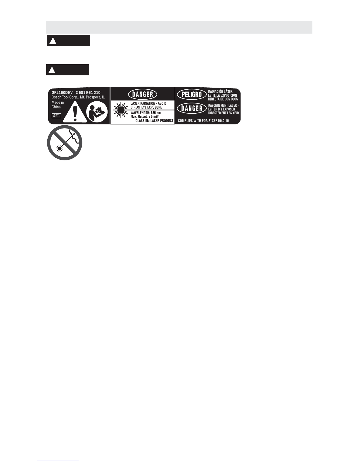
The following labels are on your laser tool for your convenience and
safety. They indicate where the laser light is emitted by the tool.
ALWAYS BE AWARE of their location when using the tool.
Do not direct the laser beam at persons or animals and do not stare into the
laser beam yourself. This tool produces laser class IIIa laser radiation. This can
lead to persons being blinded.
DO NOT remove or deface any warning or caution labels. Removing labels
increases the risk of exposure to laser radiation.
Use of controls or adjustments or performance of procedures other than those specified in this
manual, may result in hazardous radiation exposure.
ALWAYS make sure that any bystanders in the vicinity of use are made aware of the dangers
of looking directly into the laser tool.
DO NOT place the laser tool in a position that may cause anyone to stare into the laser beam
intentionally or unintentionally. Serious eye injury could result.
ALWAYS position the laser tool securely. Damage to the laser tool and/or serious injury to the
user could result if the laser tool fails.
ALWAYS use only the accessories that are recommended by the manufacturer of your laser
tool. Use of accessories that have been designed for use with other laser tools could result in
serious injury.
DO NOT use this laser tool for any purpose other than those outlined in this manual. This could
result in serious injury.
DO NOT leave the laser tool “ON” unattended in any operating mode.
DO NOT disassemble the laser tool. There are no user serviceable parts inside. Do not modify
the product in any way. Modifying the laser tool may result in hazardous laser
radiation exposure.
DO NOT use the laser viewing glasses as safety goggles. The laser viewing glasses are used
for improved visualization of the laser beam, but they do not protect against laser radiation.
DO NOT use the laser viewing glasses as sun glasses or in traffic. The laser viewing glasses
do not afford complete UV protection and reduce color perception.
DO NOT use any optical tools such as, but not limited to, telescopes or transits to view the
laser beam. Serious eye injury could result.
DO NOT stare directly at the laser beam or project the laser beam directly into the eyes of
others. Serious eye injury could result.
SAVE THESE INSTRUCTIONS
General Safety Rules
!
WARNING
!
WARNING

-7-
FCC Statement
This product has been tested and found to comply with the limits for a Class B digital device,
pursuant to Part 15 of the FCC rules. These limits are designed to provide reasonable
protection against harmful interference in a residential installation. This equipment generates,
uses, and can radiate radio frequency energy and, if not installed and used in accordance with
the instructions, may cause harmful interference to radio communications. However, there is
no guarantee that interference will not occur in a particular installation. If this equipment does
cause harmful interference to radio or television reception, which can be determined by turning
the equipment off and on, the user is encouraged to try to correct the interference by one or
more of the following measures:
• Reorient or relocate the receiving antenna.
• Increase the separation between the equipment and receiver.
• Consult the dealer or an experienced radio/TV technician for help.
SAVE THESE INSTRUCTIONS
Work area safety
Keep work area clean and well lit.
Cluttered or dark areas invite accidents.
DO NOT operate the laser tool around
children or allow children to operate the
laser tool. Serious eye injury could result.
Electrical safety
Batteries can explode or
leak, cause injury or fire.
To reduce this risk, always follow all
instructions and warnings on the battery label
and package.
DO NOT short any battery terminals.
DO NOT charge alkaline batteries.
DO NOT mix old and new batteries. Replace
all of them at the same time with new
batteries of the same brand and type.
DO NOT mix battery chemistries.
Dispose of or recycle batteries per
local code.
DO NOT dispose of batteries in fire.
Keep batteries out of reach of children.
Remove batteries if the device will not be
used for several months.
Personal safety
Stay alert, watch what you are doing and
use common sense when operating a
tool. Do not use a tool while you are tired
or under the influence of drugs, alcohol
or medication. A moment of inattention
while operating a tool may result in serious
personal injury or incorrect
measurement results.
Use safety equipment. Always wear eye
protection. Safety equipment such as dust
mask, non-skid safety shoes, hard hat, or
hearing protection used for appropriate
conditions will reduce personal injuries.
Use and care
Use the correct tool for your application.
The correct tool will do the job better
and safer.
Do not use the tool if the switch does not
turn it on and off. Any tool that cannot be
controlled with the switch is dangerous and
must be repaired.
Store idle tool out of the reach of children
and do not allow persons unfamiliar with
the tool or these instructions to operate
the tool. Tools are dangerous in the hands
of untrained users.
Maintain tools. Check for misalignment or
binding of moving parts, breakage of
parts and any other condition that may
affect the operation. If damaged, tool
repaired before use. Many accidents are
caused by poorly maintained tools.
Use the tool, accessories, etc., in
accordance with these instructions and in
the manner intended for the particular
type of tool, taking into account the
working conditions and the work to be
performed. Use of the tool for operations
different from those intended could result in a
hazardous situation.
Service
Have your tool serviced by a qualified
repair person using only identical
replacement parts. This will ensure that the
safety of the tool is maintained.
Develop a periodic maintenance schedule
for tool. When cleaning a tool be careful
not to disassemble any portion of the tool
since internal wires may be misplaced or
pinched or may be improperly mounted.
Certain cleaning agents such as gasoline,
carbon tetrachloride, ammonia, etc. may
damage plastic parts.
SAVE THESE INSTRUCTIONS.
!
WARNING
-8-
This tool projects rotating, dithering lasers and is intended for accurate transfer and alignment of
plumb, level, and 90-degree lines.
• Plumbing (Making vertical) — Use the Vertical Spin or Line Dither/Scan laser for indoor
and outdoor plumb and alignment applications, such as plumbing framing or
aligning conduit.
• Leveling — Use the Horizontal Spin or Line Dither/Scan laser for indoor and out door level
applications, such as leveling cabinetry, setting concrete forms, or leveling electrical outlets.
• Grading — Use the tool at a sloped angle for indoor and outdoor level applications, such
as grading driveways or swimming pools.
• Squaring— Use both lasers simultaneously to generate a crosshair for level and plumb
alignment applications, such as aligning cabinetry or tiling.
Intended Use
Preparation
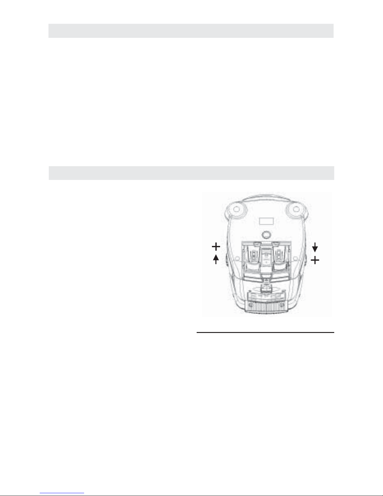
Inserting/Replacing the Battery
ALWAYS turn off the laser and the main
power switch before removing and replacing
the batteries.
Alkaline batteries are recommended for
the tool.
The battery compartment is located at the
bottom of the unit, below the power switch
and AC/DC port. Open the compartment and
replace the batteries. Note that the two pairs
of batteries are stacked.
When inserting, pay attention to the correct
polarity according to the representation on
the inside of the battery compartment.
To open the battery lid, slide lid toward the
back of the tool.
Always replace all batteries at the same time.
Only use batteries from one brand and with
the identical capacity.
• Remove the batteries from the
tool when not using it for extended
periods. When storing for extended
periods, the batteries can corrode and
discharge themselves.
Low Battery Indicator
The LED flashes yellow when 25 percent of
battery life remains (approximately five
hours). The LED flashes, and continues to
flash in a pattern of three seconds on/one
second off, until the batteries are replaced
or fail.

-9-
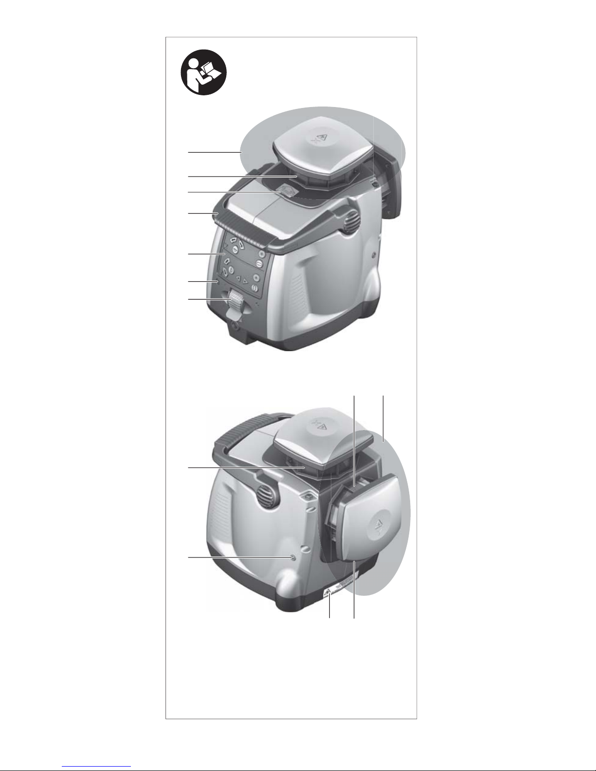
The numbering of the product features shown
refers to the illustration of the tool
on page 2.
Rotational Laser Level
1 On/off switch for rotational laser level
2 LED for operating condition
3 Control panel of the rotational laser level
4 Handle
5 Warning label, laser radiation
exit opening
6 Outlet opening of the horizontal laser
beam (X-axis)
7 Horizontal laser beam (X-axis)
8 Outlet opening of the vertical laser
beam (Y-axis)
9 Vertical laser beam (Y-axis)
10 Calibration screw, front (only for service
personnel)
11 Laser warning label
12 Calibration screw, sideward (only for
service personnel)
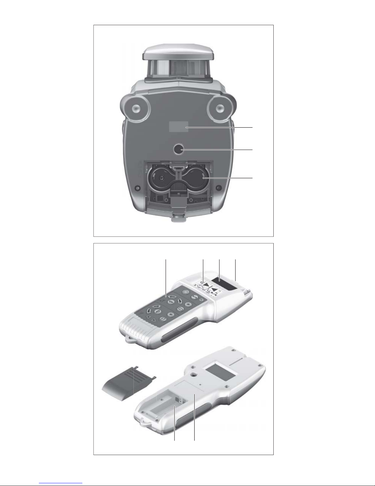
13 Serial number of the rotational laser level
14 Tripod mount 5/8- 11
15 Battery compartment, rotational
laser level
Detector/Remote Control
16 Control panel, laser receiver
17 Display
18 Reception area for the laser beam
19 Center mark
20 Serial number of laser receiver
21 Battery compartment, laser receiver
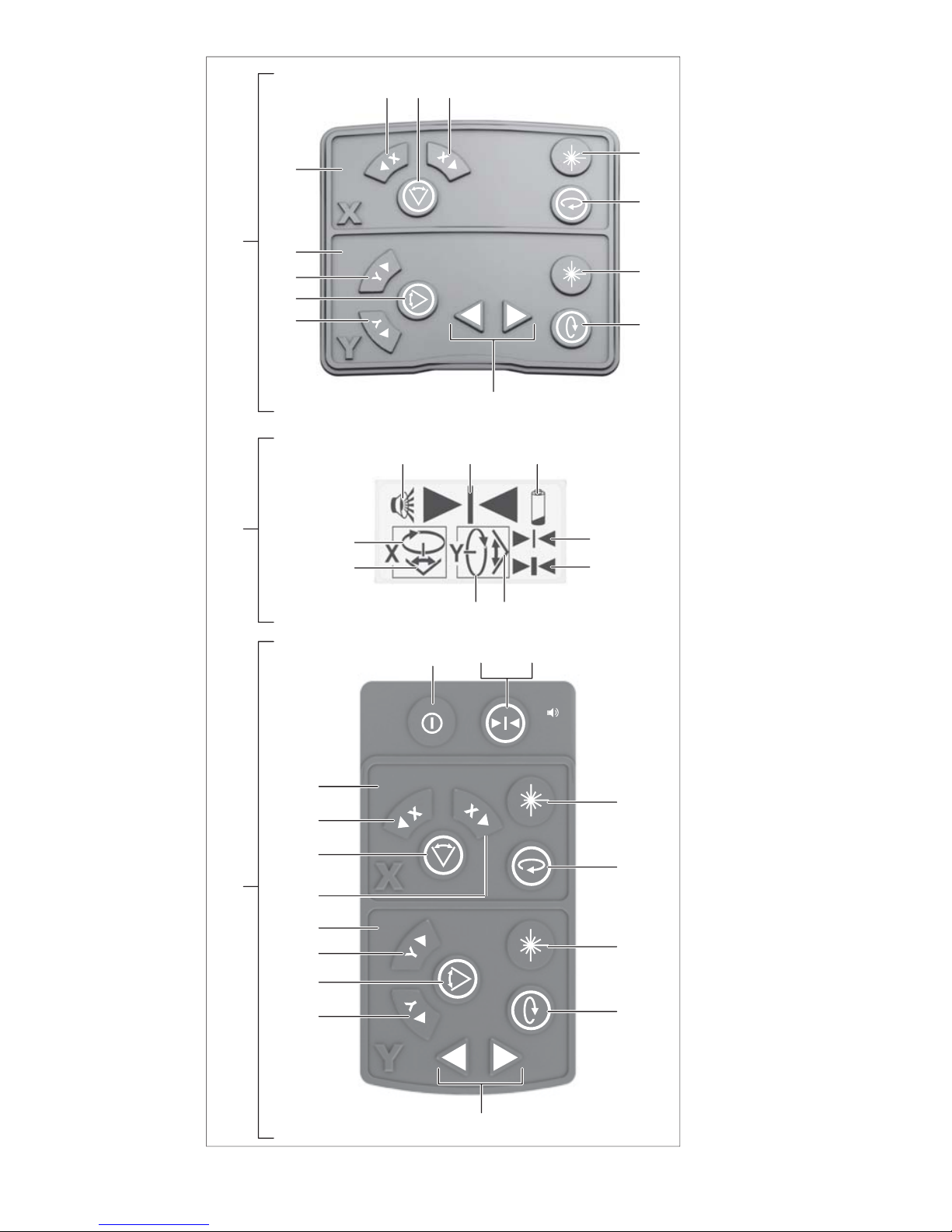
Operating controls, rotational laser level
22 Control Panel, Horizontal Laser
Beam (X-axis)
23 Button for positioning of the laser line in
counter-clockwise direction (horizontal
laser beam)
24 Button for line operation button and
selection of line length (horizontal
laser beam)
25 Button for positioning of the laser line in
clockwise direction (horizontal
laser beam)
26 On/Off button (horizontal laser beam)
27 Button for rotational operation and
selection of the rotational speed
(horizontal laser beam)
28 Control Panel, Vertical Laser
Beam (Y-axis)
29 Button for positioning of the laser line in
clockwise direction (vertical laser beam)
30 Button for line operation and selection of
line length (vertical laser beam)
31 Button for positioning of the laser line in
counter-clockwise direction (vertical
laser beam)
32 Leveling buttons (vertical laser beam)
33 Button for rotational operation and
selection of the rotational speed (vertical
laser beam)
34 On/Off button (horizontal laser beam)
Display Indications 17 on the Detector
35 Indicator for audio signal
36 Direction indicator for positioning of the
laser receiver
37 Battery indication
38 Indicator for measuring accuracy “(fine)”
39 Indicator for measuring accuracy
“(coarse)”
40 Line operation indicator (vertical
laser beam)
41 Rotational operation indicator (vertical
laser beam)
42 Line operation indicator (horizontal
laser beam)
43 Rotational operation indicator (horizontal
laser beam)
Operating Controls, Detector/Remote
Control
44 On/Off button for laser receiver
45 Button for adjustment of the
measuring accuracy
46 Audio signal button
22 Control Panel, Horizontal Laser
Beam (X-axis)
23 Button for positioning of the laser line in
counter-clockwise direction (horizontal
laser beam)
24 Button for line operation button and
selection of line length (horizontal
laser beam)
25 Button for positioning of the laser line in
clockwise direction (horizontal
laser beam)
26 On/Off button (horizontal laser beam)
27 Button for rotational operation and
selection of the rotational speed
(horizontal laser beam)
28 Control Panel, Vertical Laser
Beam (Y-axis)
29 Button for positioning of the laser line in
clockwise direction (vertical laser beam)
30 Button for line operation and selection of
line length (vertical laser beam)
Features

-10-
Article number . . . . . . . . . . . . . . 3601K61210
Number of laser points . . . . . . . . . . . . . . .
2 rotating beams, (level and plumb), with
independent and simultaneous operation.
Working Range (Diameter)
With Laser Receiver . . . .up to 1000ft(305m)
Self Leveling Range
Horizontal and Vertical . . . . . . Up to +/- 6°
Leveling Accuracy
Level (horizontal):
Minimum Factory
Accuracy . . . . . . . . . . . . . . . . . ±0.167mm/m
(±0.002004in/ft)
Typical Horizontal
Accuracy . . . . . . . . . . . . up to ±1/8”@ 100ft
(±3mm at 30m)
Plumb (vertical):
Minimum Factory
Accuracy . . . . . . . . . . . . . . . . ±0.167mm/m
(±0.002004in/ft)
Typical Vertical
Accuracy . . . . . . . . . . . . up to ±1/4”@ 100ft
(±6.4mm at 30m)
Rotation Speeds
Three Discrete Speeds: . . . . .350/600/1200
rpm +/- 10%
Dithering Settings . . . . . . . . . . . .3/10/30/45/
90/ 120°
Positioning, horizontal or vertical
(for line operation) . . . . . . . . . . . . . . . . .360°
Laser Class . . . . . . . . . . . . . . . . . .Class IIIa
Laser Type . . . . . . . . . . .635nm, <5mW max.
IP Protection . . . . . . . . . . . . . . . . . . . .IP 5X
Power . . . . . . . . . . . . . . . . . . . . . . . . . . .4 ‘D’
alkaline batteries
Weight . . . . . . . . . . . . . . . . . . . . . . . . 6.7lb
(3.05 kg)
(including 4 `D’ alkaline batteries)
Operating
Temperature Range . . . . . .14°F to + 122°F
(-10°C to + 50°C)
Storage
Temperature Range. . . . . . . .-4°F to + 158°F
(-20°C to +70°C)
Battery Life . . . . . . . . . . . . . . . 40 hrs (min)
Tripod Mount . . . . . . . . . . . . . . . . . . . .5/8-11
Remote Control with Laser
Receiver-detector
Working Range (Radius)
Laser Receiver with
Rotational Laser Level . .up to 5250ft (160m)
Remote Control . . . . . . . . up to 300ft (91m)
Measuring Accuracy
Fine Adjustment . . . . . . . +/- 1/16in @ 30ft
(+/- 1.5mm @ 10m)
Coarse Adjustment . . . . . . . +/- 1/8in@ 30ft
(+/- 3mm @ 10m)
Operating
Temperature Range . . . . . .14°F to + 122°F
(-10°C to + 50°C)
Storage
Temperature Range. . . . . . . .-4°F to + 158°F
(-20°C to +70°C)
Power . . . . . . . . . . . . .1 x 9V alkaline battery
Battery Life . . . . . . . Approximately 2000 hrs.
Stand by Operation . . . . . . . . . .after 20 min.
Remote Control
IP Protection: . . . . . . . . . . . . . . . . . . . .IP 51
Please observe the article number on the
type plate of your tool. The trade names of
the individual tools may vary.
Technical Data
31 Button for positioning of the laser line in
counter-clockwise direction (vertical
laser beam)
32 Leveling buttons (vertical laser beam)
33 Button for rotational operation and
selection of the rotational speed (vertical
laser beam)
34 On/Off button (horizontal laser beam)
Other Features
47 Laser viewing glasses
48 Laser target plate
49 Holder for laser receiver
50 Tripod*
51 Protective Case
52 Wall Mount
*The accessories illustrated or described are
not included as standard delivery.

-11-
Initial Operation
• Protect the tool against moisture and
direct sun irradiation.
• Do not subject the tool to extreme
temperatures or variations in
temperature.
As an example, do not leave it in vehicles
for longer periods. In case of large
variations in temperature, allow the tool to
adjust to the ambient temperature before
putting it into operation. In case of extreme
temperatures or variations in temperature,
the accuracy of the tool can be impaired.
• Avoid heavy impact or and prevent the
tool from falling. After heavy exterior
impact on the tool, an accuracy check
should always be carried out before
continuing to work (see “Leveling
Accuracy”).
• Switch the tool off during transport.
Switch off the leveling unit, which can be
damaged in the case of intense movement.
Setting Up the Tool
1. Place the tool on a flat surface, or set it on
a standard surveyor’s tripod, using the
built-in 5/8-11 tripod mount (located on the
bottom of the unit).
Note: Due to the high leveling accuracy, the
tool reacts sensitively to ground vibrations and
position changes. Therefore, pay attention that
the position of the tool is stable in order to
avoid operational interruptions due
to re-leveling.
Turning on the Tool
1. Turn on the tool with its power switch. The
tool immediately starts the automatic
leveling. During the leveling, LED 2 flashes
green. The tool is leveled in as soon as the
LED 2 continuously lights up green.
2. To switch on the horizontal and/or vertical
laser beam, press the On/Off button 26
and/or 34 on the control panel of the
rotational laser level 3.
Note: Each time after switching on, the tool is
in rotational operation mode with the lowest
rotational speed.
Turning off the Tool
1. To switch off the horizontal and/or vertical
laser beam, press the On/Off button 26
and/or 34 again.
2. To switch off the tool, push the On/Off
switch 1 into position O. The LED 2
goes out.
• ALWAYS turn off the laser and the main
power switch before transporting or storing
the unit.
Power Standby Mode
When commands are not received for 20
minutes, the GRL160DHV automatically
enters the power standby mode to save
battery life. The LED 2 flashes green, once
per second, to indicate power standby mode.
The timer is reset each time a button is
pressed. The power automatically turns off
after eight hours in Power Standby mode.
When the tool enters power standby mode, it
"remembers" the settings that were in effect,
and returns to these settings when a
command is issued and power returns.
Current settings are not retained when power
is turned off with the main power switch.
• To override power standby mode, press
and hold the on/off button 26 or 34 for three
seconds. The unit emits a beep and two
"chirps," confirming that automatic power
standby is disabled. After automatic power
standby is disabled, the unit continues to
operate for a maximum period of
eight hours.
• To re-enable automatic power standby,
press and hold the button 26 or 34 for three
seconds. A beep and a single "chirp"
confirm the command.
Charge-control Indicator
When the LED 2 flashes yellow, the tool can still
be operated for approx. 5h. The LED continues
to flash until the batteries are replaced or
discharged.
Working with Automatic Leveling
Position the tool on a level and firm support,
or attach it to the tripod 50.
After switching on, the automatic leveling
function automatically compensates
irregularities within the self-leveling range up
to ±6°. The leveling is finished as soon as
the tool stops beeping, the LED turns green,
and the laser beams stop flashing.
If the automatic leveling function is not
possible, e.g. because the surface on which
the tool stands deviates by more than 6° the
tool beeps, the LED flashes red once per
second, and the laser beams flash once
per second.
Operation

-12-
In this case, bring the tool to the level
position and wait for the self-leveling to take
place. As soon as the tool is within the selfleveling range of ±6° respectively, the tool
stops beeping, the LED turns green, and the
laser beams stop flashing.
In case of ground vibrations or position
changes during operation, the tool is
automatically leveled in again. To avoid
errors by moving the tool, check the position
of the laser beams with regard to the
reference points upon re-leveling.
The GRL160DHV rotary laser tool has two
basic operating modes for both the
Horizontal and Vertical laser beams. These
modes are the Rotation Mode and the Line
Dithering/Scan Mode.
Rotation Mode
The laser beam is dispersed throughout the
level or plumb plane. Rotation mode is used
under conditions where laser beam visibility
is poor or nonexistent (for example, outdoors
in daylight). It is not always possible to easily
see a rotating laser beam. A laser receiverdetector makes it possible to detect and
correctly position the rotation mode indoors
or outdoors. The Rotation Mode is the default
mode when the tool is turned on.
When the laser is first turned on, it is rotating
at 350 rpms. Press the keypad rotation mode
button 27 (Horizontal laser beam) or button
33 (Vertical laser beam) to cycle through the
medium and fast speeds, then back to slow
speed. Decrease speed to improve laser
beam visibility, especially for indoor
applications.
Note: To enter rotation mode from line
dithering/scan mode, press the keypad
rotation mode button.
Line Dithering/Scan Mode
The dithering line is a laser dot that moves
rapidly back and forth (dithers), producing a
shorter, beam that is brighter than beams in
the rotation mode. Because of the brighter
laser beam in the dithering mode, a laser
receiver-detector may not be required. The
dithering line length can easily be changed
according to application requirements in
either the level or plumb applications. The
line dithering/scan mode is normally used for
indoor applications.
A choice of six dithering line lengths are
available. The laser beam is less visible at
the longer line length. In some situations, it
may be necessary to use a laser receiverdetector to accurately locate
the beam.
When the laser is first turned on, it is rotating
at 350 rpms. To enter Line Dithering/Scan
Mode, press the keypad Line Dithering/Scan
Mode button 24 (horizontal laser beam) or 30
(vertical laser beam). Continue pressing the
Line Dithering/Scan Mode buttons to cycle
through six different line lengths. The laser
line dither can be positioned through a 360°
range in the level or plumb plane by pressing
the line position control buttons 23 or 25
(horizontal laser line) or buttons 29 or
31(vertical laser line).
Vertical Laser Beam Alignment
During rotational operation, the vertical laser
beam can be aligned on the rotational axis
(X-axis) within the range of ± 2,5°. The
default setting is vertical to the
rotational axis.
1. Press the respective button 32 until the
requested alignment is reached.
Note: If the setting range is exceeded, the
tool emits an audio signal until the laser
beam is returned back within the permitted
setting range.
Working Advice
• Always use the center of the laser point for
marking. The size of the laser point
changes with the distance.
• Working with the remote control. When
pressing the operating controls it is
possible to bring the tool out of its level
position, so that the rotation is briefly
interrupted. This effect can be prevented
by applying the laser receivers’
Remote-control function.
When working with the remote control, pull
the antenna out of the laser receiver.
Operating Modes - Rotation and Line Dithering/Scan Mode

-13-
Out of Level Indication
Out-of-level indicators alert you if the unit is
not on a level surface or if it is out of selfleveling range:
• The LED flashes red once per second
• The laser beam stops rotating (if in rotation
mode) or dithering (if in dithering/dot mode)
and flashes a laser dot in sync with the LED
• The beeper sounds in sync with the laser
beam and LED
Reposition the tool to ensure that it is within the
self-leveling range of ±6°. Once the unit is
within self-leveling range, it stops beeping, the
LED turns green, and the laser beam stops
flashing. The tool resumes the mode of the last
command issued.
Note: When the laser beam is switched off,
the alert is indicated only by the flashing LED
and the audio signal.
Note: The out-of-level indicator overrides all
other indicators. If the laser tool is in low
battery or power standby mode and becomes
out of level, the out-of-level indicator overrides
the low battery or power standby mode
indicator.
Influences on Accuracy
The ambient temperature has the greatest
influence. Especially temperature differences
occurring from the ground upward can divert
the laser beam.
As thermal fluctuation is largest close to the
ground, the tool, if possible, should be
mounted on a commercially available tripod
and placed in the center of the working area.
Apart from exterior influences, device specific
influences (such as heavy impact or drop) can
lead to deviations. Therefore, check the
accuracy of the tool each time before starting
your work.
Should the tool exceed the maximum
deviation during one of the tests, see
recalibration procedure or have it recalibrated
by a Bosch after-sales service center.
Leveling
In the level position, the tool automatically
self-levels within ±6°. When the tool is turned
on. Once the tool is level, the LED turns to a
steady green, and the beeping stops. Press
button 27 (Horizontal laser beam) or button
33 (Vertical laser beam) the laser then begins
rotating at a slow speed.
Calibration
Although the GRL 160DHV laser tools are
calibrated to specification before leaving the
factory, they contain many precision-machined
parts that may be affected if subject to abuse.
Therefore, if a unit is dropped or sustains
significant impact, check its calibration. It is
also recommended that the tool be
periodically calibrated, as a normal
maintenance procedure.
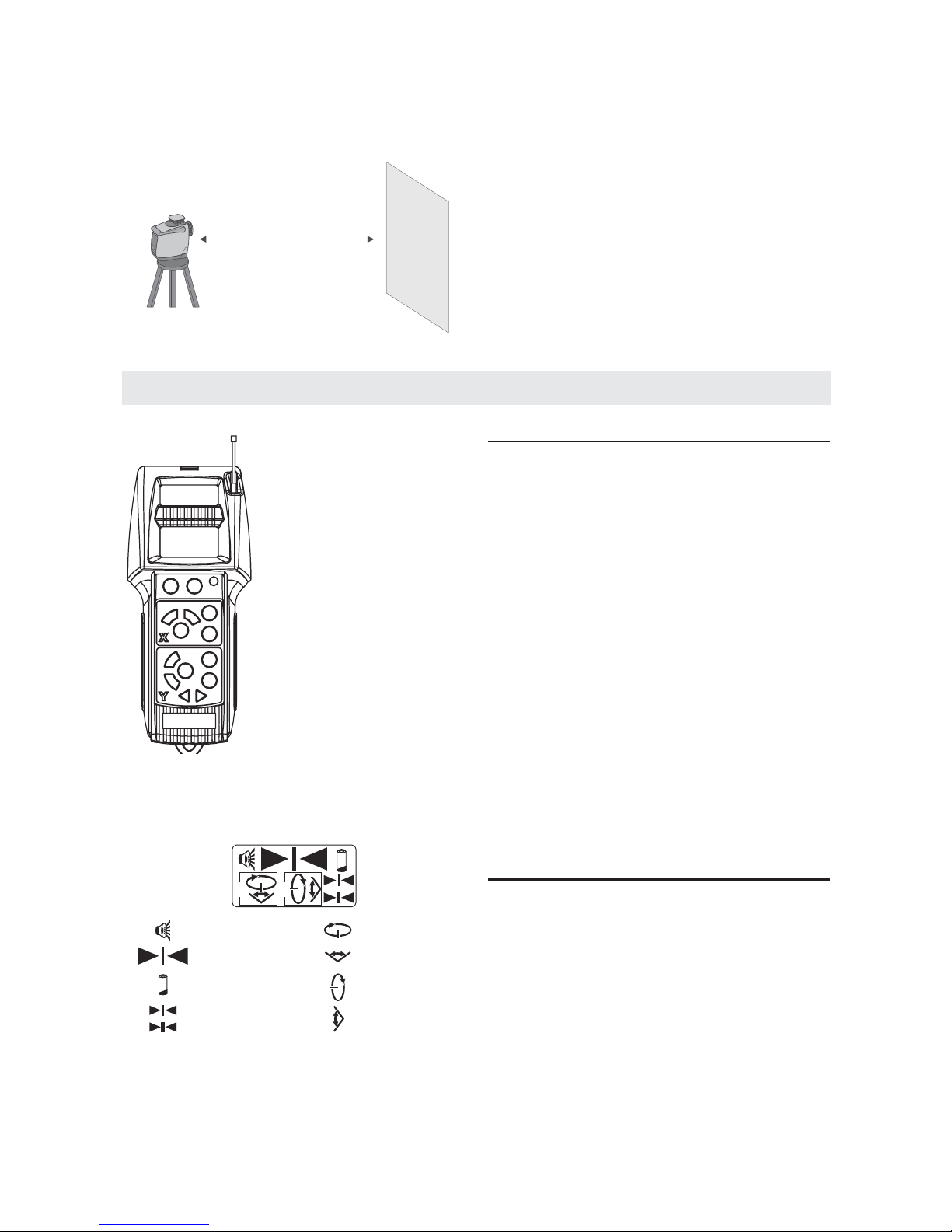
To Calibrate the GRL160DHV:
1. Select a site for calibration that allows the
unit to be placed about 50 ft. (15m) away
from a smooth vertical surface, such as a
wall. Use an Allen wrench to remove the
calibration port covers on the side and
front of the unit. Store the calibration port
covers in a safe place.
2. Set the unit on a level surface at one end
of the range. Place the unit with the side
facing the wall. Ensure the calibration
port faces away from the wall.
3. Turn on the unit with its power switch 1,
then press the keypad laser level
(horizontal) on/off button 26. Select Line
Dither/Scan mode (at the shortest line
length) for best laser beam visibility. If the
beam is not visible, use the laser detector
to locate the beam.
Leveling Accuracy

-14-
4. Mark the laser beam height (center) on the
vertical surface of the wall, as A.
5. Rotate the tool 180°, taking care not to
change its height. The tool should be
positioned with its opposite side facing the
same vertical wall as in step 2. Use the
level (horizontal) Line Dither/Scan position
arrows 23 and 25 to position the laser
beam on the original wall.
6. Mark the height of the laser beam on the
same vertical surface, as B. If B is
positioned at the same height as A,
proceed to step 11. Otherwise, continue to
step 7. The goal of the next few steps is to
position the level laser beam at a height
halfway between A and B
7. Turn off the laser beam and the tool.
Caution: The laser beam must be turned off
and the main power switch in the off position
before proceeding to the next step
8. Insert an Allen wrench into the side
calibration port and locate the calibration
screw. Rotate it clockwise to lower the
beam, or counterclockwise to raise
the beam.
9. Remove the Allen wrench from the
calibration port. Turn on the power, turn on the
level laser beam, then check the height of the
laser beam. Repeat steps 7 and 8 until the
beam is at a height exactly halfway between
A. and B.
Caution: The Allen wrench must be removed
from the calibration port before turning on
the power.
10. Mark this calibrated point on the vertical
surface, as C.
11. Repeat steps 3-7 to confirm the position of
C, then proceed to step 12.
12. Rotate the base unit 90° and position it
with the front facing the vertical surface.
Mark the height of the laser beam, as D.
13. Compare the height of D with C. If the
height of D matches the height of C,
calibration is complete. Turn the power
switch to the off position. Reattach the
calibration port covers, then resume
normal operation. If the height of D does
not match the height of C, proceed to
step 14.
14. Turn off the laser beam and power to the
unit.
Caution: The laser beam must be turned off
and the power switch in the off position before
proceeding to the next step.
15. Insert an Allen wrench into the front
calibration port and locate the calibration
screw. Rotate it clockwise to lower the
beam, or counterclockwise to raise
the beam.
50 ft. (15m)
A
*
50 ft. (15 m)
50 ft. (15m)
Y
B
*
50 ft. (15 m)
50 ft. (15m)
B
A
C
*
Y
50 ft. (15 m)
50 ft. (15m)
*
D
C
50 ft. (15 m)
-15-
16. Remove the Allen wrench from the
calibration port. Turn on the power, turn on
the level laser beam, then check the
height of the laser beam. Repeat steps 14
and 15 until the beam is at the height of C.
Caution: The Allen wrench must be removed
from the calibration port before turning on
the power.
Calibration is complete.
17. Turn the power switch to the off position.
Reattach the calibration port covers, then
resume normal operation.
Note: Complete calibration of the level laser
beam automatically calibrates the plumb laser
beam. Separate calibration of the plumb laser
beam is not required.
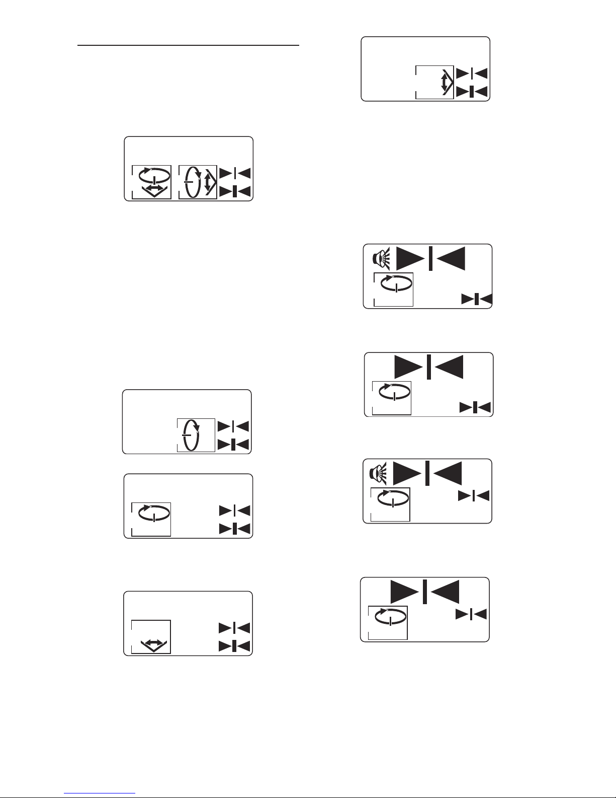
Using the Remote Control / Receiver-Detector
The GRL160DHV can also
be operated using the
RCR1 Remote Control /
Receiver. Its receiving
(detecting) function
responds better to the
GRL160DHV laser tools
rather than any other laser
receiver-detector. The
RCR1 allows accurate laser
beam detection outdoors or
under other conditions
when the beam is difficult to
see. The following diagram
illustrates the RCR1
remote control.
The following diagram illustrates RCR1’s LCD
display icon.
Starting Operation of the Laser Receiver
• Protect the laser receiver against moisture.
• Do not subject the laser receiver to extreme
temperatures or variations in temperature.
As an example, do not leave it in vehicles for
longer periods. In case of large variations in
temperature, allow the laser receiver to adjust to
the ambient temperature before putting it into
operation. In case of extreme temperatures or
variations in temperature, the accuracy of the
laser receiver can be impaired.
Under unfavorable light conditions (bright
environment, direct sunlight) and for larger
distances, use the laser receiver for improved
finding of the laser beam. When working with the
laser receiver, select rotational operation with the
highest rotational speed.
Position the laser receiver at least 50cm away
from the rotational laser level. Position the laser
receiver in such a manner that the laser beam
can reach the reception area 18. Set the highest
rotational speed on the rotational laser level.
Attaching the RCR1 to the Bracket
The RCR1 can be attached to the its bracket
with either a level or plumb allocation
depending on whether it is being used to
locate the level or plumb laser beam.
The bracket’s clamp is used to attach it to a
grade/leveling rod.
X
Y
Low Battery
Indicator
Beeper On/Off
Level Line
Dither/Scan Mode
Level Spin Mode/
Speed Select
Plumb Spin Mode/
Speed Select
Fine Resolution
Coarse Resolution
Plumb Line
Dither/Scan Mode
Detector Laser
Beam Locator
Detector LCD Display
50 ft. (15m)
D
C
50 ft. (15 m)
Operation
1. Activate the RCR1 by pressing its power
on/off button. The unit emits a single beep,
and icons in the lower portion of the LCD
display appear, showing all available
options. This confirms that the unit is
activated, but the GRL160DHV and RCR1
have not been turned on.
RF remote control / Laser detector activated
2. Turn on the tool by pressing the laser
on/off button from the keypad. As soon as
one or both of the lasers are turned on,
the displayed icons confirm the selected
laser(s) (level, plumb, or both) and mode
(Spin or Line Dither/Scan). The level and
plumb lasers start up in Spin mode, at the
slowest speed.
Note: The LCD display shows the laser modes
for commands transmitted to the tool from the
RF remote control. Commands made from the
tool controls are not shown on the RF remote
control/laser receiver-detector LCD display.
Plumb laser, Spin mode, Detector off
Level laser, Spin mode, Detector off
Press the Line Dither/Scan button 24 or 30
again to change to Line Dither/Scan mode.
Level laser, Line Dither/Scan Mode,
Detector off
Plumb laser, Line Dither/Scan Mode,
Detector off
3. Laser Detection To turn on the laser
detector, press the Coarse/Fine Select
button 45. On startup, the laser detector
resolution is coarse, with the beeper on
indicated by the icons on LCD display.
Continue pressing the Coarse/Fine 45
Select button to cycle through the following
options:
Beeper on, Laser detector on, Coarse
resolution, Level laser, Spin mode
Beeper off, Laser detector on, Coarse
resolution, Level laser, Spin mode
Beeper on, Laser detector on, Fine resolution,
Level laser, Spin mode
Beeper off, Laser detector on, Fine resolution,
Level laser, Spin mode
-16-
X
Y
Y
X
X
Y
X
X
X
X
-17-
Laser detector power off, Level laser,
Spin mode
4. Locate the laser beam, using the red
sensor panel on the RCR1. As the laser
beam is approached, a single arrow points
in the direction of the beam. The base unit
emits sounds to aid in locating the laser
beam:
• Rapid beep - Indicates that the laser
detector is pointed overly high or far to
the left or right.
• Continuous tone - Indicates that the
laser detector is pointed directly toward
the laser beam.
5. Center the beam by moving the laser
detector in the direction of the arrow.
When the beam is aligned with the center
of the detector panel, both arrows on the
LCD display are lit and the beep is
continuous, indicating that it is properly
centered.
Note: Laser detector orientation depends on
whether it is being used to locate the level or
plumb laser beam.
6. To turn off the RCR1, press its power
On/Off button. There is a double beep for
confirmation, the LCD display becomes
blank, and the lasers shut off.
Charge-control Indicator
When the symbol for the battery indication 37
is indicated on the display 17, the laser
receiver can still be operated for approx. 4
hours.
X
Level laser detection
Plumb laser detection
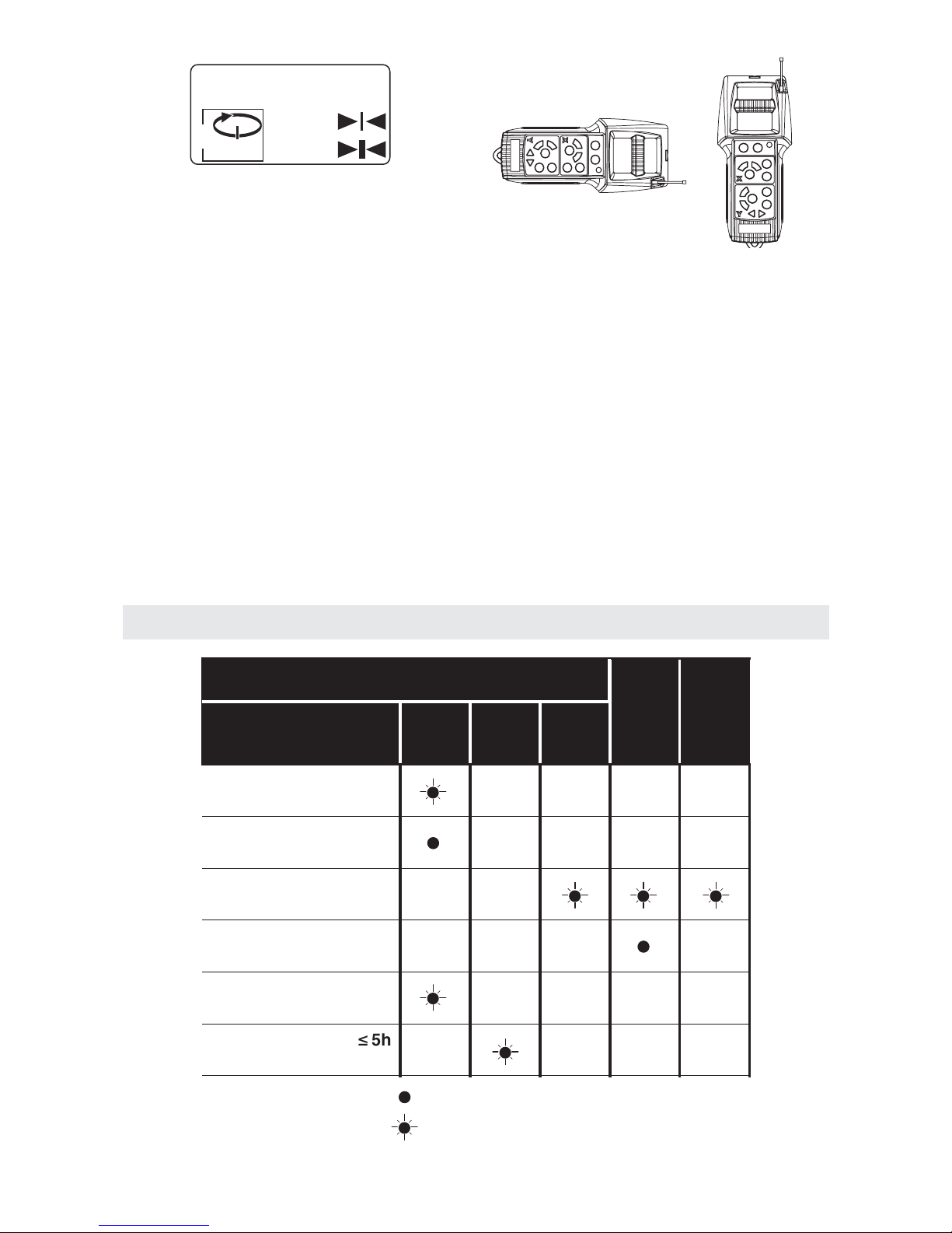
LED Indications
Switching on the tool
Tool leveled in/ready
for operation
Battery voltage for ² 5h
operation
Self-Leveling range
exceeded
Leveling range of the
vertical laser exceeded
Tool In stand-by
operation
Audio Signal
Laser Beam
Continuous lighting and audio signal
Flashing and single audio signals
Green RedYellow
LED
 Loading...