


OBJ_DOKU-40143-002.fm Page 1 Friday, August 5, 2016 2:20 PM
Robert Bosch Power Tools GmbH
70538 Stuttgart
GERMANY
GLM 100 C Professional
www.bosch-pt.com
1 609 92A 28X (2016.08) I / 89
en Original instructions cn tw
ko
th
id Petunjuk-Petunjuk untuk Penggunaan Orisinal
vi Bản gốc hướng dẫn sử dụng

OBJ_BUCH-2201-002.book Page 2 Friday, July 22, 2016 9:58 AM
2 |
English . . . . . . . . . . . . . . . . . . . . . . . . . . . . . . . . . . . . . . |
. . . .Page |
8 |
. . . . . . . . . . . . . . . . . . . |
. . |
20 |
. . . . . . . . . . . . . . . . . . . |
. . . |
31 |
. . . . . . . . . . . . . . . . . . . . . . . |
. |
41 |
. . . . . . . . . . . . . . . . . . . . . . . . . . . . . |
. . . . |
52 |
Bahasa Indonesia . . . . . . . . . . . . . . . . . . . . . . . . . . . . . . |
Halaman |
64 |
Tiếng Việt . . . . . . . . . . . . . . . . . . . . . . . . . . . . . |
Trang |
76 |
1 609 92A 28X | (22.7.16) |
Bosch Power Tools |

OBJ_BUCH-2201-002.book Page 3 Friday, July 22, 2016 9:58 AM |
|
|
|
||||||
3 | |
|
|
|
|
|
|
|
|
|
|
i |
k |
l |
|
|
|
|
n |
m |
h |
|
|
|
|
|
|
|
||
|
|
|
|
|
|
|
|
|
|
g |
|
|
|
|
|
|
|
|
|
|
|
|
|
|
|
|
a |
|
|
f |
|
|
|
|
|
|
|
|
|
e |
|
|
|
|
|
|
b |
|
|
d |
|
|
|
|
|
|
|
|
|
|
|
|
|
|
|
|
c |
|
|
13 |
|
|
|
|
|
|
|
|
|
12 |
|
|
|
|
|
|
|
|
|
11 |
|
|
|
|
|
|
|
|
|
10 |
|
|
|
|
|
|
|
|
|
|
|
|
|
|
|
|
|
|
14 |
|
|
|
|
|
|
2 |
1 |
22 |
15 |
|
|
|
|
|
|
|
|
||
|
|
|
|
|
3 |
21 |
|
|
|
|
|
|
|
|
20 |
|
|
||
|
|
|
5 |
4 |
|
|
|
||
|
|
|
19 |
|
|
|
|
||
|
|
7 |
6 |
18 |
|
|
|
|
|
9 |
8 |
17 |
|
|
|
|
|
||
|
|
|
|
|
|
||||
|
|
|
|
|
|
|
|||
|
|
|
|
|
|
|
|
||
100 C |
|
|
|
|
|
|
|
|
|
PGLMrofessional |
|
|
|
|
|
|
|
|
|
|
26 |
|
|
|
|
|
|
|
16 |
|
|
|
|
|
|
|
|
|
|
|
25 |
|
|
|
|
|
|
|
23 |
|
|
|
|
|
|
|
|
|
|
GLM 100 C |
|
|
|
|
|
|
|
|
24 |
|
|
|
|
|
|
|
|
|
|
1 609 92A 28X | (22.7.16) |
|
|
|
|
|
|
|
|
Bosch Power Tools |
OBJ_BUCH-2201-002.book Page 4 Friday, July 22, 2016 9:58 AM |
4 | |
A |
B |
|
C |
1 |
|
|
||
|
|
max |
|
|
|
|
1 |
|
|
|
X |
|
|
min |
|
D |
1 |
E |
1 |
|
|||
2 |
|
||
|
1 |
|
1 |
|
|
X |
|
|
|
|
|
|
2 |
|
X |
1 609 92A 28X | (22.7.16) |
|
Bosch Power Tools |
|
OBJ_BUCH-2201-002.book Page 5 Friday, July 22, 2016 9:58 AM |
|
5 | |
|
F |
G |
|
B3 |
|
B1 |
|
B2 |
|
A |
H |
|
180º |
90º |
180º |
I |
|
28 |
27 |
|
27 |
|
|
|
|
|
3 |
|
|
2 |
|
|
3 |
|
|
2 |
|
1 |
|
1 609 92A 28X | (22.7.16) |
|
Bosch Power Tools |
OBJ_BUCH-2201-002.book Page 6 Friday, July 22, 2016 9:58 AM
6 |
J
K |
1 |
|
|
|
180º |
|
180º |
90º |
90º |
1 609 92A 28X | (22.7.16) |
Bosch Power Tools |
OBJ_BUCH-2201-002.book Page 7 Friday, July 22, 2016 9:58 AM
| 7
29 |
30 |
31 |
BT 150 |
1 608 M00 05B |
2 607 001 391 |
0 601 096 B00
27
0 601 079 000
Bosch Power Tools |
1 609 92A 28X | (22.7.16) |
 OBJ_BUCH-2201-002.book Page 8 Friday, July 22, 2016 9:58 AM
8 | English
English
Safety Notes
All instructions must be read and observed in order to
work safely with the measur-
ing tool. The integrated protections in the measuring
tool may be compromised if the measuring tool is not used in accordance with the instructions provided. Never make warning signs on the measuring tool unrecognisable.
STORE THESE INSTRUCTIONS IN A SAFE PLACE AND INCLUDE THEM WITH THE MEASURING TOOL WHEN GIVING IT TO A THIRD PARTY.
Caution – The use of other operating or adjusting equipment or the application of other processing methods than those mentioned here can lead to dangerous radiation exposure.
The measuring tool is provided with a warning label (marked with number 21 in the representation of the measuring tool on the graphics page).
If the text of the warning label is not in your national language, stick the provided warning label in your national language over it before operating for the first time.
Do not direct the laser beam at persons or animals and do not stare into the di-
rect or reflected laser beam yourself, not even from a distance. You could blind somebody, cause accidents or damage your eyes.
If laser radiation strikes your eye, you must deliberately close your eyes and immediately turn your head away from the beam.
Do not use the laser viewing glasses as safety goggles.
The laser viewing glasses are used for improved visualisation of the laser beam, but they do not protect against laser radiation.
Do not use the laser viewing glasses as sun glasses or in traffic. The laser viewing glasses do not afford complete UV protection and reduce colour perception.
Do not make any modifications to the laser equipment.
Have the measuring tool repaired only through qualified specialists using original spare parts. This ensures that the safety of the measuring tool is maintained.
Do not allow children to use the laser measuring tool without supervision. They could unintentionally blind other persons or themselves.
Do not operate the measuring tool in explosive environ-
ments, such as in the presence of flammable liquids, gases or dusts. Sparks can be created in the measuring tool which may ignite the dust or fumes.
Protect the measuring tool against heat, e.g.,
against continuous intense sunlight, fire, water, and moisture. Danger of explosion.
In case of damage and improper use of the battery, va-
pours may be emitted. Ventilate the area and seek medical help in case of complaints. The vapours can irritate the respiratory system.
Caution! When using the measuring tool with Bluetooth®, interference with other devices and systems, airplanes and medical devices (e. g., cardiac pacemakers, hearing aids) may occur. Also, the possibility of humans and animals in direct vicinity being
harmed cannot be completely excluded. Do not use the measuring tool with Bluetooth® in the vicinity of medical devices, petrol stations, chemical plants, areas
where there is danger of explosion, and areas subject to blasting. Do not use the measuring tool with Bluetooth® in airplanes. Avoid operation in direct vicinity of the body over longer periods.
The Bluetooth® word mark and logos are registered trademarks owned by Bluetooth SIG, Inc. and any use of such marks by Robert Bosch Power Tools GmbH is under license.
Safety Warnings for Battery Chargers
This battery charger can be used by children aged from 8 years and above and persons with reduced physical, sensory or mental capabilities or lack of experience and knowledge if they have been given supervision or instruction concerning use of the battery charger in a
safe way and understand the hazards involved. Otherwise, there is danger of operating errors and injuries.
1 609 92A 28X | (22.7.16) |
Bosch Power Tools |
OBJ_DOKU-40266-002.fm Page 9 Thursday, August 18, 2016 11:15 AM
Supervise children during use,
cleaning and maintenance. This will ensure that children do not play with the charger.
Only charge Bosch lithium-ion batteries with a capacity of
1.25 Ah or more (1 battery cells or more). The battery voltage must match the battery charging voltage of the charger. Do not charge non-
rechargeable batteries. Otherwise there is danger of fire and explosion.
Keep the battery charger away from rain or moisture. Penetration of water in the battery charger increases the risk of an electric shock.
Charge the measuring tool only with the supplied charger.
Do not operate the battery charger on easily inflamma-
ble surfaces (e. g., paper, textiles, etc.) or surroundings. The heating of the battery charger during the charging process can pose a fire hazard.
Keep the battery charger clean. Contamination can lead to danger of an electric shock.
Before each use, check the battery charger, cable and plug. If damage is detected, do not use the battery charger. Never open the battery charger yourself.
Have repairs performed only by a qualified technician and only using original spare parts. Damaged battery chargers, cables and plugs increase the risk of an electric shock.
Product Description and Specifications
While reading the operating instructions, unfold the graphics page of the product and leave it open.
Intended Use
The measuring tool is intended for measuring distances, lengths, heights, clearances, grades and for the calculation of areas and volumes. The measuring tool is suitable for measuring indoors and outdoors.
The measuring results can be transmitted to other devices via Bluetooth® and USB data port (not when operating the measuring tool in the R60 Professional measuring rail).
Bosch Power Tools
|
English | 9 |
|
|
||
Technical Data |
|
|
|
|
|
|
|
|
|
|
|
Digital Laser Measure |
GLM 100 C |
|
|
||
Article number |
3 601 K72 7.. |
|
|
||
Distance measurement |
|
|
|
|
|
Measuring range (max.) |
100 m A) |
|
|
||
Measuring range (typical) |
0.05 – 80 m B) |
|
|
||
Measuring range (typical under |
45 m C) |
|
|
||
unfavourable conditions) |
|
|
|||
Measuring accuracy (typical) |
± 1.5 mm B) |
|
|
||
Measuring accuracy (typical under |
± 2.5 mm C) |
|
|
||
unfavourable conditions) |
|
|
|||
Lowest indication unit |
0.1 mm |
|
|
||
Indirect Distance Measurement |
|
|
|
|
|
and Vial |
|
|
|
|
|
Measuring range |
0 ° – 360 ° (4 x 90 °) D) |
|
|
||
Inclination measurement |
|
|
|
|
|
Measuring range |
0 ° – 360 ° (4 x 90 °) D) |
|
|
||
Measuring accuracy (typical) |
±0.2 ° E)/G) |
|
|
||
Lowest indication unit |
0.1 ° |
|
|
||
General |
|
|
|
|
|
Operating temperature |
– 10 ° C ... + 50 ° C F) |
|
|
||
Storage temperature |
– 20 ° C ... +50 ° C |
|
|
||
Allowable charging temperature |
+5 ° C ... +40 ° C |
|
|
||
range |
|
|
|||
Relative air humidity, max. |
90 % |
|
|
||
Laser class |
2 |
|
|
||
Laser type |
635 nm, < 1 mW |
|
|
||
Laser beam diameter (at 25 ° C) |
|
|
|
|
|
approx. |
6 mm J) |
|
|
||
– at 10 m distance |
|
|
|||
– at 80 m distance |
48 mm J) |
|
|
||
Setting accuracy of the laser to the |
|
|
|
|
|
housing, approx. |
± 2 mm/m G) |
|
|
||
– Vertical |
|
|
|||
– Horizontal |
± 10 mm/m G) |
|
|
||
Automatic switch-off after approx. |
20 s |
|
|
||
– Laser |
|
|
|||
– Measuring tool (without measure- |
5 min |
|
|
||
ment) |
|
|
|||
Weight according to EPTA- |
0.14 kg |
|
|
||
Procedure 01:2014 |
|
|
|||
Dimensions |
51 x 111 x 30 mm |
|
|
||
Degree of protection |
IP 54 (dust and splash |
|
|
||
|
water protected) |
|
|
||
Data transmission |
|
|
|
|
|
Bluetooth® |
Bluetooth® 4.0 |
|
|
||
|
(Classic and Low |
|
|
||
|
Energy) I) |
|
|
||
Micro USB cable |
USB 2.0 |
|
|
||
– Charging voltage |
5.0 V |
|
|
|
|
|
|
|
|||
– Charging current |
500 mA |
|
|
||
|
1 609 92A 28X | (18.8.16) |
|
|
||
|
|
|
|
|
|
|
|
|
|
|
|
|
|
|
|
|
|
OBJ_BUCH-2201-002.book Page 10 Friday, July 22, 2016 9:58 AM
10 | English
Digital Laser Measure |
GLM 100 C |
Battery |
Li-Ion |
Rated voltage |
3.7 V |
Capacity |
1.25 Ah |
Number of battery cells |
1 |
Single measurements per battery |
25000 H) |
charge, approx. |
Digital Laser Measure |
GLM 100 C |
||
Battery Charger |
|
|
|
Article number |
2 609 120 4.. |
||
Charging time |
approx. 3.5h |
||
Output voltage |
5.0 V |
|
|
|
|||
Charging current |
500 mA |
||
Protection class |
/ II |
||
A)For measurements from the rear measuring-tool edge, the operating range increases the better the laser light is reflected from the surface of the target (dispersive, not reflective) and the brighter the laser point is with respect to the ambient brightness (indoors, twilight). For distances greater than 80 m, we recommend using a retroreflective target plate (accessory). For distances below 20 m, a retroreflective target plate should not be used, as it can lead to measuring errors.
B)For measurements from the rear measuring-tool edge, 100 % reflectance of the target (e. g., a white-painted wall), weak backlight and 25 °C operating temperature. Additionally, a deviation influence of ±0.05 mm/m must be taken into account.
C)For measurements from the rear measuring-tool edge, 10 – 100 % reflectance of the target, strong backlight and – 10 °C to + 50 °C operating temperature. Additionally, a deviation influence of ±0.29 mm/m must be taken into account.
D)For measurements with the rear side of the unit as reference, the max. measuring range is ± 60°.
E)After calibration at 0 ° and 90 ° with an additional grade error of ±0.01 °/degree to 45 ° (max.).
F)In the continuous measurement function, the maximum operating temperature is + 40 °C.
G)At 25 °C operating temperature
H)For a new and charged battery without display illumination, Bluetooth® and tone signal.
I)For Bluetooth® low energy devices, establishing a connection may not be possible, depending on model and operating system. Bluetooth® devices must support the SPP profile.
J)The width of the laser line depends on the surface characteristics and on the ambient conditions.
The measuring tool can be clearly identified with the serial number 20 on the type plate.
Product Features
The numbering of the product features shown refers to the illustration of the measuring tool on the graphic page.
1 Display
2 Measuring button
3 Button for grade measurement / calibration **
4 Button for clearing the internal memory / On/Off ** 5 Minus button
6 Button for result / timer function **
7 Button for measured-value list / storage of constant ** 8 Button for function mode / basic settings **
9 Positioning pin
10Button for selection of the reference level
11Plus button
12Button for length, area and volume measurement
13Bluetooth® button
14Cover, micro USB port
15Micro USB port
16Fixture for carrying strap
17Reception lens
18Laser beam outlet
191/4" thread
20Serial number
21Laser warning label
22QR-Code (product information)
23Charge connector
24Battery charger
25Micro USB cable
26Protective pouch
27Measuring rail*, ***
28Locking lever for measuring rail
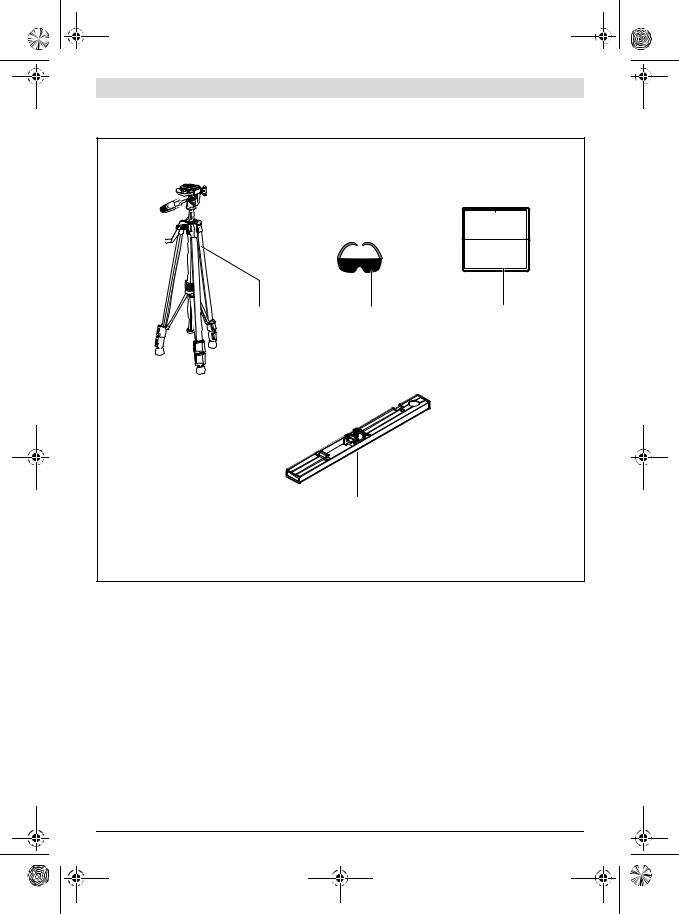
29Tripod*
30Laser viewing glasses*
31Laser target plate*
* The accessories illustrated or described are not included as standard delivery.
**Keep button pressed to call up the extended functions.
***When operating the measuring tool in the measuring rail 27, data transmission is not possible.
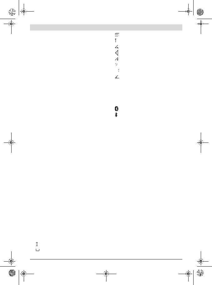
Display Elements
a Measured-value lines b “ERROR” indication c Result line
d Digital vial / position of measured-value list entry e Measured-value list indicator
f Measuring functions
Length measurement
Area/surface measurement
Volume measurement Continuous measurement
1 609 92A 28X | (22.7.16) |
Bosch Power Tools |
OBJ_BUCH-2201-002.book Page 11 Friday, July 22, 2016 9:58 AM
1 |
Indirect height measurement |
2 |
Double indirect height measurement |
1 |
|
1Indirect length measurement
Timer Function
Wall-surface measurement
Inclination Measurement
g Battery charge-control indicator
hLaser, switched on
i Measurement reference level k Temperature warning
l Bluetooth® switched on
Bluetooth® activated, connection established
Bluetooth® activated, no connection established
m Charging procedure
n Slow charging procedure
The Bluetooth® word mark and logos are registered trademarks owned by Bluetooth SIG, Inc. and any use of such marks by Robert Bosch Power Tools GmbH is under license.
Assembly
Battery Charging
Do not use a different battery charger. The battery charger provided is matched to the lithium-ion battery installed in your measuring tool.
Observe the mains voltage! The voltage of the power source must correspond with the data on the type plate of the battery charger.
Note: The battery is supplied partially charged. To ensure full battery capacity, completely charge the battery before using for the first time.
The lithium-ion battery can be charged at any time without reducing its service life. Interrupting the charging procedure does not damage the battery.
When the bottom segment of the battery charge-control indicator g flashes, only a few more measurements can be carried out. Charge the battery.
When the frame around the segments of the battery chargecontrol indicator g flashes, measurements are no longer possible. Continued use of the measuring tool is only possible for a short period (e. g., for checking entries in the measured-val- ue list, performing a calculation, etc.). Recharge the battery.
The charge procedure begins as soon as the mains plug of the battery charger is plugged into the socket outlet and the charge connector 23 is plugged into socket 15.
The battery charge-control indicator g indicates the charging progress. During the charging procedure, the segments flash one after the other. When all segments of battery charge-con-
Bosch Power Tools
English | 11
trol indicator g are displayed, the battery is completely charged.
Disconnect the battery charger from the mains supply when not using it for longer periods.
Additionally, the battery can also be recharged via a USB port. For this, connect the measuring tool to a USB port using the micro USB cable. In USB operation (recharging, data transmission), the charging duration n can be significantly prolonged.
The measuring tool cannot be used independently during the charging procedure. Usage is possible only in combination with a USB connection and the available software.
The Bluetooth® function switches off during the charging procedure. Existing connections to other devices are interrupted. This can lead to data loss.
Protect the battery charger against moisture!
Notes for Optimum Handling of the Battery in the Measur-
ing Tool
Store the measuring tool only within the allowable temperature range, see “Technical Data”. As an example, do not leave the measuring tool in a vehicle in summer.
A significantly reduced working period after charging indicates that the battery is used and must be replaced.
Observe the notes for disposal.
Operation
Initial Operation
Do not leave the switched-on measuring tool unattended and switch the measuring tool off after use. Other persons could be blinded by the laser beam.
Protect the measuring tool against moisture and direct sun light.
Do not subject the measuring tool to extreme temperatures or variations in temperature. As an example, do not leave it in vehicles for a long time. In case of large variations in temperature, allow the measuring tool to adjust to the ambient temperature before putting it into operation. In case of extreme temperatures or variations in temperature, the accuracy of the measuring tool can be impaired.
Avoid heavy impact to or falling down of the measuring tool. After severe exterior effects to the measuring tool, it is recommended to carry out an accuracy check (see “Accuracy Check and Calibration of the Grade Measurement” and “Accuracy Check of the Distance Measurement” on page 16) each time before continuing to work.
Switching On and Off
For switching on the measuring tool, the following possibilities are given:
–Press the On/Off button 4: The measuring tool is switched on and is in length measurement mode. The laser is not activated.
–Press the measuring button 2: Measuring tool and laser are switched on. The measuring tool is in length measurement
1 609 92A 28X | (22.7.16)
OBJ_BUCH-2201-002.book Page 12 Friday, July 22, 2016 9:58 AM
12 | English
mode. When the measuring tool is inserted in the measuring rail 27, the grade measurement function is activated.
Do not point the laser beam at persons or animals and do not look into the laser beam yourself, not even from a large distance.
To switch off the measuring tool, press the On/Off button 4 for a few seconds.
When no button on the measuring tool is pressed for approx. 5 minutes, the measuring tool automatically switches off to save the batteries/rechargeable batteries.
When the angle is not changed for approx. 5 minutes when in the “Grade measurement” operating mode, the measuring tool automatically switches off to save the batteries/rechargeable batteries.
When switching off automatically, all stored values are retained.
Measuring Procedure
When the measuring tool is inserted in the measuring rail 27, it is always in the length measurement or grade measurement function after switching on by pressing the measuring button 2. Other measuring modes can be switched to by pressing the respective function/mode button (see “Measuring Functions”, page 13).
After switching on, the rear edge of the measuring tool is preset as the reference level for the measurement. By pressing the reference level button 10, the reference level can be changed (see “Selecting the Reference Level”, page 12).
Place the measuring tool with the selected reference plane against the desired starting point of the measurement (e. g. a wall).
Briefly press the measuring button 2 to switch on the laser beam.
Do not point the laser beam at persons or animals and do not look into the laser beam yourself, not even from a large distance.
Aim the laser beam at the target surface. Briefly press the measuring button 2 again to initate the measurement.
When the laser beam is switched on permanently, the measurement already starts after the first actuation of the measuring button 2. In continuous measurement mode, the measurement starts immediately upon switching on.
The measured value typically appears after 0.5 seconds and at the latest after 4 seconds. The duration of the measurement depends on the distance, the light conditions and the reflection properties of the target surface. The end of the measurement is indicated by a signal tone. The laser beam is switched off automatically upon completion of the measurement.
When no measurement takes place approx. 20 seconds after collimating, the measuring tool automatically switches off to save the battery.
1 609 92A 28X | (22.7.16)
Selecting the Reference Level (see figure A)
For the measurement, you can select between four reference planes:
–The rear edge of the measuring tool or the front edge of the 90° folded-out positioning pin 9 (e. g. when measuring onward from outer corners),
–The tip of the 180° folded-out positioning pin 9 (e. g. when measuring from a corner),
–the front measuring-tool edge (e. g. when measuring onward from a table edge),
–The centre of thread 19 (e. g. for tripod measurements).
To select the reference level, press button 10 until the requested reference level is indicated on the display. Each time after switching on the measuring tool, the rear end of the measuring tool is preset as the reference level.
Subsequent changing of the reference level for measurements that have already been carried out (e. g. when indicating measuring values in the measured-value list) is not possible.
“Basic Settings”
To access the “Basic settings” menu, press and hold the basic settings button 8.
Briefly press the basic settings button 8 to select the individual menu items.
Press the minus button 5 or the plus button 11 to select the setting within the menu items.
To exit the “Basic settings” menu, press the measurement button 2.
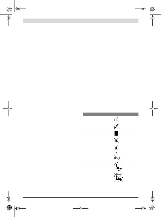
Basic Settings |
|
Tone Signals |
On |
|
|
|
Off |
Display Illumination |
On |
|
|
|
Off |
Auto on/off
Digital vial |
|
|
|
On |
|
|
|
||
|
|
|
Off
Display rotation
On
Off
Bosch Power Tools
OBJ_BUCH-2201-002.book Page 13 Friday, July 22, 2016 9:58 AM
Basic Settings |
|
|
|
Permanent laser beam |
|
|
On |
|
|
||
|
|
|
|
|
|
|
Off |
|
|
|
|
|
|
|
|
|
|
|
|
|
|
|
|
|
|
|
|
Unit of measure, distance |
|
|
m, ft, inch, ... |
(depending on country version) |
|
|
|
Unit of measure, angle |
|
|
°, %, mm/m |
With exception of the “Permanent laser beam” setting, all basic settings are retained when switching off.
Continuous Laser Beam
Do not point the laser beam at persons or animals and do not look into the laser beam yourself, not even from a large distance.
In this setting, the laser beam also remains switched on between measurements; for measuring, it is only required to press the measuring button 2 once.
Measuring Functions
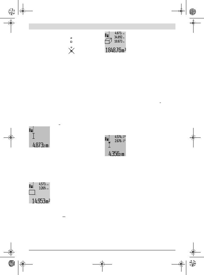
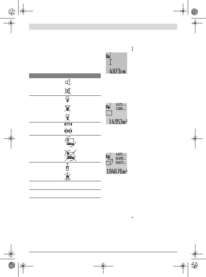
Simple Length Measurement
For length measurements, press button 12 until the “length measurement” indication  appears on the display.
To switch the laser on and for measuring, briefly press the measuring button 2 once each time.
The measured value is displayed in the result line c.
For several subsequent length measurements, the last measured results are displayed in the mea- sured-value lines a.
Area Measurement
For area/surface measurements, press button 12 until the indicator for area measurement appears on the display.
Afterwards, measure the length and the width, one after another, in the same manner as a length measurement. The laser beam remains switched on between both measurements.
Upon completion of the second measurement, the surface is automatically calculated and displayed in the result line c. The individual measured values are displayed in the measured-value lines a.
Volume Measurement
For volume measurements, press button 12 until the indicator for volume measurement appears on the display.
Afterwards, measure the length, width and the height, one after another, in the same manner as for a length measurement. The laser beam remains switched on between all three measurements.
English | 13
Upon completion of the third measurement, the volume is automatically calculated and displayed in the result line c. The individual measured values are displayed in the measured-value lines a.
Values above 1000000 m3 cannot be indicated; “ERROR” appears on the dis-
play. Divide the volume to be measured into individual measurements; their values can then be calculated separately and then summarized.
Continuous Measurement (Tracking) / Minimum/Maxi-
mum Measurement (see figure B)
For continuous measurements, the measuring tool can be moved relative to the target, whereby the measuring value is updated approx. every 0.5 seconds. In this manner, as an example, you can move a certain distance away from a wall, while the actual distance can always be read.
For continuous measurements, press function mode button 8 until the indicator for continuous measurement appears on the display. To start the continuous measurement, press the measuring button 2.
The minimum measurement is used to determine the shortest distance from a fixed reference point. It is used, as an example, for determining plumb lines or horizontal partitions.
The maximum measurement is used to determine the greatest distance from a fixed reference point. It is used, as an example, for determining diagonals.
The current measuring value is displayed in the result line c. The maximum (“max”) and the minimum (“min”) measuring value are displayed in the measured-value lines a. It is always overwritten when the current length measurement value is less than the present minimum or larger than the present maximum value.
The previous minimum and maximum values are deleted by pressing the button for clearing the internal memory 4.
Pressing the measuring button 2 ends the continuous measurement. The last measured value is displayed in the result line c. Pressing the measuring button 2 again restarts a continuous measuring run.
Continuous measurement automatically switches off after
5 min. The last measured value remains indicated in the result line c.
Indirect Distance Measurement
Note: Indirect distance measurement is always less accurate than direct distance measurement. Depending on application, greater measuring errors are possible than with direct distance measurement. To improve the measuring accuracy, we recommend using a tripod (accessory).
The indirect distance measurement is used to measure distances that cannot be measured directly because an obstacle would obstruct the laser beam or no target surface is available as a reflector. This measuring procedure can only be used in vertical direction. Any deviation in horizontal direction leads to measuring errors.
Bosch Power Tools |
1 609 92A 28X | (22.7.16) |
OBJ_BUCH-2201-002.book Page 14 Friday, July 22, 2016 9:58 AM
14 | English
The laser beam remains switched on between the individual measurements.
For indirect length measurements, three measuring modes are available. Each measuring mode can be used for determining different distances.
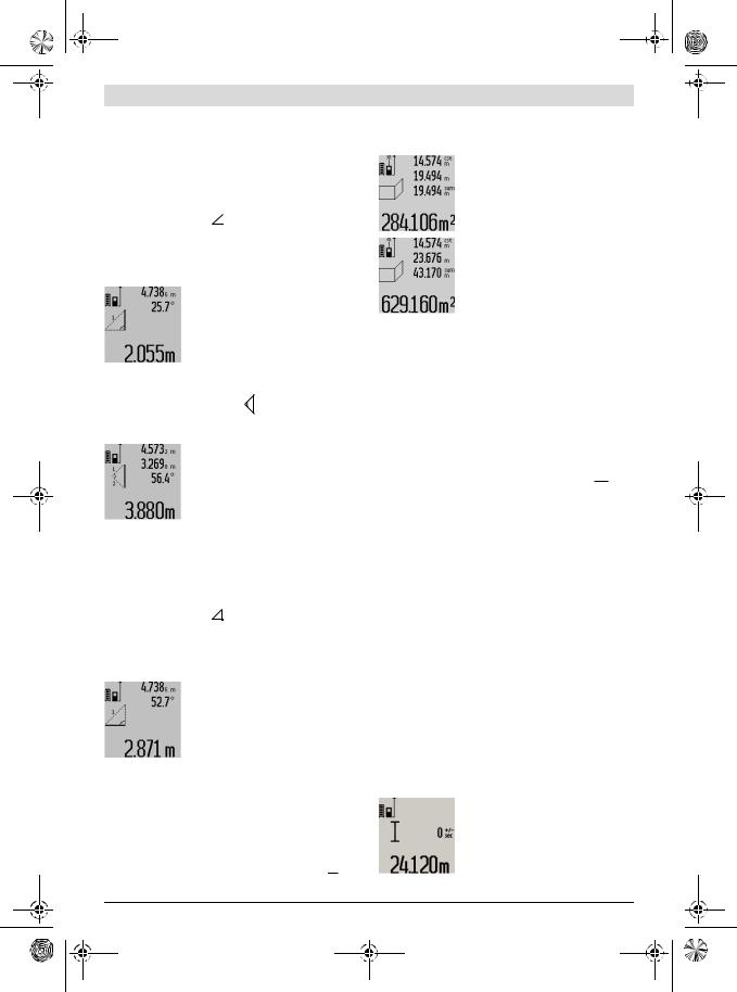
a) Indirect height measurement (see figure C)
Press the function-mode button 8 until the indication for indirect height measurement 1  appears on the display.
Pay attention that the measuring tool is positioned at the same height as the bottom measuring point. Now, tilt the measuring tool around the reference plane and measure distance “1” as for a length measurement.
Upon completion of the measurement, the result for the sought distance “X” is displayed in the result line c. The measuring values for the distance “1” and the angle “α” are displayed in the measured-val- ue lines a.
b) Double indirect height measurement (see figure D)
Press the function-mode button 8 until the indication for double indirect height measurement 1 appears on the display.
2
Measure distances “1” and “2” in this sequence as for a length measurement.
Upon completion of the measurement, the result for the sought distance “X” is displayed in the result line c. The measuring values for the distances “1”, “2” and the angle “α” are displayed in the mea- sured-value lines a.
Pay attention that the reference plane of the measurement (e. g. the rear edge of the measuring tool) remains exactly at the same location for all individual measurements within a measuring sequence.
c) Indirect length measurement (see figure E)
Press the function-mode button 8 until the indication for indirect length measurement 1  appears on the display.
Pay attention that the measuring tool is positioned at the same height as the sought measuring point. Now, tilt the measuring tool around the reference plane and measure distance “1” as for a length measurement.
Upon completion of the measurement, the result for the sought distance “X” is displayed in the result line c. The measuring values for the distance “1” and the angle “α” are displayed in the measured-val- ue lines a.
Wall Surface Measurement (see figure F)
The wall surface measurement is used to determine the sum of several individual surfaces with a common height.
In the example shown, the total surface of several walls that have the same room height A, but different lengths B, are to be determined.
For wall surface measurements, press the function-mode button 8 until the indicator for wall surface measurement  appears on the display.
1 609 92A 28X | (22.7.16)
Measure the room height A as for a length measurement. The measured value (“cst”) is displayed in the top measured-val- ue line a. The laser remains switched on.
Afterwards, measure length B1 of the first wall. The surface is automatically calculated and displayed in the result line c. The length measurement value is displayed in the centre measured-value line a. The laser remains switched on.
Now, measure length B2 of the second wall. The individually measured value displayed in the centre measured-value line a is added to the length B1. The sum of both lengths (“sum”, displayed in the bottom measured-value line a) is multiplied with the stored height A. The total surface value is displayed in the result line c.
In this manner, you can measure any number of further lengths BX, which are automatically added and multiplied with height A.
The condition for a correct area/surface calculation is that the first measured length (in the example the room height A) is identical for all partial surfaces.
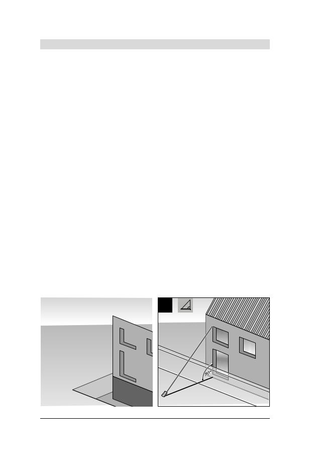
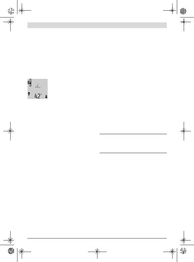
Inclination Measurement (see figure G)
After pressing the grade measurement button 3, the indication for grade measurement appears on the display  . The backside of the measuring tool is used as the reference plane. By pressing the grade measurement button 3 again, the side surfaces of the measuring tool are used as reference plane and the display view is shown turned by 90°.
Press the measuring button 2 to lock the measuring value and accept it in the measured values memory. Pressing the measuring button 2 again continues the measurement.
When the indication flashes during the measuring procedure, then the measuring tool was tilted too much in lateral direction.
If the “digital vial” function is activated in the basic settings, the grade value is also displayed in the other measuring functions in line d of display 1.
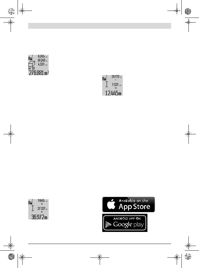
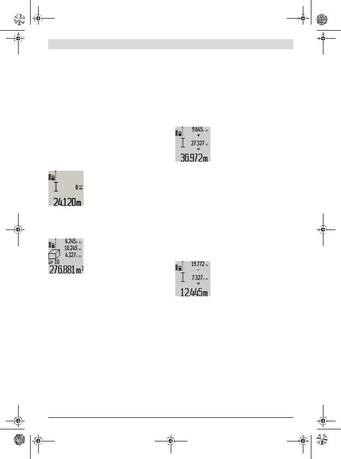
Timer Function
The timer function is helpful when, for example, movements of the measuring tool during measuring are to be prevented.
To activate the timer function, press and hold button 6 until the 
 indicator appears in the display.
The time period from the actuation until the measurement takes place is displayed in the measured-value line a. The time period can be adjusted between 1 s and 60 s by pressing the plus button 11 or the minus button 5.
The measurement takes place automatically after the set time period has elapsed.
The timer function can also be used for distance measurements within other measuring modes (e. g. area/surface
Bosch Power Tools
OBJ_BUCH-2201-002.book Page 15 Friday, July 22, 2016 9:58 AM
measurement). Adding and subtracting measuring results as well as continuous measurements are not possible.
List of the last Measuring Values
The measuring tool stores the last 50 measuring values and their calculations, and displays them in reverse order (last measured value first).
To recall the stored measurements, press button 7. The result of the last measurement is indicated on the display, along with the indicator for the measured-value list e and the memory location of the displayed measurements.
When no further measurements are stored after pressing button 7 again, the measuring tool switches back to the last measuring function. To exit the measured-value list, press one of the measuring-mode buttons.
To continuously save the currently displayed length measurement value as a constant, press and hold the measured-value list button 7 until “CST” is indicated on the display. A mea- sured-value list entry cannot be subsequently saved as a constant.
To use a length measurement value in a measuring mode (e. g. area/surface measurement), press the measured-value list button 7, select the desired entry and confirm by pressing the result button 6.
Deleting Measured Values
Briefly pressing button 4 deletes the last individual measuring value determined in any measuring function. Briefly pressing the button repeatedly deletes the individual measuring values in reverse order.
To delete the currently displayed measured-value list entry, briefly press button 4. To delete the complete measured-val- ue list and the constant “CST”, press and hold the measuredvalue list button 7 and at the same time briefly press button 4.
In wall surface measurement mode, briefly pressing button 4 the first time deletes the last individually measured value; pressing the button a second time deletes all lengths BX, and pressing the button a third time deletes the room height A.
Adding Measured Values
To add measured values, firstly carry out any measurement or select an entry from the measured-value list. Then press the plus button 11. For confirmation, “+” appears on the display. Then carry out a second measurement or select another entry from the measured-value list.
To call up the sum of both measurements, press the result button 6. The calculation is indicated in the measured-value lines a, and the sum in the result line c.
After calculation of the sum, further measured values or measured-value list entries can be added to this result when
pressing the plus button 11 prior to each measurement. Pressing the result button 6 ends the addition.
English | 15
Notes on the addition:
–Mixed length, area and volume values cannot be added together. For example, when a length and area value are added, “ERROR” briefly appears on the display after pressing the result button 6. Afterwards, the measuring tool switches back to the last active measuring mode.
–For each calculation, the result of one measurement is added (e. g. the volume value); for continuous measurements, this would be the displayed measured value in result line c. The addition of individual measured values from the measured-value lines a is not possible.
Subtracting Measured Values
To subtract measuring values, press minus button 5. For confirmation, “– ” is indicated on the display. The further procedure is analog to “Adding Measured Values”.
Data Transmission to other Devices
The measuring tool is equipped with a Bluetooth® module, which enables data transmission via radio technology to certain mobile terminals/devices with a Bluetooth® interface (e. g., smartphones, tablets).
For information on the necessary system requirements for a Bluetooth® connection, please refer to the Bosch website at www.bosch-pt.com
For data transmission via Bluetooth®, time delays between mobile terminal/device and measuring tool may occur. This can be possible due to the distance between both devices or the object being measured.
Data transmission to certain other devices with USB interface is possible via the measuring tool’s micro USB port (e. g. to computers, notebooks). In USB operation, the charging duration n can be significantly prolonged during data transmission.
Activating the Bluetooth® Interface for Data Transmission
to a Mobile Terminal/Device
To activate the Bluetooth® interface, press the measuring tool’s Bluetooth® button 13. Make sure that the Bluetooth® interface on your mobile terminal/device is activated.
Special Bosch applications (apps) are available to extend the functional range of the mobile terminal/device and for simplification of the data processing. Depending on terminal/device, these can be downloaded at the respective app stores:
Bosch Power Tools |
1 609 92A 28X | (22.7.16) |

OBJ_BUCH-2201-002.book Page 16 Friday, July 22, 2016 9:58 AM
16 | English
After starting the Bosch application, the connection between the mobile terminal/device and the measuring tool is established. When several active measuring tools are found, select the appropriate measuring tool. When only one active measuring tool is found, the connection is automatically established.
Note: When establishing the connection between the measuring tool and the mobile terminal/device (e. g., smartphone, tablet) the first time (pairing), the measuring tool’s PIN code may be requested. In this case, enter “0000”.
The connection status and the active connection are indicated on the display 1 (l).
When a connection cannot be established within 5 minutes after pressing the Bluetooth® button 13, the Bluetooth® feature automatically switches off to save the batteries/rechargeable batteries.
When operating the measuring tool in the measuring rail 27, data transmission is not possible.
Deactivating the Bluetooth® Interface
To deactivate the Bluetooth® interface, press the Bluetooth® button 13 or switch the measuring tool off.
When the Bluetooth® interface is deactivated or when the Bluetooth® connection is interrupted (e. g., because of too large distance or obstructions between the measuring tool and the mobile terminal/device as well as electromagnetic disturbances), Bluetooth® (l) is no longer indicated on the display.
Data Transmission via USB Interface
Connect the measuring tool to your computer or notebook with the micro USB cable. After starting the software on your computer or notebook, a connection is established to the measuring tool.
To download the current software and for further information, please refer to the Bosch website at
www.bosch-pt.com
Note: As soon as the measuring tool is connected to a computer or notebook via the micro USB cable, the lithium ion battery is charged. The charge duration varies depending on the charging current.
To recharge the measuring tool as quickly as possible, use the provided charger, see “Battery Charging”.
Working Advice
The measuring tool is equipped with a radio interface. Local operating restrictions, e. g. in airplanes or hospitals, are to be observed.
General Information
The reception lens 17 and the laser beam outlet 18 must not be covered when taking a measurement.
The measuring tool must not be moved while taking a measurement (with the exception of the continuous measurement and grade measurement functions). Therefore, place the measuring tool, as far as this is possible, against or on a firm stop or supporting surface.
Influence Effects on the Measuring Range
The measuring range depends upon the light conditions and the reflection properties of the target surface. For improved visibility of the laser beam when working outdoors and when the sunlight is intense, use the laser viewing glasses 30 (accessory) and the laser target plate 31 (accessory), or shade off the target surface.
Influence Effects on the Measuring Result
Due to physical effects, faulty measurements cannot be excluded when measuring on different surfaces. Included here are:
–Transparent surfaces (e. g., glass, water),
–Reflecting surfaces (e. g., polished metal, glass),
–Porous surfaces (e. g. insulation materials),
–Structured surfaces (e. g., roughcast, natural stone).
If required, use the laser target plate 31 (accessory) on these surfaces.
Furthermore, faulty measurements are also possible when sighting inclined target surfaces.
Also, air layers with varying temperatures or indirectly received reflections can affect the measured value.
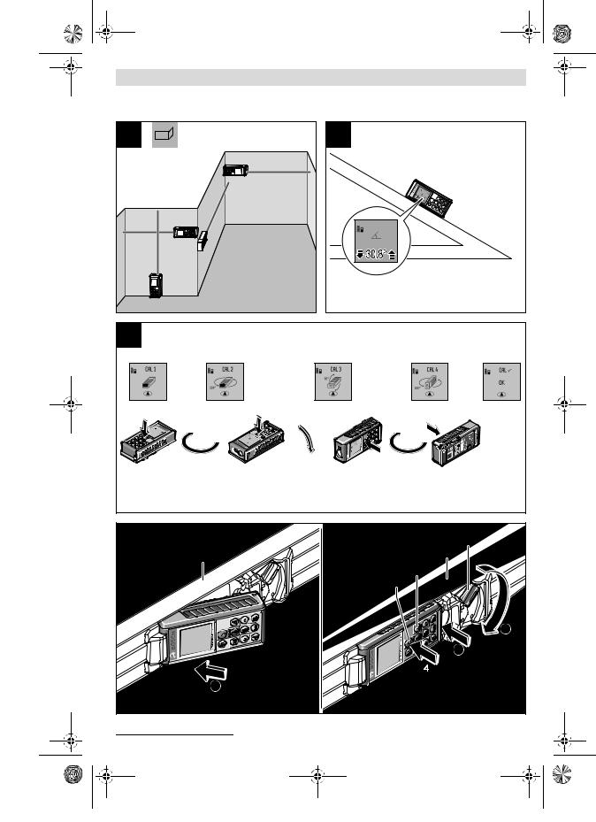
Accuracy Check and Calibration of the Grade Measure-
ment (see figure H)
Regularly check the accuracy of the grade measurement. This is done by carrying out a reversal measurement. For this, place the measuring tool on a table and measure the grade. Turn the measuring tool by 180 ° and measure the grade again. The difference of the indicated reading may not exceed by more than 0.3 ° (max.).
In case of greater deviation, the measuring tool must be recalibrated. For this, press and hold the grade measurement button 3. Follow the directions on the display.
After severe temperature changes and impact, we recommend an accuracy check and, if required, to recalibrate the measuring tool. After a temperature change, the measuring tool must acclimate for a while before calibrating.
Accuracy Check of the Distance Measurement
The accuracy of the distance measurement can be checked as follows:
–Select a permanently unchangeable measuring section with a length of approx. 1 to 10 metres; its length must be precisely known (e. g. the width of a room or a door opening). The measuring distance must be indoors; the target surface for the measurement must be smooth and reflect well.
–Measure the distance 10 times in succession.
The deviation of the individual measurements from the mean value must not exceed ±2 mm (max.). Log the measurements, so that you can compare their accuracy at a later point of time.
1 609 92A 28X | (22.7.16) |
Bosch Power Tools |
OBJ_BUCH-2201-002.book Page 17 Friday, July 22, 2016 9:58 AM
Working with the Tripod (Accessory)
The use of a tripod is particularly necessary for larger distances. Position the measuring tool with the 1/4" thread 19 onto the quick-change plate of the tripod 29 or a commercially available camera tripod. Tighten the measuring tool with the locking screw of the quick-change plate.
Set the corresponding reference level for measurement with a tripod by pushing button 10 (the reference level is the thread).
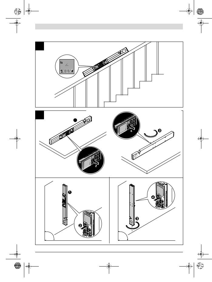
Working with the Measuring Rail (see figures I – K)
The measuring rail 27 can be used for a more accurate grade measurement result. Distance measurements are not possible with the measuring rail.
Place the measuring tool into the measuring rail 27 as shown and lock the measuring tool with locking lever 28. Press the measuring button 2 to activate the “Measuring rail” operating mode.
Regularly check the accuracy of the grade measurement by carrying out a reversal measurement or with the spirit levels of the measuring rail.
In case of greater deviation, the measuring tool must be recalibrated. For this, press and hold the grade measurement button 3. Follow the directions on the display.
When operating the measuring tool in the measuring rail 27, data transmission is not possible.
To end the “Measuring rail” operating mode, switch the measuring tool off and remove it from the measuring rail.
Troubleshooting – Causes and Corrective Measures
Cause |
Corrective Measure |
Temperature warning indicator (k) flashing; measurement not possible
The measuring tool is outside the |
Wait until the measuring |
operating temperature range from |
tool has reached the op- |
– 10 ° C to + 50 °C (in the continuerating temperature |
|
ous measurement function up to |
|
+40 °C). |
|
“ERROR” indication in the display |
|
Addition/Subtraction of measured |
Only add/subtract |
values with different units of mea- |
measured values with |
sure |
the same units of mea- |
|
sure |
The angle between the laser beam |
Enlarge the angle be- |
and the target is too acute. |
tween the laser beam |
|
and the target |
The target surface reflects too in- |
Work with the laser tar- |
tensely (e. g. a mirror) or insuffi- |
get plate 31 (accessory) |
ciently (e. g. black fabric), or the |
|
ambient light is too bright. |
|
|
English | 17 |
|
|
Cause |
Corrective Measure |
The laser beam outlet 18 or the |
Wipe the laser beam out- |
reception lens 17 are misted up |
let 18 and/or the recep- |
(e. g. due to a rapid temperature |
tion lens 17 dry using a |
change). |
soft cloth |
Calculated value is greater than |
Divide calculation into |
1 999 999 or smaller than |
intermediate steps |
– 999 999 m/m2/m3. |
|
Indication “>60 °” or “<– 60 °” on the display |
|
The inclination measuring range |
Carry out the measure- |
for the measuring mode and/or |
ment within the speci- |
the reference plane has been |
fied angle range. |
exceeded. |
|
“CAL” and “ERROR” indication in the display |
|
The calibration of the grade mea- |
Repeat the calibration |
surement was not carried out in |
according to the instruc- |
the correct sequence or in the cortions on the display and
rect positions. |
in the operating instruc- |
|
tions. |
The surfaces used for the calibra- |
Repeat the calibration |
tion were not accurately aligned |
on a horizontal or verti- |
(horizontal or vertical). |
cal surface; if required, |
|
check the surface first |
|
with a level. |
The measuring tool was moved or |
Repeat the calibration |
tilted while pressing the button. |
and hold the measuring |
|
tool in place while press- |
|
ing the button. |
Battery charge-control indicator (g), temperature warning (k) and “ERROR” indication in the display
Temperature of the measuring tool |
Wait until the charge- |
not within the allowable charge- |
temperature range is |
temperature range |
reached. |
Battery charge-control indicator (g) and “ERROR” indication in the display
Battery charging voltage not cor- |
Check if the plug-in con- |
rect |
nection has been estab- |
|
lished correctly and if |
|
the battery charger is |
|
operating properly. |
|
When the unit symbol is |
|
flashing, the battery is |
|
defective and must be |
|
replaced by a Bosch af- |
|
ter-sales service. |
Bluetooth® cannot be activated |
|
The battery is too low. |
Charge the measuring |
|
tool's battery. |
Bosch Power Tools |
1 609 92A 28X | (22.7.16) |
OBJ_BUCH-2201-002.book Page 18 Friday, July 22, 2016 9:58 AM
18 | English
Cause |
Corrective Measure |
No Bluetooth® connection |
|
Failure of the Bluetooth® connection
Check the application on your mobile terminal/device.
Check if Bluetooth® is activated on your measuring tool and mobile terminal/device.
Check your mobile terminal/device for overload.
Reduce the distance between measuring tool and your mobile terminal/device.
Avoid obstructions (e. g., reinforced con-
crete, metal doors) between measuring tool and your mobile terminal/device. Observe clearance to electromagnetic disturbances (e. g., WLAN transmitters).
Data transmission via USB interface not possible
Software error |
Make sure that the soft- |
|
ware runs correctly on |
|
your computer or note- |
|
book. For further infor- |
|
mation, please refer to |
|
the Bosch website at |
|
www.bosch-pt.com |
Micro USB cable |
Check the proper and |
|
tight seating of the micro |
|
USB cable. |
|
Check the micro USB |
|
cable for damage. |
Battery charge-control indicator (g) or prolonged charge duration indication n on the display
Charge duration clearly too long, |
Only use the original |
as charging current too low. |
Bosch charger. |
Measuring result not plausible |
|
The target surface does not reflect |
Cover off the target |
correctly (e. g. water, glass). |
surface |
The laser beam outlet 18 or the re- |
Make sure that the laser |
ception lens 17 are covered. |
beam outlet 18 or the |
|
reception lens 17 are |
|
unobstructed |
Wrong reference level set |
Select reference level |
|
that corresponds to |
|
measurement |
Cause |
Corrective Measure |
Obstruction in path of laser beam |
Laser point must be |
|
completely on target |
|
surface. |
The indication remains unchanged or the measuring tool reacts unexpectedly after pressing a button
Software error |
Press the measuring |
|||
|
|
|
|
button 2 and the button |
|
|
|
|
for clearing the internal |
|
|
|
|
memory / On/Off 4 to re- |
|
|
|
|
set the software. |
|
|
|
|
The measuring tool monitors the correct |
|
|
|
|
|
|
|
|
|
function for each measurement. When a de- |
|
|
|
|
fect is determined, only the symbol shown |
|
|
|
|
|
|
|
|
|
aside flashes in the display. In this case, or |
|
|
|
|
when the above mentioned corrective |
|
|
|
|
measures cannot correct an error, have the |
|
|
|
|
measuring tool checked by an after-sales |
|
|
|
|
service agent for Bosch power tools. |
Maintenance and Service
Maintenance and Cleaning
Store and transport the measuring tool only in the supplied protective pouch.
Keep the measuring tool clean at all times.
Do not immerse the measuring tool in water or other fluids.
Wipe off debris using a moist and soft cloth. Do not use any cleaning agents or solvents.
Maintain the reception lens 17 in particular, with the same care as required for eye glasses or the lens of a camera.
In case of repairs, send in the measuring tool packed in its protective pouch 26.
After-sales Service and Application Service
Our after-sales service responds to your questions concerning maintenance and repair of your product as well as spare parts. Exploded views and information on spare parts can also be found under:
www.bosch-pt.com
Bosch’s application service team will gladly answer questions concerning our products and their accessories.
In all correspondence and spare parts orders, please always include the 10-digit article number given on the nameplate of the product.
1 609 92A 28X | (22.7.16) |
Bosch Power Tools |
OBJ_BUCH-2201-002.book Page 19 Friday, July 22, 2016 9:58 AM
English | 19
People’s Republic of China
China Mainland
Bosch Power Tools (China) Co., Ltd. 567, Bin Kang Road
Bin Jiang District 310052 Hangzhou, P. R. China
Service Hotline: 4008268484 Fax: (0571) 87774502
E-Mail: contact.ptcn@cn.bosch.com www.bosch-pt.com.cn
HK and Macau Special Administrative Regions
Robert Bosch Hong Kong Co. Ltd. 21st Floor, 625 King’s Road North Point, Hong Kong
Customer Service Hotline: +852 2101 0235 Fax: +852 2590 9762
E-Mail: info@hk.bosch.com www.bosch-pt.com.hk
Indonesia
PT Robert Bosch Palma Tower 10th Floor
Jl. RA Kartini II-S Kaveling 6 Sek II Pondok Pinang, Kebayoran Lama Jakarta Selatan 12310 Indonesia
Tel.: (021) 3005 5800
Fax: (021) 3005 5801
E-Mail: boschpowertools@id.bosch.com www.bosch-pt.co.id
Philippines
Robert Bosch, Inc.
28th Floor Fort Legend Towers, 3rd Avenue corner 31st Street, Fort Bonifacio Global City, 1634 Taguig City, Philippines Tel.: (02) 8703871
Fax: (02) 8703870 matheus.contiero@ph.bosch.com www.bosch-pt.com.ph
Bosch Service Center: 9725-27 Kamagong Street San Antonio Village
Makati City, Philippines Tel.: (02) 8999091 Fax: (02) 8976432
E-Mail: rosalie.dagdagan@ph.bosch.com
Malaysia
Robert Bosch Sdn. Bhd. No. 8A, Jalan 13/6 G.P.O. Box 10818 46200 Petaling Jaya Selangor, Malaysia Tel.: (03) 79663194 Fax: (03) 79583838
E-Mail: cheehoe.on@my.bosch.com Toll-Free: 1800 880188 www.bosch-pt.com.my
Thailand
Robert Bosch Ltd. Liberty Square Building No. 287, 11 Floor Silom Road, Bangrak Bangkok 10500
Tel.: 02 6393111
Fax: 02 2384783
Robert Bosch Ltd., P. O. Box 2054 Bangkok 10501, Thailand www.bosch.co.th
Bosch Service – Training Centre
La Salle Tower Ground Floor Unit No.2 10/11 La Salle Moo 16
Srinakharin Road Bangkaew, Bang Plee Samutprakarn 10540 Thailand
Tel.: 02 7587555
Fax: 02 7587525
Singapore
Powerwell Service Centre Ptd Ltd
65 Ubi Crescent, #06-03 Hola Centre Singapore 408559
Tel.: 6746 9770/71 Fax: 6746 9760
E-Mail: powerwellsc@gmail.com Toll-Free: 1800 3338333 www.bosch-pt.com.sg
Vietnam
Robert Bosch Vietnam Co. Ltd 13th Floor , 194 Golden Building 473 Dien Bien Phu Street
Ward 25, Binh Thanh District 84 Ho Chi Minh City
Vietnam
Tel.: (08) 6258 3690
Fax: (08) 6258 3692 Hotline: (08) 6250 8555
E-Mail: tuvankhachhang-pt@vn.bosch.com www.bosch-pt.com.vn www.baohanhbosch-pt.com.vn
Bosch Power Tools |
1 609 92A 28X | (22.7.16) |
OBJ_BUCH-2201-002.book Page 20 Friday, July 22, 2016 9:58 AM
20 |
Australia, New Zealand and Pacific Islands
Robert Bosch Australia Pty. Ltd. Power Tools
Locked Bag 66
Clayton South VIC 3169
Customer Contact Center Inside Australia:
Phone: (01300) 307044 Fax: (01300) 307045 Inside New Zealand: Phone: (0800) 543353 Fax: (0800) 428570 Outside AU and NZ: Phone: +61 3 95415555 www.bosch-pt.com.au www.bosch-pt.co.nz
Supplier code ERAC000385
Egypt
Unimar
20 Markaz kadmat
El tagmoa EL Aoul – New Cairo
Tel: +2 02 224 76091 - 95 / + 2 02 224 78072 - 73 Fax:+2 02 224 78075
E-Mail: adelzaki@unimaregypt.com
Ethiopia
Forever plc
Kebele 2,754, BP 4806, Addis Ababa , Ethiopia
Tel: +251 111 560 600, +251 111 560 600 E-Mail: foreverplc@ethionet.et
Nigeria
C. Woermann Ltd. P.O. Box 318
6, Badejo Kalesanwo Street Matori Industrial Estate Lagos, Nigeria
Tel: +234 17 736 498, +234 17 730 904 E-Mail: d.kornemann@woermann-nigeria.com
Republic of South Africa
Customer service
Hotline: (011) 6519600
Gauteng – BSC Service Centre
35 Roper Street, New Centre Johannesburg
Tel.: (011) 4939375
Fax: (011) 4930126 E-Mail: bsctools@icon.co.za
KZN – BSC Service Centre
Unit E, Almar Centre
143 Crompton Street Pinetown
Tel.: (031) 7012120
Fax: (031) 7012446
E-Mail: bsc.dur@za.bosch.com
1 609 92A 28X | (22.7.16)
Western Cape – BSC Service Centre
Democracy Way, Prosperity Park
Milnerton
Tel.: (021) 5512577
Fax: (021) 5513223
E-Mail: bsc@zsd.co.za
Bosch Headquarters
Midrand, Gauteng
Tel.: (011) 6519600
Fax: (011) 6519880
E-Mail: rbsa-hq.pts@za.bosch.com
Disposal
Measuring tools, accessories and packaging should be sorted for environmental-friendly recycling.
Do not dispose of measuring tools into household waste!
Battery packs/batteries:
Integrated batteries may only be removed for disposal by qualified personnel. Opening the housing shell can damage or destroy the measuring tool.
Completely discharge the battery. Unscrew all screws from the housing and open the housing shell. Disconnect the battery connections and remove the battery.
Do not dispose of battery packs/batteries into household waste, fire or water. Battery packs/batteries should, if possible, be discharged, collected, recycled or disposed of in an environ- mental-friendly manner.
Subject to change without notice.
Radio Frequency Compliance Information (India)
The Laser Range Finder with Bluetooth GLM 100 C Professional has been certified by the Government of India’s WPC (Wireless Planning and Coordination Wing) with Equipment Type Approval Number: ETA-173/2013-RLO (SR).
会影响集成在测量仪中的
明书一起移交。
–
Bosch Power Tools
 OBJ_BUCH-2201-002.book Page 21 Friday, July 22, 2016 9:58 AM
21
上。
并马上将头转出激光光束范围。
激光辐射伤害。
用原厂的备件。
仪。
| 21
®
Bluetooth SIG, Inc. Robert Bosch Power Tools GmbH/
8
1.251


池散发的蒸汽会刺激呼吸道。
®
使用充电器容易酿造火灾。
导致触电。
用者遭受电击的危险。
® ®
请始终打开该页。
Bosch Power Tools |
1 609 92A 28X | (22.7.16) |
OBJ_BUCH-2201-002.book Page 22 Friday, July 22, 2016 9:58 AM
22 |
度。也可以使用本仪器计算面积和体积。本测量仪器 适合在室内和户外执行测量的工作。
® USB
R60 Professional
|
GLM 100 C |
|
|
3 601 K72 7.. |
|
|
|
|
100 A) |
|
0.05–80 B) |
|
45 C) |
|
±1.5 B) |
|
±2.5 C) |
|
0.1 |
|
|
|
0°–360° |
|
(4x90°)D) |
|
|
|
0°–360° |
|
(4x90°)D) |
|
±0.2° E)/G) |
|
0.1° |
|
|
|
–10 °C...+50 °CF) |
|
–20 °C...+50 °C |
|
+5 °C...+40 °C |
|
90 % |
|
2 |
|
635 , <1 |
|
|
|
GLM 100 C |
|||
25 |
|
|
|
|
|
|
|
||
|
|
|
|
|
– 10 |
6 J) |
|||
– 80 |
48 J) |
|||
|
|
|
|
|
– |
±2 / G) |
|||
– |
±10 / G) |
|||
|
|
|
|
|
|
|
|
|
|
– |
20 |
|||
– |
5 |
|||
EPTA-Procedure |
|
|
|
|
01:2014 |
0.14 |
|||
|
51 x 111 x 30 |
|||
|
IP 54 |
|||
|
|
|||
|
|
|
|
|
® |
®4.0 |
|||
|
I) |
|||
Micro USB |
USB 2.0 |
|||
– |
||||
5.0 |
|
|
||
|
||||
– |
500 |
|||
|
|
|||
|
3.7 |
|||
|
1.25 |
|||
|
1 |
|||
|
25000H) |
|||
|
|
|
|
|
|
2 609 120 4.. |
|||
|
3.5 |
|||
- |
5.0 |
|
|
|
|
||||
|
500 |
|||
|
/II |
|||
A) 作用距离就越大。自距离大于80 20
B)100 % 25 °C±0.05 /
C)10 – 100 % –10 °C +50 °C ±0.29 /
D)±60°
E)0° 90° ±0.01°/ 45°
F)40
G)25 °C
H)®
I)® ® SPP
( 20 )
1 609 92A 28X | (22.7.16) |
Bosch Power Tools |
OBJ_BUCH-2201-002.book Page 23 Friday, July 22, 2016 9:58 AM
1
2
3 / **
4 - / - **
5
6 / **
7 / **
8 / **
9
13®
14Micro USB
15Micro USB
191/4"
22QR
25Micro USB
27*, ***
29*
30*
31*
*
***27
a
b "ERROR" c
d / e
f
Bosch Power Tools
| 23
1
1
2
1
g h
i k
l ®
®
®
m
n
®
Bluetooth SIG, Inc. Robert Bosch Power Tools GmbH/
量仪器上的锂离子蓄电池的专用充电器。
牌上规定的电压一致。
率。
g
g
头23 15
1 609 92A 28X | (22.7.16)

OBJ_BUCH-2201-002.book Page 24 Friday, July 22, 2016 9:58 AM
24 |
g g
USBMicro USB USBUSBn
USB
®
""
仪器。
射在仪器上。
视激光的伤害力。
4
5
" " 5
227 " " 25
用固定参考点按键10 "A " 24
2
视激光的伤害力。
2
2
0.5 4
20
" A
" " ",28
/
–4
–2 27
–90 9
–180 9
–19
10
1 609 92A 28X | (22.7.16) |
Bosch Power Tools |
OBJ_BUCH-2201-002.book Page 25 Friday, July 22, 2016 9:58 AM
" "
" "8
8
5 11
" "
2
|
|
|
|
|
|
|
|
|
|
|
|
|
|
|
/ |
|
|
|
|
|
|
|
|
|
|
|
|
|
|
|
|
|
|
|
... |
|
|
|
/ |
" "
视激光的伤害力。
的。您只要轻按一次测量按键2
| 25
12
量按键2
c
一次的测量结果会出现在测量值显 示列a
12
会自动进行运算并将运算所得的面 积显示在测量结果显示列c a
12 ,
,
会自动进行运算并将运算所得的体 积显示在测量结果显示列c a
1000000 m3"ERROR"
/ / B
每0.5
8 2
2
Bosch Power Tools |
1 609 92A 28X | (22.7.16) |

OBJ_BUCH-2201-002.book Page 26 Friday, July 22, 2016 9:58 AM
26 |
c a"max""min"
- 4
2 c2
5 c
式测量。这个测量过程只适用于垂直方向。任何水平 方向的偏差都会导致误测。
能。使用这些功能可以测量不同的距离。
a) C
81 
般测量距离"1"
"X"c "1" "α" a
b) D
8
1 
2
"1" "2"
"X"c "1", "2""α" a
1 609 92A 28X | (22.7.16)
c) E81  "1"
"1"
"X"c "1" "α" a
F
壁的高度A B
8 A ("cst") a
B1 ca
B2a B1"sum" a
A c
BX A
A
G
3 3 90
3 90
Bosch Power Tools
OBJ_BUCH-2201-002.book Page 27 Friday, July 22, 2016 9:58 AM
2 2
侧倾。
" " d1
助计时功能。
6 

a 11 51 60
时。
50
7 e
7
要按住测量值清单按键7 "CST"
按下测量值清单按键76
4
4 "CST"
| 27
7
4
4BX A
11"+"
6 ac
按下增加按键11 6
– 按键6 "ERROR"
– 果显示列c a
5"–"" "
®®
®
www.bosch-pt.com
®
Micro USB USBUSB n
Bosch Power Tools |
1 609 92A 28X | (22.7.16) |
 Loading...