


Greentherm T9800 SEC 199
Table of contents
 Loading...
Bosch Greentherm T9800 SEC 199, Greentherm T9800 SE 160, Greentherm T9800 SE 199 Installation And Operating Instructions Manual

INDOOR RESIDENTIAL AND COMMERCIAL TANKLESS WATER HEATERS
WARNING: If the information in these instructions is not followed
exactly, a fire or explosion may result causing property damage,
personal injury or death.
- Do not store or use gasoline or other flammable vapors and liquids
in the vicinity of this or any other appliance.
- WHAT TO DO IF YOU SMELL GAS
Do not try to light any appliance.
Do not touch any electrical switch; do not
use any phone in your building.
Immediately call your gas supplier from a neighbor’s phone.
Follow the gas supplier’s instructions.
If you cannot reach your gas supplier, call the fire department.
- Installation and service must be performed by a qualified installer,
service agency or the gas supplier.
6720816815-38.1V
Caution!
Improper installation, adjustment, alteration, service or maintenance can cause
in jur y o r pr op ert y d ama ge . Re fe r to th is m an ual . F or a ss ist an ce o r a ddi ti ona l i nf orm at ion
consult a qualified installer, service agency or the gas supplier.
Notice!
Upon completion of the installation, these instructions should be handed to th e user of
the appliance for future reference.
Greentherm T9800 SE 160/199 | SEC 199
160 000/199 000 Btu- Natural Gas | 160 000/199 000 Btu - Liquefied Petroleum (LP) Gas
Installation and Operating Instructions
Temperature Modulated with Electronic Ignition Suitable for heating potable water and space heating
(Intended for variable flow applications, indoor use only)
6 720 816 815 (2018/08) US

2 | Table of contents
Table of contents
1 Key to symbols and safety instructions . . . . . . . . . . 3
1.1 Key to symbols . . . . . . . . . . . . . . . . . . . . . . . 3
1.2 Safety instructions . . . . . . . . . . . . . . . . . . . . 3
2 Safety information . . . . . . . . . . . . . . . . . . . . . . . . . . . 6
3 Appliance details . . . . . . . . . . . . . . . . . . . . . . . . . . . . . 7
3.1 Features . . . . . . . . . . . . . . . . . . . . . . . . . . . . . 7
3.2 Specifications (Technical data) . . . . . . . . . . 8
3.3 Unpacking the heater . . . . . . . . . . . . . . . . . 10
3.4 General rules to follow for safe operation . 11
3.5 Dimensions and minimum installation
clearances . . . . . . . . . . . . . . . . . . . . . . . . . . 12
4 Installation instructions . . . . . . . . . . . . . . . . . . . . . . 13
4.1 Installation tools . . . . . . . . . . . . . . . . . . . . . 13
4.2 Introduction . . . . . . . . . . . . . . . . . . . . . . . . . 13
4.3 Proper location for installing your heater . 13
4.4 Heater placement and clearances . . . . . . . 14
4.5 Hanging appliance on the wall . . . . . . . . . . 14
4.6 Venting . . . . . . . . . . . . . . . . . . . . . . . . . . . . 15
4.7 Factory regulation . . . . . . . . . . . . . . . . . . . . 29
4.8 Gas piping & connections . . . . . . . . . . . . . 30
4.9 Water quality . . . . . . . . . . . . . . . . . . . . . . . . 33
4.10 Water connections . . . . . . . . . . . . . . . . . . . 34
4.11 Domestic hot water recirculation
with external pump . . . . . . . . . . . . . . . . . . . 35
4.12 Space heating applications . . . . . . . . . . . . . 36
4.13 Measuring gas pressure . . . . . . . . . . . . . . . 39
5 Electrical connections . . . . . . . . . . . . . . . . . . . . . . . . 39
5.1 Electrical power supply . . . . . . . . . . . . . . . . 39
5.2 Position of the fuses in control unit . . . . . . 40
7 Maintenance and service . . . . . . . . . . . . . . . . . . . . . 50
7.1 Annual maintenance . . . . . . . . . . . . . . . . . . 50
7.2 Winterizing for seasonal use . . . . . . . . . . . . 50
7.3 Mineral scale build-up . . . . . . . . . . . . . . . . . 51
8 Troubleshooting . . . . . . . . . . . . . . . . . . . . . . . . . . . . . 52
8.1 Introduction . . . . . . . . . . . . . . . . . . . . . . . . . 52
8.2 Burner does not ignite when a hot water
faucet is opened . . . . . . . . . . . . . . . . . . . . . .52
8.3 Water is too hot . . . . . . . . . . . . . . . . . . . . . . 52
8.4 Water is not hot enough . . . . . . . . . . . . . . . 52
8.5 Low water flow/pressure . . . . . . . . . . . . . . 52
8.6 Hot water temperature fluctuates at tap . . 53
8.7 Noisy burner/heater during operation . . . . 53
8.8 Error codes C1, C2, CF and/or CE . . . . . . . 53
8.9 Error codes EA and/or EC . . . . . . . . . . . . . . 53
8.10 Manifold gas pressure . . . . . . . . . . . . . . . . . 54
8.11 Adjusting Gas/Air flow . . . . . . . . . . . . . . . . 54
8.12 CO emissions check . . . . . . . . . . . . . . . . . . 59
9 Problem solving . . . . . . . . . . . . . . . . . . . . . . . . . . . . . 60
9.1 Error code diagnostics . . . . . . . . . . . . . . . . 60
10 Electrical diagram . . . . . . . . . . . . . . . . . . . . . . . . . . . 65
11 Sensor resistance charts . . . . . . . . . . . . . . . . . . . . . 67
12 Interior components diagram . . . . . . . . . . . . . . . . . 68
12.1 Interior components . . . . . . . . . . . . . . . . . . 68
13 Protecting the environment . . . . . . . . . . . . . . . . . . 69
6 Operating Instructions . . . . . . . . . . . . . . . . . . . . . . . 40
6.1 For your safety read before operating
your water heater . . . . . . . . . . . . . . . . . . . . 41
6.2 Power . . . . . . . . . . . . . . . . . . . . . . . . . . . . . . 41
6.3 Error code reset . . . . . . . . . . . . . . . . . . . . . . 41
6.4 Temperature selection . . . . . . . . . . . . . . . . 41
6.5 Information /Adjustments menu . . . . . . . . 43
6.6 Service menu - AU Technical Settings . . . . 46
6.7 Water valves calibration . . . . . . . . . . . . . . . 48
6.8 Gas type . . . . . . . . . . . . . . . . . . . . . . . . . . . . 48
6 720 816 815 (2018/08) Greentherm T9800 SE 160/199 | SEC 199
14 Installer Checklist to be completed by installer
upon installation . . . . . . . . . . . . . . . . . . . . . . . . . . . . .70
Key to symbols and safety instructions | 3
1 Key to symbols and safety instructions
1.1 Key to symbols
Warnings
Warnings in this document are identified by
a warning triangle printed against a grey
background.
Keywords at the start of a warning indicate
the type and seriousness of the ensuing risk
if measures to prevent the risk are not taken.
The following keywords are defined and can be used in this
document:
• DANGER indicates a hazardous situation which, if not
avoided, will result in death or serious injury.
• WARNING indicates a hazardous situation which, if not
avoided, could result in death or serious injury.
• CAUTION indicates a hazardous situation which, if not
avoided, could result in minor to moderate injury.
• NOTICE is used to address practices not related to
personal injury.
Important information
This symbol indicates important information
where there is no risk to people or property.
Additional symbols
Symbol Explanation
▶ Step in an action sequence
Cross-reference to another part of the document
• List entry
– List entry (second level)
Table 1
1.2 Safety instructions
Read all instructions before installing. Perform the steps in the
indicated sequence. Have the water heater inspected by a
trained service technician at least once every year. Failure to
comply with these instructions can result in severe, possibly
fatal, personal injury as well as damage to property and
equipment.
Installation and servicing
▶ Risk of fire when soldering and brazing!
Take appropriate protective measures when soldering and
brazing around combustible and flammable material.
▶ Ensure that only a licensed contractor installs or services
the water heater.
▶ On hot components use only material with adequate
temperature stability.
Installation and commissioning
▶ Do not install this device in rooms with a high moisture level
(e.g. bathrooms, saunas).
Function
▶ To ensure that the water heater functions properly, follow
these installation and maintenance instructions.
▶ Never close the blow-off line of the T&P safety valve. For
safety reasons, water may escape during heating.
If you smell gas
▶ Turn off the gas shut-off valve.
▶ Open windows and doors.
▶ Do not try to light the appliance.
▶ Do not touch any electrical switch, telephone, and do not
use outlets.
▶ Extinguish all open flames. Do not smoke! Do not use
lighters!
▶ Warn all occupants of the building. Do not ring doorbells!
▶ If you can hear gas leaking, leave the building immediately.
▶ Prevent others from entering the building and notify the
police and fire department from outside the building.
▶ From outside the building, call the gas utility company and
a trained and certified installer.
If you smell flue gas
▶ Switch off the appliance.
▶ Open windows and doors.
▶ Inform the certified installer who installed the appliance.
6 720 816 815 (2018/08)Greentherm T9800 SE 160/199 | SEC 199

4 | Key to symbols and safety instructions
Insufficient ventilation may cause toxic flue gas to escape.
Risk of poisoning.
▶ Never close off or reduce the size of the air intake and outlet
openings.
▶ The appliance must not be operated until any obstructions
have been removed.
▶ Inform the customer of the problem and the associated
dangers.
Danger from escaping flue gases
▶ Ensure all vent pipes and chimneys are not damaged or
blocked.
▶ Connect only one appliance to each vent system or
chimney liner, except for cascading installation.
▶ The venting system piping must not feed into another air
extraction duct.
▶ Do not route the flue system piping through or inside
another air extraction duct.
Danger of explosion of flammable gases
▶ Work on gas components may only be carried out by a
trained and certified installer.
▶ Installation, gas and flue connection, initial commissioning,
electrical connections and annual maintenance must only
be carried out by a trained and certified installer.
Combustion air
▶ Keep the combustion air free of corrosive substances
(halogenated hydrocarbons that contain chlorine or
fluorine compounds).
Never shut off safety valves!
▶ Water may escape from the safety valve at any time when
the water is being heated.
Inspection/maintenance
▶ Servicing and repairs may only be carried out by a trained
and certified installer.
▶ Immediately correct all faults to prevent system damage.
▶ Use only Bosch spare parts!
Instruct the customer
▶ Explain to the customer how the appliance works and how
to operate it.
▶ Inform the customer that he/she must not carry out any
alterations or repairs.
Danger from electric shock
▶ Ensure that only an authorized contractor performs
electrical work.
▶ Before performing electrical work, disconnect the power
and secure the unit against unintentional reconnection.
▶ Ensure the system has been disconnected from the power
supply.
Risk of scalding at the hot water fixture
▶ When the water heater is in operation, temperatures in
excess of 120 °F (49 °C) can occur. To limit the
temperature at the tap, install a thermostatic DHW mixing
valve.
▶ Water heated for washing the laundry, dishes and for other
cleaning purposes can cause scalding and permanent
injuries.
▶ Children, disable and elderly are at highest risk of being
scalded. Never leave such individuals in the tub or shower
unattended under any circumstances. Children must not
be allowed to operate hot water faucets themselves.
▶ If the building has occupants in the above groups who
operate hot water faucets, or state laws / local ordinances
stipulate specific water temperatures, take the following
precautions:
– Use the lowest possible temperature setting.
– To prevent scalding, install a tempering device, such as
an automatic mixing valve, at hot water tap or water
heater. Select and install the automatic mixing valve in
accordance with the valve manufacturer's
recommendations and instructions.
▶ Water exiting from drain valves can be extremely hot. To
avoid injuries:
– Check that all connections are tight.
– Direct exiting water away from people.
▶ Measures must be taken to protect against excessive
temperature and pressure! Installation of a T&P safety
valve is required.
To protect against corrosion and ensure compliance with the
rules for electrical safety, observe the following points:
▶ Use metal fittings for potable water heating systems with
plastic piping.
▶ Use only original accessories from the manufacturer.
▶ When installation of the water heater is complete, inspect
and confirm proper ground conductor.
Maintenance
Customers are advised to:
▶ Inspect and maintain the water heater on a yearly basis.
Service as needed. See chapter 7.1.
▶ Use only genuine spare parts.
6 720 816 815 (2018/08) Greentherm T9800 SE 160/199 | SEC 199
Key to symbols and safety instructions | 5
Flooding
▶ After a flood, do not use the appliance if any part has been
submerged. Damage to appliances that have been
submerged can be quite severe and pose numerous safety
risks.
▶ Every appliance that has been submerged must be
replaced.
For your safety
▶ Do not store or use gasoline or other flammable,
combustible or corrosive vapors and liquids in the vicinity
of this or any other appliance.
DANGER: Fatal accidents!
Carbon monoxide poisoning.
▶ Carefully plan where you install the
heater. Correct combustion air supply
and flue pipe installation are very
important. If a gas appliance is not
installed correctly, fatal accidents can
result such as carbon monoxide
poisoning or fire.
DANGER:
Carbon monoxide poisoning.
▶ Exhaust gas must be vented to outside
using approved vent material. See
table 5, page 16 (In Canada use only
ULCS636 approved material). Vent and
combustion air connector piping must
be sealed gas-tight to prevent flue gas
spillage, carbon monoxide emissions
and risk of fire, resulting in severe
personal injury or death. Approved vent
terminations must be used.
DANGER: Electric shock!
Shock hazard: line voltage is present.
▶ Before servicing the water heater,
unplug power supply cord from outlet.
Failure to do so could result in severe
personal injury or death.
WARNING: Damage to the appliance from
over pressure.
▶ The heater must be disconnected from
the gas supply piping system during any
pressure testing of that system at test
pressures equal to or more than 0.5 psi.
NOTICE:
▶ The appliance should be located in an
area where leakage of the heater or
connections will not result in damage to
the area adjacent to the appliance or to
lower floors of the structure. When such
locations cannot be avoided, it is
recommended that a suitable drain pan,
adequately drained, be installed under
the appliance. The pan must not restrict
combustion air flow.
WARNING:
▶ The maximum inlet gas pressure must
not exceed the value specified by the
manufacturer and the minimum value
listed is for the purpose of input
adjustment.
DANGER: Electric shock!
▶ Field wiring connections and electrical
grounding must comply with local
codes, or in the absence of local codes,
with the latest edition of the National
Electric Code, ANSI/NFPA 70, or in
Canada, all electrical wiring must
comply with the local codes and the
Canadian Electrical Code, CSA C22.1
Part 1.
NOTICE:
▶ If a water heater is installed in a closed
water supply system, such as one
having a backflow preventer in the cold
water supply line, means shall be
provided to control thermal expansion.
Contact the water supplier or local
plumbing inspector on how to control
this situation.
6 720 816 815 (2018/08)Greentherm T9800 SE 160/199 | SEC 199
6 | Safety information
WARNING: Fire danger!
▶ Keep appliance area clear and free from
combustible materials, gasoline and
other flammable vapors and liquids.
NOTICE:
▶ Do not obstruct the flow of combustion
and ventilation air.
WARNING: Risk of scalding and property
damage.
▶ Precautions must be taken prior to
manually operating the relief valve to
avoid contact with hot water discharged
from the relief valve and to prevent
water damage.
NOTICE: Appliance damage!
▶Label all wires prior to disconnection
when servicing controls. Wiring errors
can result in improper and dangerous
operation. Verify proper operation after
servicing.
WARNING: System damage!
▶ If a relief valve discharges periodically,
this may be due to thermal expansion in
a closed water supply system. Contact
the water supplier or local plumbing
inspector on how to correct this
situation. Do not plug the relief valve.
WARNING: Personal Injury from toxic
chemicals.
▶ A water heater which will be used to
supply potable water shall not be
connected to any heating system or
component(s) previously used with a
nonpotable water heating appliance.
2 Safety information
WARNING: Personal Injury from toxic
chemicals.
▶ Toxic chemicals, such as those used for
boiler treatment, shall not be introduced
into the potable water used for space
heating.
6 720 816 815 (2018/08) Greentherm T9800 SE 160/199 | SEC 199
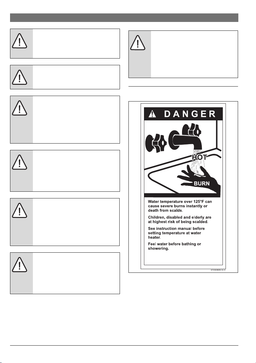
Fig. 1
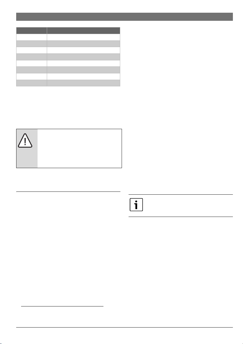
The chart below shows the relationship between water
temperature and time until there is a risk of scalding. It can be
used as the basis for determining the safest water temperature
for your application.
Appliance details | 7
Temperature Time to severe scalding
1)
120 °F (48 °C) longer than 5 minutes
125 °F (51 °C) 1.5 to 2 minutes
130 °F (54 °C) approx. 30 seconds
135 °F (57 °C) approx. 10 seconds
140°F (60°C) less than 5seconds
145 °F (62 °C) less than 3 seconds
150 °F (65 °C) approx. 1.5 seconds
155 °F (68 °C) approx. 1 second
Table 2 Approximate time-temperature relationship until
there is a risk of scalding
1) Source: Moritz, A.R. and Henriques, F.C., Jr. (1947).
Studies of thermal injury. II. The relative importance of
time and surface temperature in the causation of
cutaneous burns, Am J of Pathol, 23, 695-720.
WARNING: This product can expose you to
chemicals including lead, which is known to
the State of California to cause cancer and
birth defects or other reproductive harm. For
more information go to
www.P65Warnings.ca.gov
BOSCH water heater complies with the State of California Lead
Law (AB1953).
High quality materials for long working life
• Copper primary heat exchanger.
• Stainless Steel 316L condensing heat exchanger.
Features
• Compact space saver: mounts on a wall with a supplied
bracket.
• Easily removable one-piece cover.
• On/Off and Temperature touch control buttons.
• Reset function - Long press (> 3 sec.) the ON/OFF button.
•Programmable default temperature.
• Failure codes with message display for easy diagnostics
and repair.
• Real-time diagnostics for troubleshooting/informational
purposes.
• Built in freeze prevention.
• Integrated siphon to limit condensate freezing in external
condensate pipes.
• Available common vent kits, more information at
www.boschheatingandcooling.com.
Accessories (Bosch part #)
• Neutralizer Kit (7738001483)
• Wi-Fi module [802.11 b/g/n (2.4 GHz)]
• Aquastat kit (7736504584)
• External Recirculation Cable (7736504585)
• Tank loading NTC (7736504583)
• Wired remote control (7736504946)
• Wired remote control with WiFi (7736504945)
3 Appliance details
3.1 Features
Residential / Commercial models
• Greentherm T9800 SE residential models
– maximum temperature 120 °F
• Greentherm T9800 SEC commercial models
– maximum temperature 180 °F
Parts
• Color Display with touch controls.
• High power segmented burner with low NOx emissions.
• Modulating gas valve with pressure regulator.
•Modulating water valve.
• Active bypass water valve for quick response to changing
water flows.
•Burner power segmentation with modulation range from
1:22.
1) Can be reprogrammed to achieve 140 °F
1)
BOSCH is constantly improving its products,
therefore specifications are subject to
change without prior notice.
6 720 816 815 (2018/08)Greentherm T9800 SE 160/199 | SEC 199
8 | Appliance details
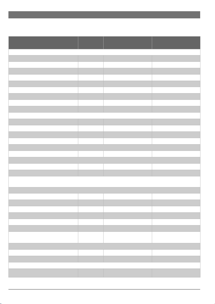
3.2 Specifications (Technical data)
Approved in US/Canada
Technical characteristics Units Greentherm T9800 SE / SEC Greentherm T9800 SE
199 000 Btu 160 000 Btu
Capacity
Maximum flow rate at a 35 °F (19.4 °C) rise1)GPM (l/min) 11.2 (42.4) 9 (34)
Maximum flow rate at a 45 °F (25 °C) rise GPM (l/min) 8.7 (32.9) 7(26.7)
Maximum flow rate at a 55 °F (30.6 °C) rise GPM (l/min) 7.2 (27.5) 5.8 (21.9)
Maximum flow rate at a 75 °F (41.7 °C) rise GPM (l/min) 5.2 (19.7) 4.2 (15.9)
Maximum flow rate at a 90 °F (50 °C) rise GPM (l/min) 4.4 (16.6) 3.5 (13.2)
Maximum output BTU/hr (kW) 197 010 (57.7) 157 608 (46.2)
Maximum input
Thermal efficiency (Efficiency in %) % > 99% > 99%
Minimum Input
Temperature Control
Residential models - Selection range °F ( °C) 100 - 1205) (38 - 49) 100 - 1205) (38 - 49)
Commercial models - Selection range °F ( °C) 100 - 180 (38 - 82) -
Default temperature °F ( °C) 120 (49) 120 (49)
Temperature stability
Gas Requirement
Gas connection inches ¾ " ¾ "
Peak load inlet gas pressure
Propane water column 8" - 13" 8" - 13"
Natural Gas water column 3.5" - 10.5" 3.5" - 10.5"
To assure maximum heat input at maximum vent length minimum gas pressure should be 5" W.C.(199kBtu) and 4" W.C.
(160kBtu). For more information see section 4.6.3.
Water
Top hot water connection NPT inches ¾ " ¾ "
Top cold water connection NPT inches ¾" ¾"
Minimum water flow
Maximum water pressure PSI (bar) 150 (10.3) 150 (10.3)
Minimum recommended water pressure PSI (bar) 18 (1.2) 18 (1.2)
Minimum well pressure PSI (bar) 30 (2.1) 30 (2.1)
Water valve material Polymer (PPS) (Polypropylene
Combustion
CO level ppm 250 (measured) 250 (measured)
CO2 level (set from factory) % see table 25 see table 25
Dimensions
Depth inches (mm) 9 27/32 (250) 9 27/32 (250)
2)
3)
4)
6)
7)
8)
BTU/hr (kW) 199 000 (58.3) 160 000 (46.64)
BTU/hr (kW) 9 000 (2.6) 9 000 (2.6)
°F ( °C) 2 ( 1) 2 ( 1)
GPM (l/min) 0.45 (1.7) 0.45 (1.7)
Polymer (PPS) (Polypropylene
Sulfide)
Sulfide)
Table 3
6 720 816 815 (2018/08) Greentherm T9800 SE 160/199 | SEC 199
Appliance details | 9
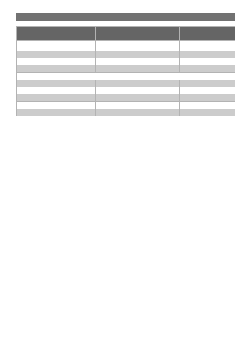
Technical characteristics Units Greentherm T9800 SE / SEC Greentherm T9800 SE
199 000 Btu 160 000 Btu
Width inches (mm) 18
19
/32 (471.5) 18 19/32 (471.5)
Height inches (mm) 31½ (800) 31½ (800)
Net weight pounds (kg) 77.5 (35.2) 73.2 (33.2)
Gross weight pounds (kg) 89.95 (40.8) 85.54 (38.8)
Electrical
Voltage V AC 120 120
Frequency Hz 60 60
Amperage (Idle) mA 40 40
Amperage (operation) A 2,7 2,7
Water protection
9)
IP X4D X4D
Table 3
1) The se f low a re b ased upo n set tin g the uni t to h igh er te mpe ratu res and t hen mixi ng d own u sin g col d wa ter a fte r the uni t, to reach
these flow rates.
2) Input rating is based on sea level operation and need not be changed for operation up to 2000 ft (610 m) elevation. For
operation at elevations above 2000 ft (610 m), input rating is automatically reduced at the rate of 4 percent for each 1000 ft
(305 m) above sea level.
3) When converted to LPG the minimum input is 17 000 BTU/hr (5 kW).
4) With constant flow.
5) Can be reprogrammed to achieve up to 140 °F (60 °C) (see chapter 6.4).
6) Requirements: Steady flows, single unit installations, up to 140 °F (60 °C).
7) To measure Gas Pressure, see Measuring Gas Pressure, chapter 4.13, page 39.
8) Refers to activation point. Deactivation point value is 0.35GPM (1.3 l/min).
9) Protection against water drops.
Safety devices
• Flame failure device (flame detection via ionization rod)
• Overheat prevention
• Inlet water temperature sensor
• Outlet water temperature sensor
• Exhaust flue gas temperature sensor
• Water flow sensor
• Air flow sensing technology (Optiflow)
• Scaling detection sensor (HE flue gas temperature sensor)
6 720 816 815 (2018/08)Greentherm T9800 SE 160/199 | SEC 199
10 | Appliance details
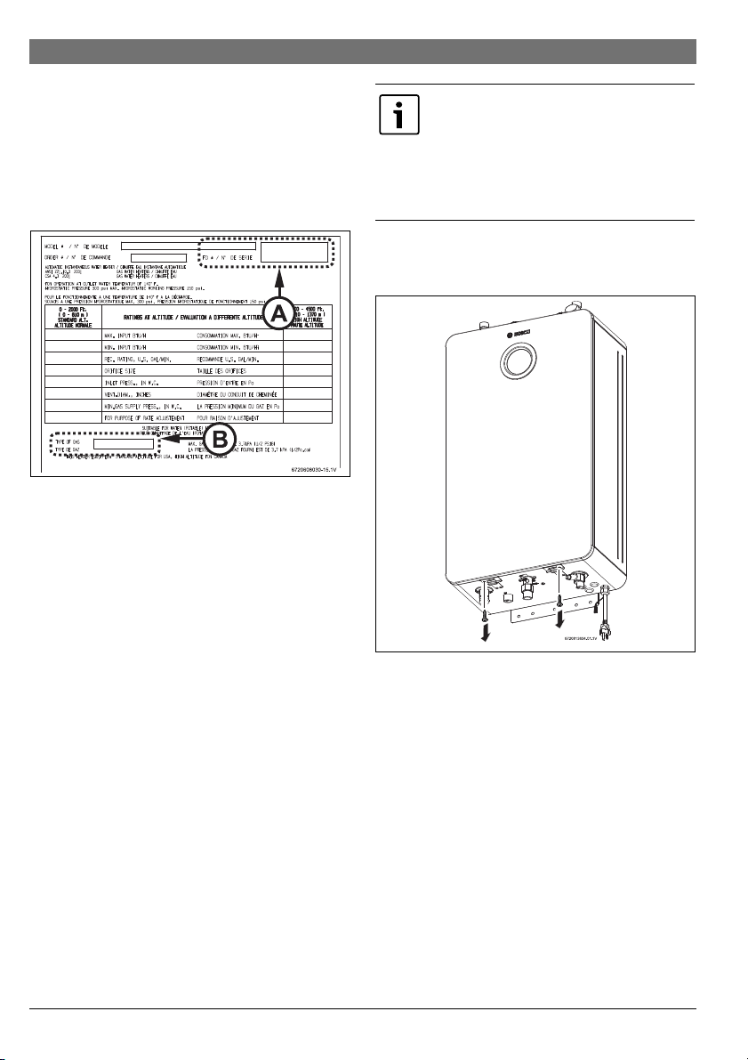
3.3 Unpacking the heater
The heater is default-set by the manufacturer to operate with
Natural Gas, for use with Liquid Propane, follow the conversion
instructions in section 6.8.1. Before commissioning the unit
be certain you have the heater correctly set for your type of
Gas - Propane or Natural Gas. Identification labels are foun d
on the shipping box, and on the rating plate which is located on
the left side (when facing appliance front) of the cover.
Fig. 2 Rating plate
[A] Serial number
[B] Type of gas (Natural gas by default)
3.3.1 The box includes
• Water Heater
•LP Conversion Kit
• Pressure relief valve
• Bracket and screws for wall hanging the heater
• Installation manual (manual can be downloaded at
www.boschheatingandcooling.com)
The Greentherm T9800 SE / SEC are not approved or designed for:
• Manufactured (mobile) homes, boats or any mobile
installation. (Modular homes are acceptable for
installation).
• Use above 8000 ft A.S.L. altitude.
Applications where inlet water temperature is higher than
140°F (60°C) for Residential appliances or 180°F (82°C)
for Commercial appliances.
In these applications a 3 way valve or thermostatic mixing
valve must be installed.
• Booster applications.
▶ Slowly open the front cover [1].
In preheated inlet water applications (i.e.
solar preheat), activation flow rate will vary
depending upon the unit set point, inlet
water temperature and the demand flow rate
thru the unit. Please consult Bosch for
further details to determine if this will
function in your application.
3.3.2 Remove front cover
▶ Loosen two Phillips head screws located on the bottom of
the front cover (fig. 3).
Fig. 3 Loosen two Phillips head screws
6 720 816 815 (2018/08) Greentherm T9800 SE 160/199 | SEC 199
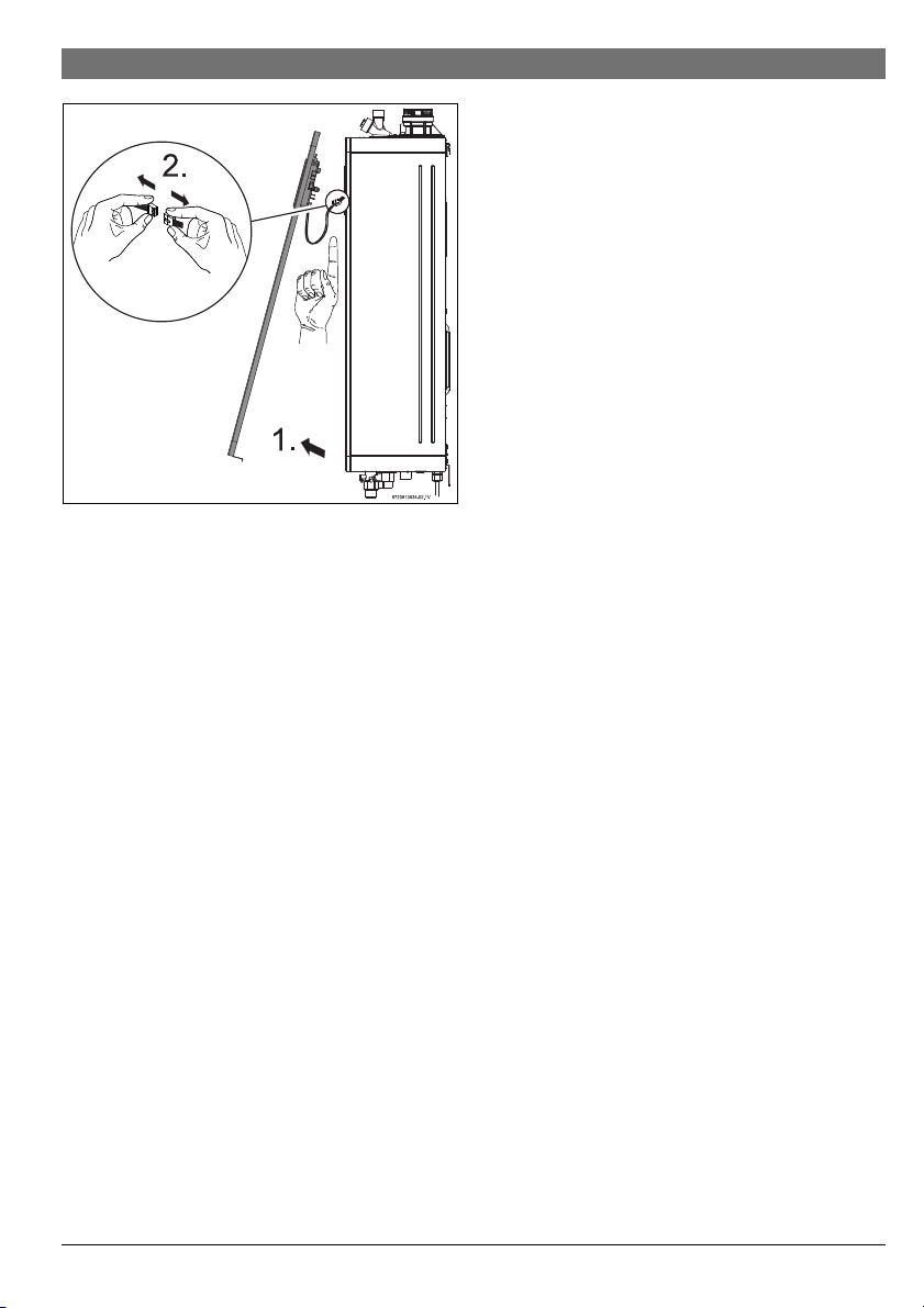
Fig. 4 Open front cover
▶ Disconnect the wire from the HMI (display) [2].
▶ Lift the front cover to remove from the appliance.
▶ Install the appliance so that it hangs vertically.
Appliance details | 11
3.4 General rules to follow for safe operation
1. You must follow these instructions when you install your
heater. In the United States: The installation must conform
with local codes or, in the absence of local codes, the
National Fuel Gas Code ANSI Z223.1/NFPA 54.
In Canada: The Installation must conform with CSA
B149.(1,2) INSTALLATION CODES and /or local
installation codes.
2. Carefully plan where you install the heater. Correct
combustion air supply and vent pipe installation are very
important. If not installed correctly, fatal accidents can
occur, such as carbon monoxide poisoning or fire.
3. When the unit is installed indoors with DIRECT VENT
(exhaust vent and air intake connected to the outside) it is
permitted to be located in bathrooms, bedrooms and
occupied rooms that are normally kept closed. See chapter
4.6 (page 15). If the unit will be installed indoors and use
indoor combustion air (NON-DIRECT VENT), the place
where you install the heater must have enough ventilation.
The National Fuel Gas Codes do not allow NON-DIRECT
VENT gas fired water heater installations in bathrooms,
bedrooms or any occupied rooms normally kept closed.
See chapter 4.6 (page 15).
4. You must correctly vent your heater. See chapter 4.6 (page
15) on VENTING.
5. The appliance and its gas connection must be leak tested
before placing the appliance in operation.
The appliance must be isolated from the gas supply piping
system by closing its individual manual gas shutoff valve
(not supplied with heater) during any pressure testing at
pressures in excess of ½ Psig (3.5 kPa).
6. Keep the water heater area clear and fr ee from
combustibles and flammable liquids. Do not locate the
heater over any material which might burn.
7. Correct gas pressure is critical for the proper operation of
this heater. Gas piping must be sized to provide the
required pressure at the maximum output of the heater,
while all the other gas appliances are in operation. Check
with your local gas supplie r, and see the section on
connecting the gas supply. See chapter 4.8 (page 30).
8. Should overheating occur or the gas supply fail to shut off,
turn off the gas supply at the manual gas shut off valve, on
the gas line. Note: manual gas shutoff valve is not supplied
with the heater but must be field installed.
9. Do not use this appliance if any part has been underwater.
Immediately call the responsible party for the installation of
your appliance to inspect the appliance and to replace any
part of the water heater which has been underwater.
10. Failure to install the heater correctly may lead to unsafe
operation.
6 720 816 815 (2018/08)Greentherm T9800 SE 160/199 | SEC 199
12 | Appliance details
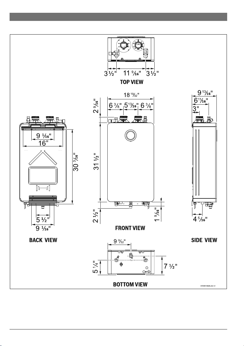
3.5 Dimensions and minimum installation clearances
Fig. 5 Dimensions
6 720 816 815 (2018/08) Greentherm T9800 SE 160/199 | SEC 199

Fig. 6 Side view
Greentherm T9800 SE / SEC
TOP (A) 12"
FRONT (B) 1"
BACK 0"
SIDES 1"
FLOOR (C) 12"
Table 4 Required minimum clearances for combustibles
For servicing access, a 2ft clearance is
recommended to the front cover.
4 Installation instructions
4.1 Installation tools
The following specialized tools may be required if converting
from natural gas to LP:
• Pressure manometer
Installation instructions | 13
4.2 Introduction
Please follow these instructions. Failure to follow
instructions may result in:
▶Damage or injury.
▶Improper operation.
▶Loss of warranty.
DANGER:
▶ The water heater must be installed by a
qualified installer in accordance with
these instructions. If improperly
installed, a hazardous condition such as
explosion or carbon monoxide
poisoning could result. Bosch
Thermotechnology Corp. is not
responsible for improperly installed
appliances.
Common installation practice is to first
determine the path and method of venting,
then design the piping layout.
4.3 Proper location for installing your heater
Carefully select the locati on of the water heater. For your saf ety
and for proper heater operation, you must provide combustion
air to the heater and properly vent the exhaust gases.
Follow the guidelines below:
▶ 1. Locate the heater where venting, gas and plumbing
connections are feasible and convenient.
▶ 2. The hot water lines should be kept short and insulated to
save energy. It is recommended to locate the water heater
as close as practical to the most frequently used hot water
fixtures.
NOTICE: Risk of appliance freezing!
▶ The water in this water heater is cold and
always remains cold except for the times
the burner is on. In the event of power
outage in conjunction with freezing
temperatures, the heater should be
drained.
See chapter 7.2, page 50 “Winterizing”
for draining instructions.
6 720 816 815 (2018/08)Greentherm T9800 SE 160/199 | SEC 199
14 | Installation instructions
WARNING:
▶ Flammable materials, gasoline,
pressurized containers, or any other
items or articles that are potential fire
hazards must NOT be placed on or
adjacent to the heater. The appliance
area must be kept free of all combustible
materials, gasoline and other flammable
vapors and liquids.
4.4 Heater placement and clearances
The water heater design is approved for installation on a
combustible wall (see chapter 4.5 Mounting installation)
provided the floor covering below the heater is
noncombustible.
For installations in an alcove or closet, maintain the minimum
clearances to combustible and non-combustible materials. See
fig. 6, page 13.
4.5 Hanging appliance on the wall
WARNING: Severe personal injury and
property damage!
Before mounting appliance:
▶ Check that there are no loose or
damaged parts inside the appliance.
▶ Set the heater gas type according to the
gas supplied to the unit.
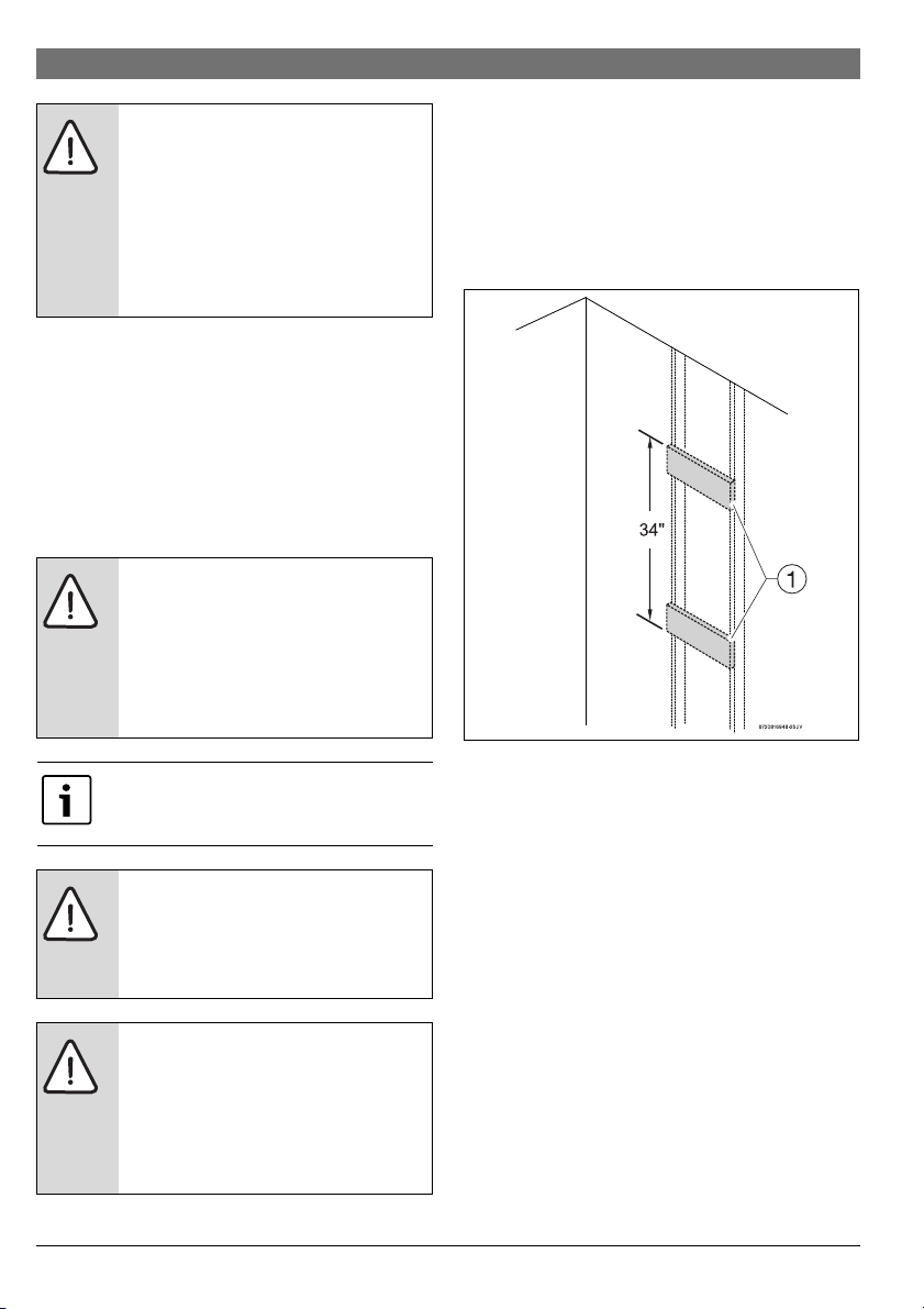
If the wall is sheathed with plaster or drywall, it is
recommended that two support boards, either 1"x 4" or 1/2"
(minimum) plywood first be attached across a pair of studs,
see fig. 7.
▶ Secure the wall mounting bracket pr ovided with the heater
to a wall surface. The heater must be kept level on the wall
surface, see fig. 8, page 15.
▶ Hang the appliance on the bracket, see fig. 9.
Fig. 7 Distance between support boards
Front cover should be removed (see
instructions on page 10) in order to inspect
components visually.
WARNING:
▶ Do not install this appliance on a
carpeted wall. The heater must be
mounted on a wall using appropriate
anchoring materials.
NOTICE: Risk of appliance freezing!
▶ In areas where outside temperature is
routinely below 32°F (0 °C) and the
heater is to be installed on the inside of
an exterior wall, provide a minimum 2"
air gap or rigid insulation between the
heater back and the wall.
6 720 816 815 (2018/08) Greentherm T9800 SE 160/199 | SEC 199
[1] Support boards
Vertical studs are typically 16" (406mm) on center.
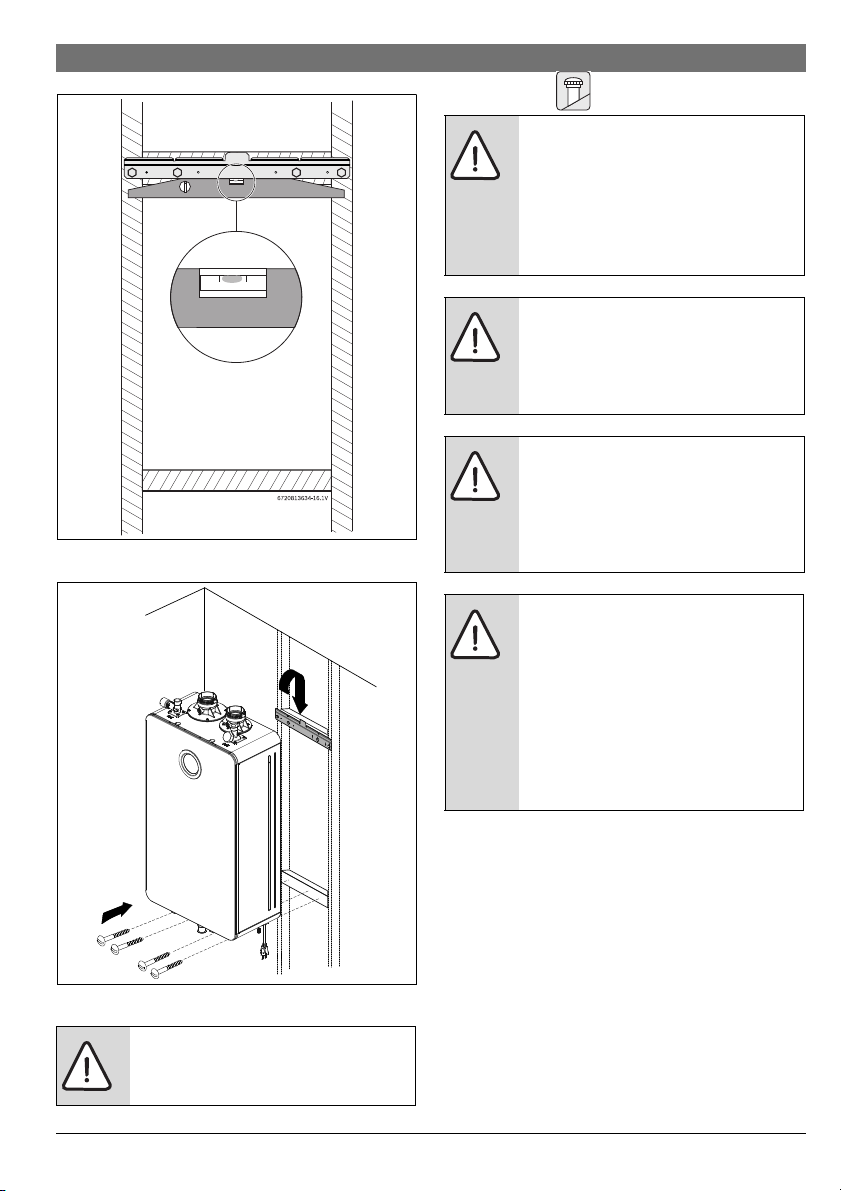
Fig. 8 Leveling wall mounting bracket
6720813634-28.1V
1.
2.
Installation instructions | 15
4.6 Venting
DANGER:
▶ Do not reduce the exhaust or
combustion air vent pipe sizes.
▶ Do not common vent with any other
vented appliance or stove.
▶ Do not use Type-B vent as the actual
exhaust vent system for the appliance.
DANGER: Flue gas poisoning!
▶ Failure to vent the exhaust gases to the
outside (see table 5 for proper material)
may result in dangerous flue gases filling
the structure in which it is installed.
NOTICE:
▶ Installations resulting in negative
pressure/back draft require sealed
combustion (twin pipe / concentric).
Damage caused from back draft, ie.
freezing, is not covered by warranty.
NOTICE: Appliance malfunction!
▶ Protect the exhaust and inlet from
leaves and debris by installing a screen
on the end of the termination. ¼ " mesh
minimum opening is recommended on
screen.
▶ Do not install the water heater in areas
where dust and chemicals like hair
sprays, spray detergents, chlorine, may
accumulate.
Fig. 9 Mounting the heater
CAUTION: Personal injury and property
damage.
▶ Appliance must be installed vertically.
6 720 816 815 (2018/08)Greentherm T9800 SE 160/199 | SEC 199
16 | Installation instructions
Flue temperature:
▶ To prevent the risk of flue material
overheat the appliance's flue
temperature is sensed and is limited.
The flue temperature limit is depending
on inlet water temperature.
▶ Residential models: Maximum flue
temperature is limited to 145 °F.
▶ Commercial models: Maximum flue
temperature is limited to 145 °F with
water temperature set points up to
140 °F. When water recirculation mode
is activated and temperature set point is
above 140 °F, maximum flue
temperature is limited to 194 °F. For flue
temperature above 145 °F the use of
PVC flue material is not allowed.
4.6.1 Vent options
This appliance can be installed as direct vent or Category IV.
The Greentherm T9800 SE / SEC is approved with the
following venting options:
Item Material United States Canada
Vent or air intake pipe
and fitting
PP flexible M&G / Duravent
concentric
Centrotherm
rigid
PVC schedule 40 ANSI/ASTM D1785
PVC-DWV ANSI/ASTM D2665
Thermoplastic vent pipe
must be certified to ULC
S636.
Air Intake pipe may be of any
material listed (left)
CPVC schedule 40 ANSI/ASTM F441
ABS-DWV schedule 40 ANSI/ASTM D2661
Pipe cement / primer PVC ANSI/ASTM D2564
CPVC ANSI/ASTM F493
ABS ANSI/ASTM D2235
Table 5 Approved vent materials
For specific questions concerning vent material,
specifications, usage or installation, please contact the
Do not use cellular foam core pipe for
exhaust. Approved for intake only.
vent manufacturer directly.
Approved Vent Manufacturers;
•M&G
•Centrotherm
•IPEX
•Royal Plastics
•Eccovent
•Charlotte
•Z-Flex
The vent connection for the appliance is secured with a clamp
on the appliance exhaust adapter. All other vent connections
must be glued, except PP and flex PP. Slide the vent pipe into
the exhaust adapter. The exhaust pipe must be properly
supported and must be pitched a minimum of a ¼ inch per foot
back to the appliance. This allows the condensate to drain
properly.
Maximum vent lengths and equivalent lengths per table 8
apply.
6 720 816 815 (2018/08) Greentherm T9800 SE 160/199 | SEC 199
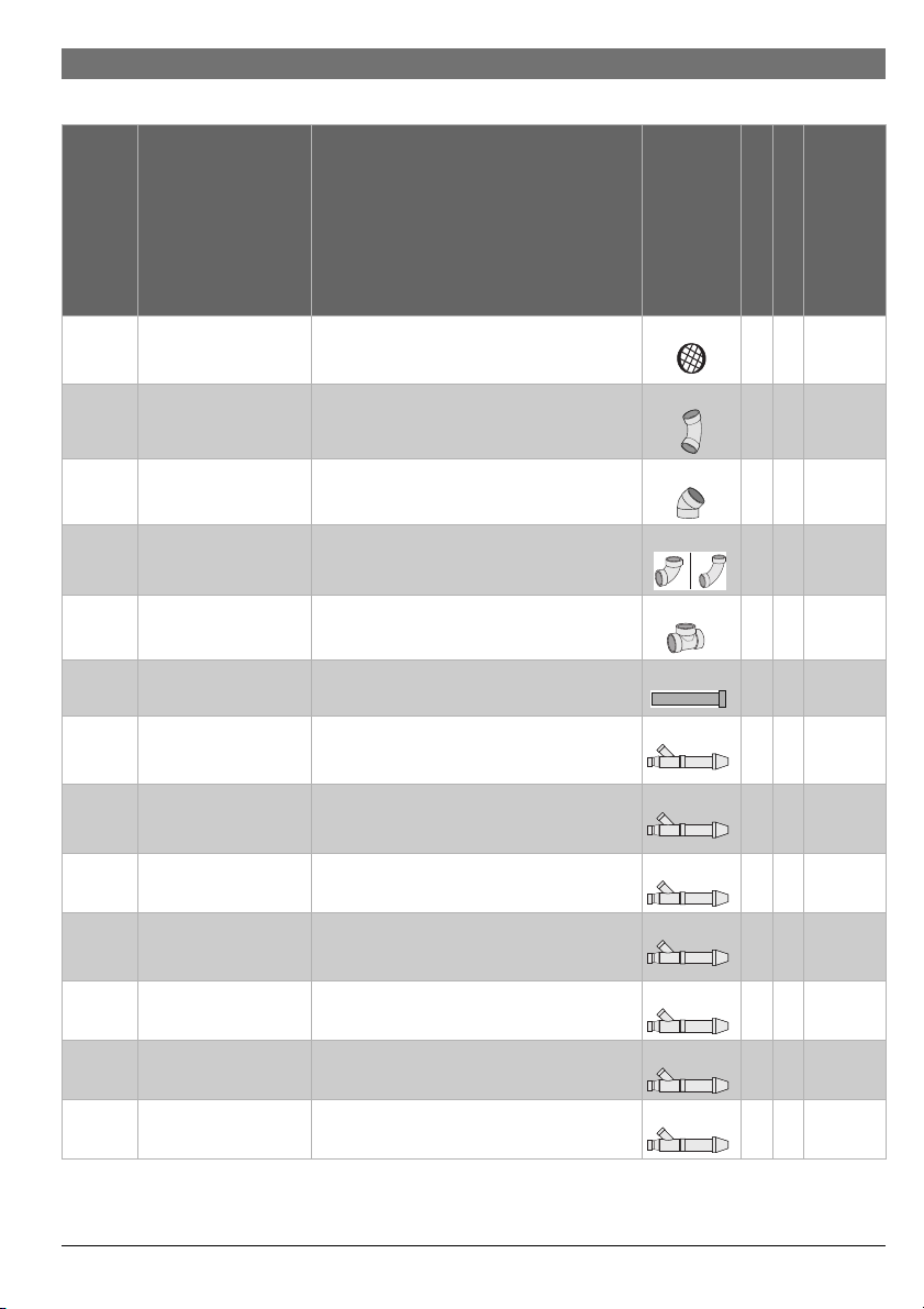
4.6.2 Approved vent components and terminations
Installation instructions | 17
Vertical
Horizontal
Equivalent Lengths (Ft.)
hh 2
h h 2.5
Product description
Manufacturer
Bosch 196050
Manufacturer part number
196051
196052
2" Bird screen
3" Bird screen
4" Bird screen
- - 2", 3", and 4" SCH40 (Solid Core) PVC/CPVC
Diagram
45° long sweep elbow
- - 2", 3", and 4" SCH40 (Solid Core) PVC/CPVC
hh 2.5
45° short sweep elbow
- - 2", 3", and 4" SCH40 (Solid Core) PVC/CPVC
90 ° short/long/extra long, sweep elbow
1)
- - 2", 3", and 4" SCH 40 (Solid Core) PVC/CPVC
h h 5
hh 10
"T" terminal w/vent screen
- - 2", 3" and 4" SCH40 (Solid Core) PVC/CPVC
h h 1
straight pipe
IPEX 196005 PVC Concentric termination (2" by 16" long) hh Exhaust:
1.5
Intake: 20
IPEX 196105 PVC Concentric termination (2" by 28" long) h h Exhaust:
2.5
Intake: 20
IPEX 196125 PVC Concentric Termination Kit (2" by 40" long) hhExhaust: 3
Intake: 20
IPEX 196006 / 197009 PVC / CPVC Concentric Termination Kit
(3" by 20" long)
IPEX 196106 / 197107 PVC / CPVC Concentric Termination Kit
(3" by 32" long)
IPEX 196116 / 197117 PVC / CPVC Concentric Termination Kit
(3" by 34" long)
IPEX 196021 / 197021 PVC / CPVC Concentric Termination Kit
(4" by 36" long)
Table 6 Approved PVC/CPVC Vent Components & Terminations
h h Exhaust:
1.5
Intake: 40
hhExhaust: 2
Intake: 40
h h Exhaust: 2
Intake: 40
hhExhaust: 2
Intake: 60
6 720 816 815 (2018/08)Greentherm T9800 SE 160/199 | SEC 199
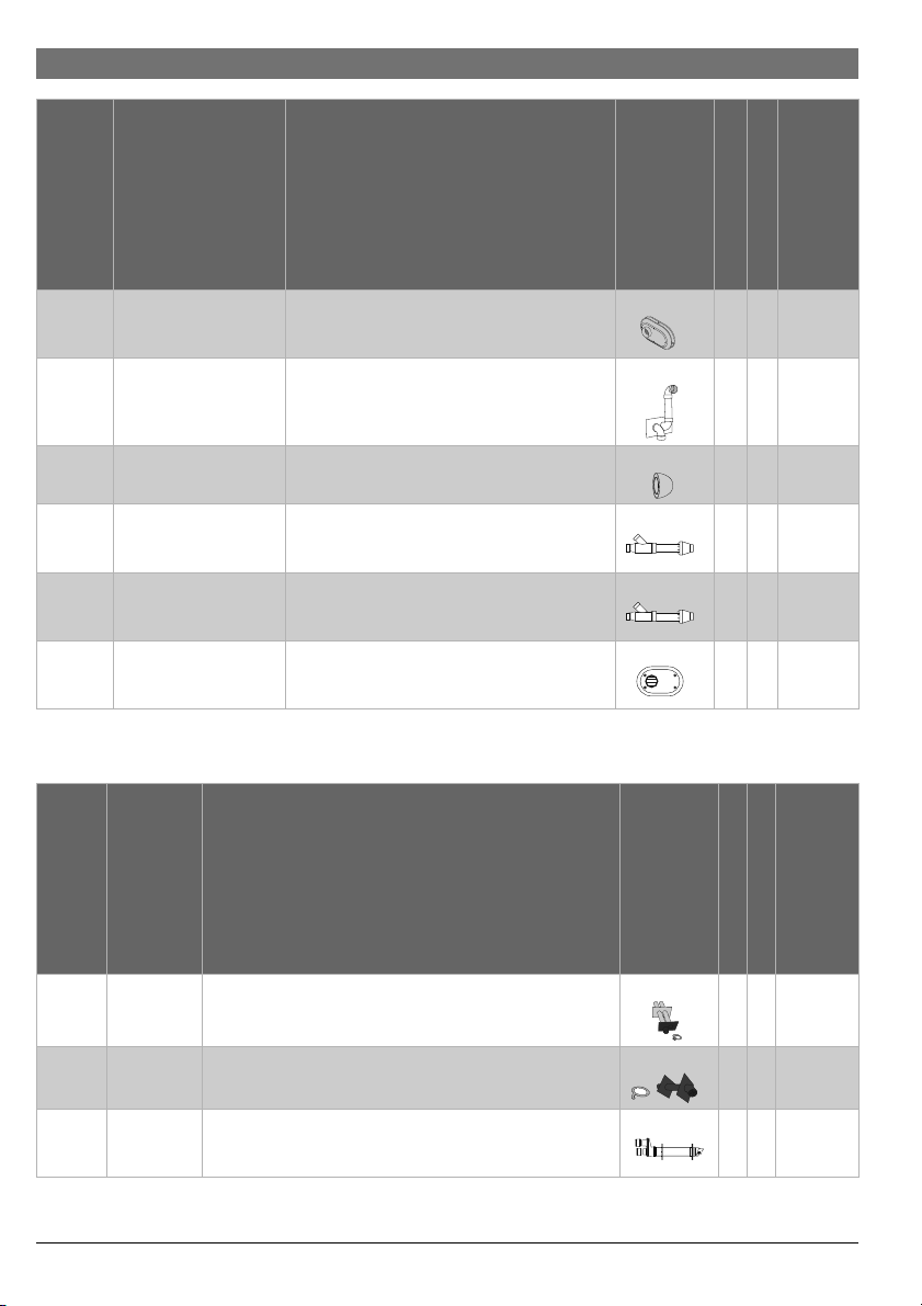
18 | Installation instructions
Product description
Manufacturer
IPEX 196984
IPEX 081216
Temple
industries
Royal
Manufacturer part number
2" PVC Low profile termination kit
196985
196986
3" PVC Low profile termination kit
4" PVC Low profile termination kit
2" PVC Wall Termination Kit
081219
3" PVC Wall Termination Kit
ECAP 321 2" PVC termination E-Cap
3" PVC termination E-Cap
52CVKGVS6502 2" GVS-65 Concentric Vent Termination Kit hhExhaust: 2
Plumbing
Solutions
Royal
52CVKGVS6503 3" GVS-65 Concentric Vent Termination Kit h h Exhaust: 2
Plumbing
Solutions
Royal
Plumbing
52SWVKGVS6502
52SWVKGVS6503
2" GVS-65 Side Wall Vent Termination Kit
3" GVS-65 Side Wall Vent Termination Kit
Solutions
Table 6 Approved PVC/CPVC Vent Components & Terminations
1) Close sweep fittings are not accepted.
Diagram
Horizontal
Vertical
Equivalent Lengths (Ft.)
h Exhaust: 0
Intake: 5
h Exhaust:
15
Intake: 7.5
h 2
4
Intake: 20
Intake: 40
h Exhaust: 0
Intake: 5
Vertical
Horizontal
Equivalent Lengths (Ft.)
h Exhaust: 2
Intake: 2
h 6
h Exhaust:
20
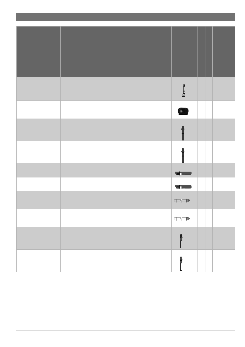
Manufacturer
Duravent
M&G
Duravent
M&G
Duravent
M&G
Manufacturer part number
810009685
810009713
810009745
810009684
810009712
810009682
810009710
Diagram
Product description
2" PP Twin pipe termination
3" PP Twin pipe termination
4" PP Twin pipe termination
2" PP Single Horizontal Termination
3" PP Single Horizontal Termination
(2" x 4") PP Horizontal Termination Kit - Concentric
(3" x 5") PP Horizontal Termination Kit - Concentric
Intake: 40
Table 7 Approved PP Vent Components & Terminations
6 720 816 815 (2018/08) Greentherm T9800 SE 160/199 | SEC 199
Installation instructions | 19
Manufacturer
Duravent
M&G
Centrotherm
Centrotherm
Centrotherm
Centrotherm
Centrotherm
Ecco
Manufacturing
Ecco
Manufacturing
Ecco
Manufact
uring
Vertical
Horizontal
Equivalent Lengths (Ft.)
h Exhaust:
20
Intake: 40
h Exhaust: 0
Intake: 5
Product description
Manufacturer part number
810009692
810009720
810009693
810009721
(2" x 4") Black PP Vertical Termination Kit - Concentric
(3" x 5") Black PP Vertical Termination Kit - Concentric
(2" x 4") Terra-Cotta PP Vertical Termination Kit - Concentric
(3" x 5") Terra-Cotta PP Vertical Termination Kit - Concentric
ISLPT0202
ISLPT0303
Diagram
2" Low profile Wall Termination
3" Low profile Wall Termination
ICRT2439 2" x 4" Concentric Roof Termination h Exhaust: 5
Intake: 5
ICRT3539 3" x 5" Concentric Roof Termination h Exhaust:
10
Intake: 10
ICWT242 2" x 4" Concentric Wall Termination h Exhaust: 4
Intake: 4
ICWT352 3" x 5" Concentric Wall Termination h Exhaust: 6
Intake: 6
190288 2" PP Concentric Terminations Horizontal (Wall) Terminations h Exhaust: 4
Intake: 4
190388 3" PP Concentric Terminations Horizontal (Wall) Terminations h Exhaust: 6
Intake: 6
190295 2" PP Vertical (Roof) Terminations h Exhaust: 4
Intake: 4
Ecco
190395 3" PP Vertical (Roof) Terminations h Exhaust: 8
Manufact
uring
Table 7 Approved PP Vent Components & Terminations
Intake: 8
6 720 816 815 (2018/08)Greentherm T9800 SE 160/199 | SEC 199
20 | Installation instructions
4.6.3 Vent specifications
Establish vent clearances that comply with the vent
manufacturer's specifications and all applicable national/local
codes.
Minimum combustion air and exhaust pipe length
The min imum exh aust pip e len gth is 1 f t (0 .3m) of s tra ight ven t
pipe. The minimum air intake pipe length is 1 ft or one 90°
elbow or an air intake grill cap to prevent debris from falling into
the appliance.
Maximum combustion air and exhaust pipe length
The table 8 displays the maximum allowable straight pipe
lengths for air intake and exhaust piping. Reduce the maximum
allowable pipe length by the equivalent lengths for each elbow
used and termination used.
PROPER GAS PRESSURE!
The following section assumes the water
heater will receive gas pressure greater than
or equal to 5" WC for the 199kBTU models
(4" WC for 160kBTU models). In cases of gas
pressure below 5" WC for the 199kBTU (4"
WC for the 160kBTU models) the maximum
heat input is reduced.
The values of maximum flue length in
table 8 are before any deductions for
elbows or terminations.
The vent for this appliance shall not terminate:
1. over public walkways; or
2. near soffit vents or crawl space vents or other areas where
condensate or vapor could create a nuisance or hazard or
cause papery damage; or
3. where condensate vapor could cause damage or could be
detrimental to the operation of regulators, relief valves, or
other equipment.
Venting Max equivalent
Exhaust length
2" Twin pipe 60ft
3" Twin pipe 280 ft
1)
1)
2"/ 4"
Max equivalent
Intake length
1)
60ft
60ft
280ft
Concentric pipe
3"/ 5"
280ft
1)
Concentric pipe
Table 8 Maximum Allowable Exhaust and Air Intake Lengths
1) To assure maximum heat input at maximum vent length
minimum gas pressure should be 5" W.C. for the 199 kBTU
models and 4" W.C. for the 160 kBTU models.
Improper gas pressure or vent length may
result in undesired symptoms or errors such
as noisy burner, C1, C2, CF.
6 720 816 815 (2018/08) Greentherm T9800 SE 160/199 | SEC 199
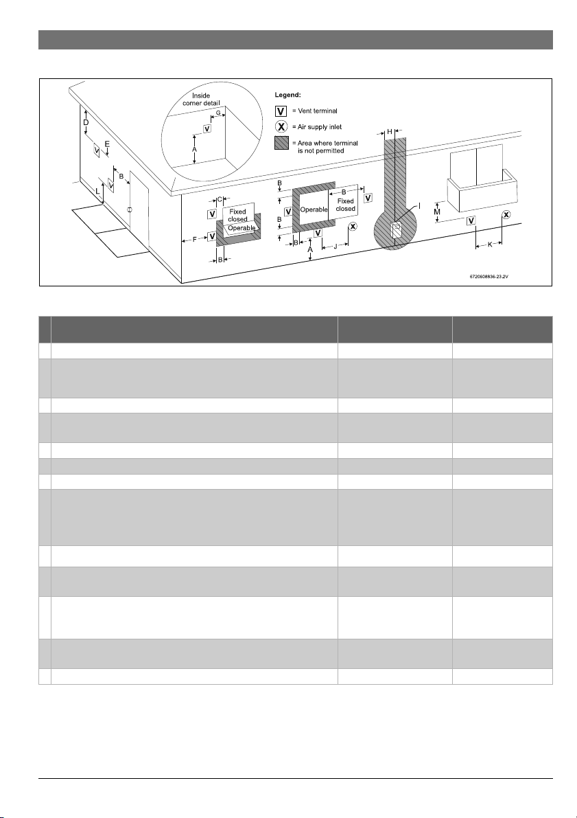
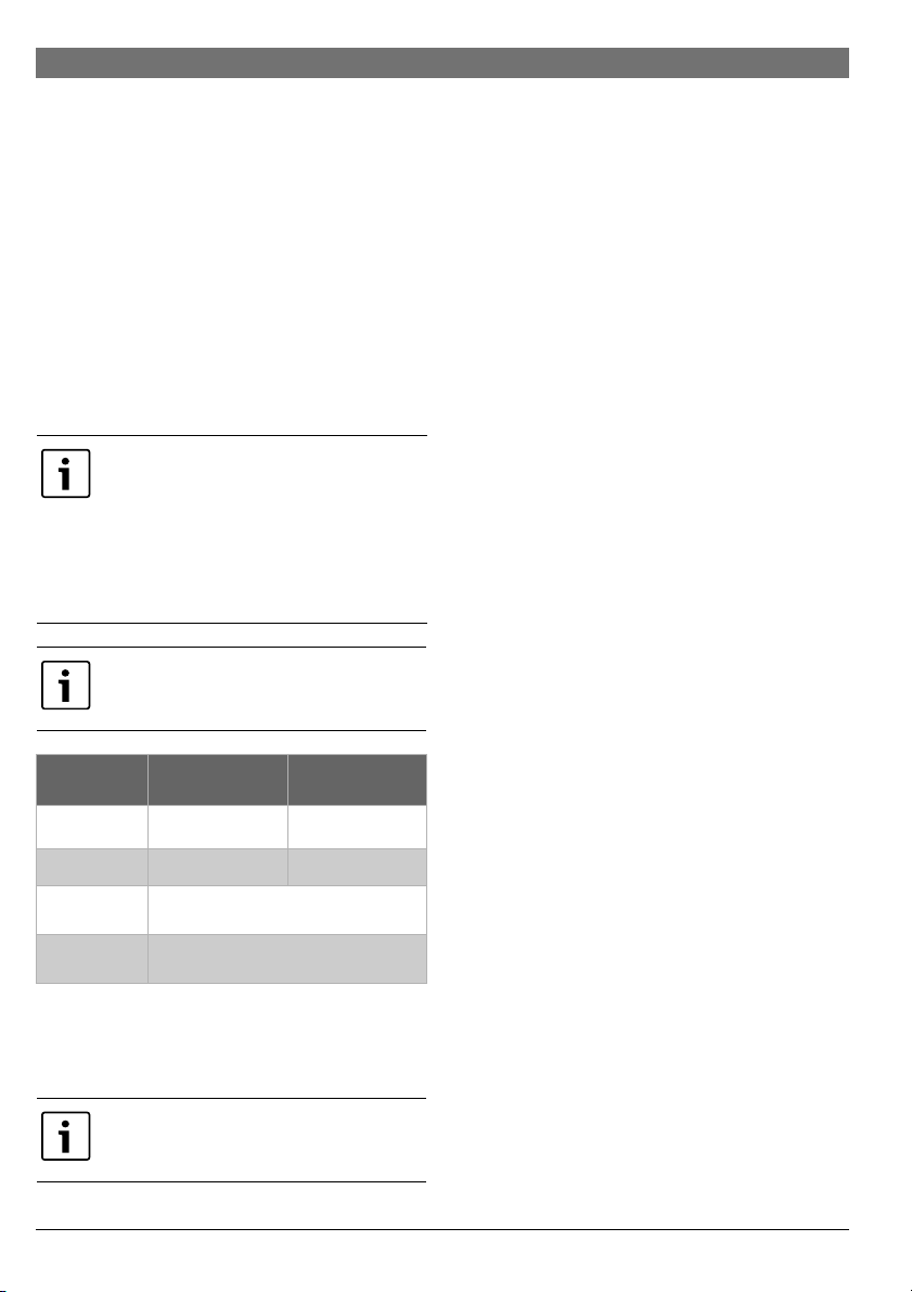
Required direct vent terminal clearances (twin pipe / concentric penetration)
Fig. 10
Installation instructions | 21
Canadian installations1)
with direct vent terminals
U.S. installations2)
with direct vent
A Clearance above grade, veranda, porch, deck or balcony 12 in. (30cm) 12 in. (30cm)
B Clearance to window or door that may be opened 36 in. (91cm) 12 in. (30cm) below or
to side of opening; 12
in. (30cm) above
C Clearance to permanently closed window * *
D Vertical clearance to ventilated soffit located above the terminal within
* *
a horizontal distance of 2 ft (61cm) from the center line of the terminal.
E Clearance to unventilated soffit * *
F Clearance to outside corner * *
G Clearance to inside corner * *
H Clearance to each side of center line extended above meter/regulator
assembly
36 in. (91cm) within a
height 15 ft (4.6m) above
*
the meter/ regulator
assembly
I Clearance to service regulator vent outlet 36 in. (91cm) *
J Clearance to nonmechanical air supply inlet to building or the
36 in. (91cm) 12 in. (30cm)
combustion air inlet to any other appliance.
K Clearance to a mechanical air supply inlet 6 feet (1.83m) 36 in. (91cm) above if
within 10 ft (3m)
horizontally
L Clearance above paved sidewalk or paved driveway located on public
7 ft (2.13m)
3)
*
property
M Clearance under veranda, porch deck or balcony 12 in. (30cm)
4)
*
Table 9
1) In accordance with the current CSA B149.1 Natural Gas and Propane Installation Code.
2) In accordance with the current ANSI Z223.1 / NFPA 54, National Fuel Gas Code.
6 720 816 815 (2018/08)Greentherm T9800 SE 160/199 | SEC 199

22 | Installation instructions
3) A vent shall not terminate directly above a sidewalk or paved driveway that is located between two single family dwellings and
serves both dwellings.
4) Permitted only if veranda, porch, deck or balcony is fully open on a minimum of two sides beneath the floor.
[*] For clearances not specified in ANSI Z223.1 / NFPA 54 or CSA-B149.1, one of the following shall be indicated:
a) a minimum clearance value determined by testing in accordance with Clause 5.20, Draft hoods, or;
b) a reference to the following footnote:
“Clearance in accordance with local installation codes and the requirements of the gas supplier.”
6 720 816 815 (2018/08) Greentherm T9800 SE 160/199 | SEC 199
Loading...