

Page 1
THE APPLIANCE IS FOR USE WITH
NATURAL GAS OR L.P.G. (Cat II 2H3P TYPE C13 & C33)
NATURAL GAS:
WORCESTER GREENSTAR 24i junior GC NUMBER 47-311-86
WORCESTER GREENSTAR 28i junior GC NUMBER 47-311-87
LIQUID PETROLEUM GAS:
WORCESTER GREENSTAR 24i junior GC NUMBER 47-311-90
WORCESTER GREENSTAR 28i junior GC NUMBER 47-311-91
GB/IE
CHECKLIST & service
interval record, printed within this
manual
Page 2
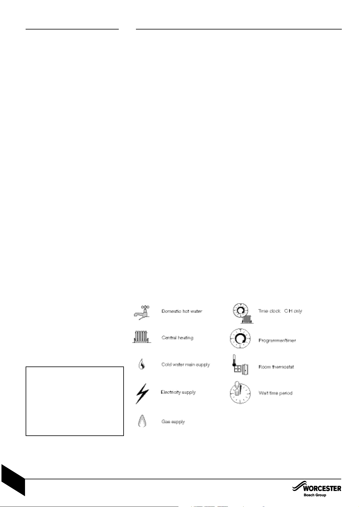
SYMBOLS USED IN THIS MANUAL:
WORCESTER:
TECHNICAL: 08705 266241
SERVIC E: 08457 256206
SPARES: 01905 752571
LITERATURE: 01905 752556
TRAINING: 01905 752526
SALES: 01905 752640
WEBSITE: www.worcester-bosch.co.uk
WATER TREATMENT:
FERNOX 01799 550811
www.fernox.com
SENTINEL 0151 420 9595
www.betzdearborn.com/sentinel
FLUE TERMINAL GUARD:
TOWER FLUE COMPONENTS
VALE RISE
TON BRIDG E
TN9 1TB
TEL: 01732 351680
FAX: 01732 354445
PLEASE READ THESE INSTRUCTIONS CAREFULLY BEFORE STARTING INSTALLATION.
THESE INSTRUCTIONS ARE APPLICABLE TO THE WORCESTER APPLIANCE MODEL(S)
STATED ON THE FRONT COVER OF THIS MANUAL ONLY AND MUST NOT BE USED WITH
ANY OTHER MAKE OR MODEL OF APPLIANCE.
THE INSTRUCTIONS APPLY IN THE UK ONLY AND MUST BE FOLLOWED EXCEPT FOR ANY
STATUTORY OBLIGATION.
THIS APPLIANCE MUST BE INSTALLED BY A COMPETENT PERSON. FAILURE TO INSTALL
CORRECTLY COULD LEAD TO PROSECUTION.
IF YOU ARE IN ANY DOUBT CONTACT THE WORCESTER TECHNICAL HELPLINE.
DISTANCE LEARNING AND TRAINING COURSES ARE AVAILABLE FROM WORCESTER.
PLEASE LEAVE THESE INSTRUCTIONS WITH THE COMPLETED BENCHMARK
CHECKLIST, (OR A CERTIFICATE CONFIRMING COMPLIANCE WITH IS 813, EIRE ONLY)
AND THE USER MANUAL WITH THE OWNER OR AT THE GAS METER AFTER INSTALLATION OR SERVICING. THE BENCHMARK CHECKLIST CAN BE FOUND IN THE BACK TWO
PAGES OF THE INSTALLATION MANUAL.
ABBREVIATIONS USED IN THIS MANUAL:
Ø Diameter
NG Natural Gas
LPG Liquid Petroleum Gas
CH Central Heating
DHW Domestic Hot Water
IP Ingress Protection
SEDBUK Seasonal Efficiency of Domestic Boilers in the United Kingdom
CONTACT INFORMATION INSTALLATION & SERVICING INSTRUCTIONS
LIFTING AND CARRYING PRECAUTIONS:
• Lift only a manageable weight, or ask for
help.
• When lifting the boiler, bend the knees,
and keep the back straight and feet apart.
• Do not lift and twist at the same time.
• Lift and carry the boiler close to the body
• Wear protective clothing and gloves to
protect from any sharp edges
INSTALLATION &
SERVICING INSTRUCTIONS
INSTALLATION & SERVICI NG INSTRUCTIONS FOR WORC ESTER GR EENSTAR 24 i junior/28 i junior
8 716 107 336b (11/05)
1
STORE THE APPLIANCE IN A DRY
AREA PRIOR TO INSTALLATION.
Page 3

SAFETY & REGULATIONS
SAFETY PRECAUTIONS & SYMBOLS 3
INSTALLATION REGULATIONS 3
APPLIANCE INFORMATION
GENERAL INFORMATION 4
TECHNICAL DATA 5
LAYOUT & COMPONENTS 6-7
PRE-INSTALLATION
CLEANING PRIMARY SYSTEMS 8
MAINS SUPPLY 9
WATER SYSTEMS & PIPEWORK 10
CONDENSATE PIPEWORK 11
PRESSURE RELIEF PIPEWORK 12
BOILER LOCATION & CLEARANCES 13-14
PLUMBING MANIFOLD 15
FLUE TERMINAL POSITIONS 16
FLUE OPTIONS 17
INSTALLATION
UNPACKING THE WALL FRAME 18
WALL MOUNTING TEMPLATE / FLUE OPENING 19
UNPACKING THE APPLIANCE 20
BOILER CONNECTIONS 21-22
FLUE INSTALLATION 23-25
CONDENSATE CONNECTIONS 26
ELECTRICS 27
POSITION OF WIRED COMPONENTS 28
COMMISSIONING
PRE-COMMISSIONING CHECKS 29
FILLING THE SYSTEM 30
STARTING THE APPLIANCE 31
WATER TREATMENT 32
COMMISSIONING 33
FINISHING COMMISSIONING 34
SERVICING & SPARES
INSPECTION AND SERVICE 35-40
REPLACEM ENT OF PARTS 41-50
SETTING THE GAS/AIR RATIO 51
SHORT PARTS LIST 52
CONVERSION KITS
L.P.G. CONVERSION 53
FAULT FINDING & DIAGNOSIS
FAULT FINDING 54
CH FUNCTION 55
DHW FUNCTION 56
PROTECTION FUNCTION 57-58
BENCHMARK CHECKLIST
SERVICE INTERVAL RECORD SHEET
CONTENTS
CONTENTS
INSTALLATION & SERVICI NG INSTRUCTIONS FOR WORC ESTER GR EENSTAR 24 i junior/28 i junior
8 716 107 336b (11/05)
2
SAFETY &
REGULATIONS
APPLIANCE
INFORMATION
PRE -
INSTALLATION
INSTALLATIONCOMMISSIONING
SERVICING
& SPARES
CONVERSION
KITS
FAULT FINDING
& DIAGRAMS
Page 4

SAFETY PRECAUTIONS
& INSTALLATION REGULATIONS
INSTALLATION & SERVICI NG INSTRUCTIONS FOR WORC ESTER GR EENSTAR 24 i junior/28 i junior
8 716 107 336b (11/05)
3
SAFETY &
REGULATIONS
SAFETY PRECAUTIONS INSTALLATION REGULATIONS
IF YOU SMELL GAS:
✗ DON’T SMOKE OR STRIKE MATCHES
✗ DON’T TURN ELECTRICAL SWITCHES ON OR OFF
✓DO PUT OUT NAKED FLAMES
✓DO OPEN DOORS AND WINDOWS
✓DO KEEP PEOPLE AWAY FROM THE AREA AFFECTED
✓DO TURN OFF THE CONTROL VALVE AT THE METER
✓DO CALL YOUR GAS COMPANY
A Benchmark Checklist is provided by the manufacturer for the installer to complete
including their CORGI registration number to confirm that the boiler has been installed,
commissioned and serviced according to the manufacturer’s instructions.
IMPORTANT: The completed Benchmark Checklist will be required in the event of any
warranty work and may be required by the local Building Control Inspector.
HEALTH & SAFETY
The appliance contains no asbestos and no substances have been used in the
construction process that contravene the COSHH Regulations (Control of Substances
Hazardous to Health Regulations 1988).
COMBUSTIBLE AND CORROSIVE MATERIALS
Do not store or use any combustible materials (paper, thinners, paints etc.) inside or
within the vicinity of the appliance.
Chemically aggressive substances, such as halogenated hydrocarbons containing
chlorine or fluorine compounds can corrode the appliance and invalidate any warranty.
FITTING & MODIFICATIONS
Fitting the appliance and any controls to the appliance may only be carried out by a
competent engineer in accordance with the current Gas Safety (Installation and Use)
Regulations.
Flue systems must not be modified in any way other than as described in the fitting
instructions. Any misuse or unauthorised modifications to the appliance, flue or
associated components and systems could invalidate the warranty. The manufacturer
accepts no liability arising from any such actions, excluding statutory rights.
SERVICING
Advise the user to have the system serviced annually by a competent, qualified
engineer (such as British Gas or CORGI registered personnel) using approved spares,
to help maintain the economy, safety and reliability of the appliance.
IMPORTANT - The service engineer must complete the Service Record on the
Benchmark Checklist after each service.
Gas Safety (Installation & Use) Regulations 1998:
All gas appliances must be installed by a
competent person in accordance with the above
regulations. Failure to install appliances correctly
could lead to prosecution.
The appliance must be installed in accordance
with, and comply to, the current: Gas Safety
Regulations, IEE Regulations, Building
Regulations, Building Standards (Scotland)
(Consolidation), Building Regulations (Northern
Ireland), local water by-laws, Health & Safety
Document 635 (The Electricity at Work
Regulations 1989) and any other local
requirements.
British Standards:
The relevant British Standards should be followed,
including:
BS7074:1 : Code of practice for domestic and hot
water supply
BS6891 : Installation of low pressure gas
pipework up to 28mm (R1)
BS5546 : Installation of gas hot water supplies for
domestic purposes
EN:12828 : Central heating for domestic premises
BS5440:1 : Flues and ventilation for gas appliances of rated heating not exceeding 70kW (net) :
Flues
BS5440:2 : Flues and ventilation for gas appliances of rated heating not exceeding 70kW (net) :
Air Supply
BS7593 : Treatment of water in domestic hot
water central heating systems
BS 6798 : Installation of gas fired boilers of rated
input up to 70kW (net)
Where no specific instruction is given, reference
should be made to the relevant British Standard
codes of Practice.
L.P.G. Installation:
An appliance using L.P.G. must not be installed in
a room or internal space below ground level unless
one side of the building is open to the ground.
Timber framed buildings:
Where the boiler is to be fitted to a timber framed
building the guidelines laid down in BS5440: Part
1 and IGE "Gas Installations in Timber Frame
Buildings” should be adhered to.
Potable water:
All seals, joints and compounds (including flux and
solder) and components used as part of the
secondary domestic water system must be
approved by WRAS.
CH water:
Artificially softened water must not be used to fill
the central heating system.
Page 5
GENERAL INFORMATION
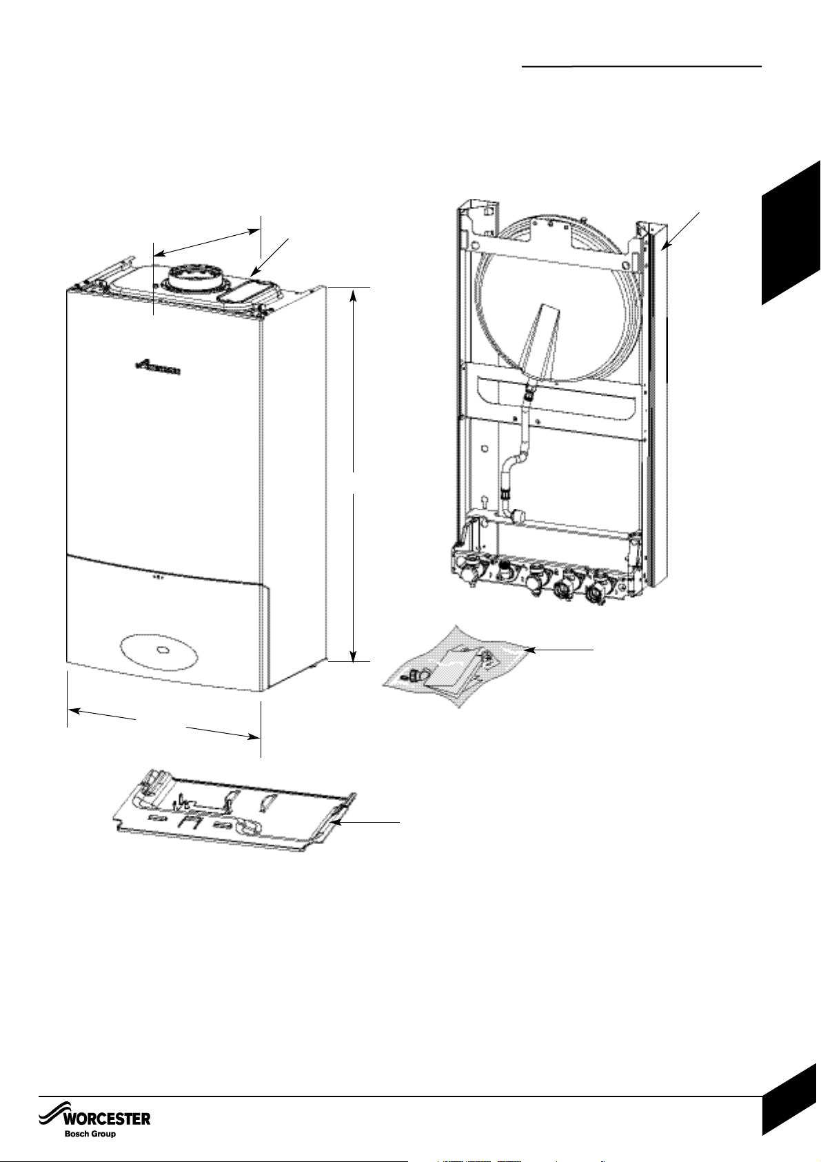
STANDARD PACKAGE:
A - Wall hung gas fired condensing combi boiler for
central heating and domestic hot water
B - Boiler support frame
C -Hardware literature pack
D - Bottom Panel
SPECIFICATIONS:
Pre-wired and pre-plumbed
Galvanised steel inner frame
Digital control system
Automatic ignition
Direct burner ignition electrodes
Built-in frost thermostat
Built-in fault finding diagnostics
Modulating automatic gas valve
Combustion air fan with speed regulator
CH temperature sensor & control
Pump anti-seizure protection
Flue gas temperature limiter
Condensate trap & syphon
DHW flow sensor
Plate type DHW heat exchanger
700mm
400mm
A
D
330mm
GENERAL INFORMATION
INSTALLATION & SERVICI NG INSTRUCTIONS FOR WORC ESTER GR EENSTAR 24 i junior/28 i junior
8 716 107 336b (11/05)
4
APPLIANCE
INFORMATION
B
C
D
(When fitted to wall frame)
Depth to wall
Page 6

TECHNICAL DATA
INSTALLATION & SERVICI NG INSTRUCTIONS FOR WORC ESTER GR EENSTAR 24 i junior/28 i junior
8 716 107 336b (11/05)
5
TECHNICAL DATA
APPLIANCE
INFORMATION
Domestic Hot Water
Min. heat input KW 7.38 7.38 9.64 9.64
Max. rated heat output KW 24 28 24 28
Max. rated heat input KW 24.49 28.57 24.49 28.57
Gas flow rate - Max. 10 minutes from lighting
Natural Gas G20 m
3
/h 2.59 3.02 - -
Propane Gas (LPG) kg/h - - 1.9 2.22
Max. mains inlet pressure bar 10 10 10 10
Min. mains inlet pressure (working) for max flow bar 1.3 1.3 1.3 1.3
Min. mains inlet pressure (working) for operation bar 0.2 0.2 0.2 0.2
Domestic Hot Water temperature setting °C 55 55 55 55
Domestic Hot Water specific rate - 30°C rise l/min 11.5 13.4 11.5 13.4
Max. Domestic Hot Water flow rate - 40°C rise +/— 15% l/min 8.6 10 8.6 10
Central Heating
Max. rated heat input KW 24.62 24.62 24.62 24.62
Max. rated heat output 40/30°C KW 25.67 25.67 25.67 25.67
Max. rated heat output 50/30°C KW 25.45 25.45 25.45 25.45
Max. rated heat output 80/60°C KW 24 24 24 24
Max. flow temperature °C 82 82 82 82
Max. permissible operating pressure bar 2.5 2.5 2.5 2.5
Available pump head at 21°C system temperature rise m 2.0 2.0 2.0 2.0
Flue
Flue Gas Temp. 80/60°C, rated/min. load °C 78/63 78/64 79/64 79/65
Flue Gas Temp. 40/30°C, rated min. load °C 54/35 54/36 55/38 55/39
CO
2
level at max. rated heat output % 9.8 9.8 11.0 11.0
CO2level at min. rated heat output % 9.2 9.2 10.5 10.5
NOx - class 5555
Condensate
Max. condensation rate l/h 2.0 2.0 2.0 2.0
pH value, approx. 4.8 4.8 4.8 4.8
Electrical
Electrical power supply voltage AC...V 230 230 230 230
Frequency Hz 50 50 50 50
Max. power consumption W 140 140 140 140
General Data
SEDBUK band AAAA
Appliance protection rating IP X4D X4D X4D X4D
Appliance protection rating with mechanical or RF mechanical timer fitted IP 20 20 20 20
Permissible ambient temperatures °C 0-50 0-50 0-50 0-50
Nominal capacity of appliance Itr 3.9 3.9 3.9 3.9
Noise output level (Max central heating) dB(A) 42 42 42 42
Packaged boiler weight kg 44.4 44.4 44.4 44.4
Total boiler weight kg 39.5 39.5 39.5 39.5
Lift weight kg 27.1 27.1 27.1 27.1
SEDBUK % 90.1 90.1 91.8 91.8
DESCRIPTION NATURAL GAS L.P.G.
UNITS 24i junior 28i junior 24i junior 28i junior
Page 7
LAYOUT & COMPONENTS
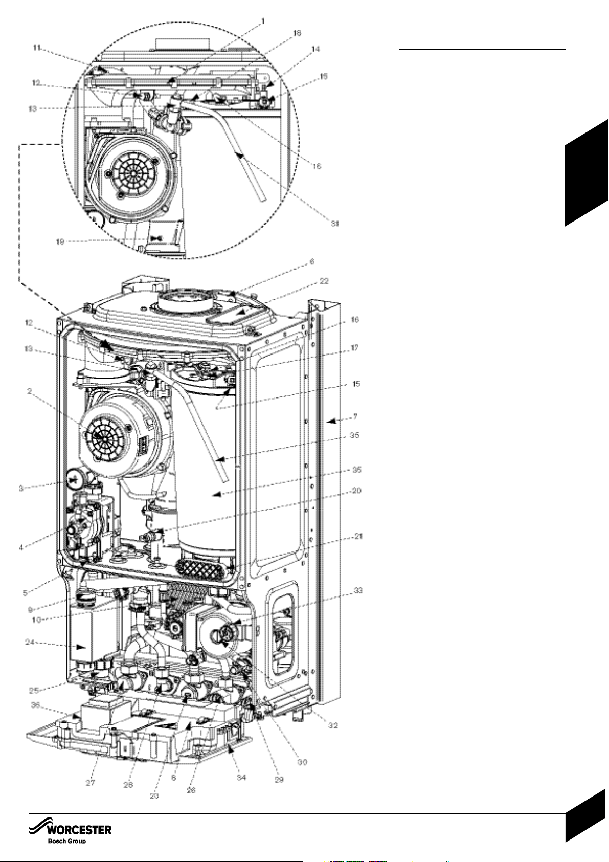
The diagram opposite shows the controls in the
servicing position and excludes the outer case.
1 AIR / GAS MANIFOLD
2FAN
3 AIR / GAS ADJUSTMENT SCREW
4GAS VALVE
5 INLET PRESSURE TEST POINT
6 EXPANSION VESSEL
7 WALL MOUNTING FRAME
8 COVER FOR EXTERNAL WIRING
CONNECTIONS
9 CONDENSATE CONNECTION FROM
HEAT EXCHANGER
10 PLATE TO PLATE
DHW HEAT EXCHANGER
11 FLUE PRESSURE SWITCH
12 FAN PRESSURE TEST POINT
13 MANUAL VENT POINT
14 IGNITION AND FLAME SENSE ELECTRODES
15 OVERHEAT THERMOSTAT
16 FLAME VIEWING MIRROR
17 SECURING NUT, AIR /
GAS MANIFOLD CLAMP
18 SENSOR - BOILER FLOW
19 FLUE AIR PRESSURE SWITCH
CONNECTION
20 FLUE OVERHEAT THERMOSTAT
21 ACCESS POINT FOR CLEANING HEAT
EXCHANGER/SUMP
22 REMOVABLE TOP CASE PANEL FOR
SERVICING
23 GAS INLET CONNECTION 22mm
COMPRESSION
24 TRAP / SYPHON
25 TRAP / SYPHON OUTLET
CONNECTION ( 22mm PLASTIC PIPE)
26 MAINS COLD WATER IN
27 CH FLOW
28 DHW OUT
29 CH RETURN
30 DRAIN POINT
31 SILICONE TUBE (USE TO VENT AIR
FROM HEAT EXCHANGER)
32 PUMP
33 SYSTEM PRESSURE GAUGE
34 CONTROL PANEL IN SERVICE
POSITION
35 HEAT EXCHANGER
36 ACCESS COVER FOR TRANSFORMER &
PCB
LAYOUT & COMPONENTS
INSTALLATION & SERVICI NG INSTRUCTIONS FOR WORC ESTER GR EENSTAR 24 i junior/28 i junior
8 716 107 336b (11/05)
6
APPLIANCE
INFORMATION
Page 8
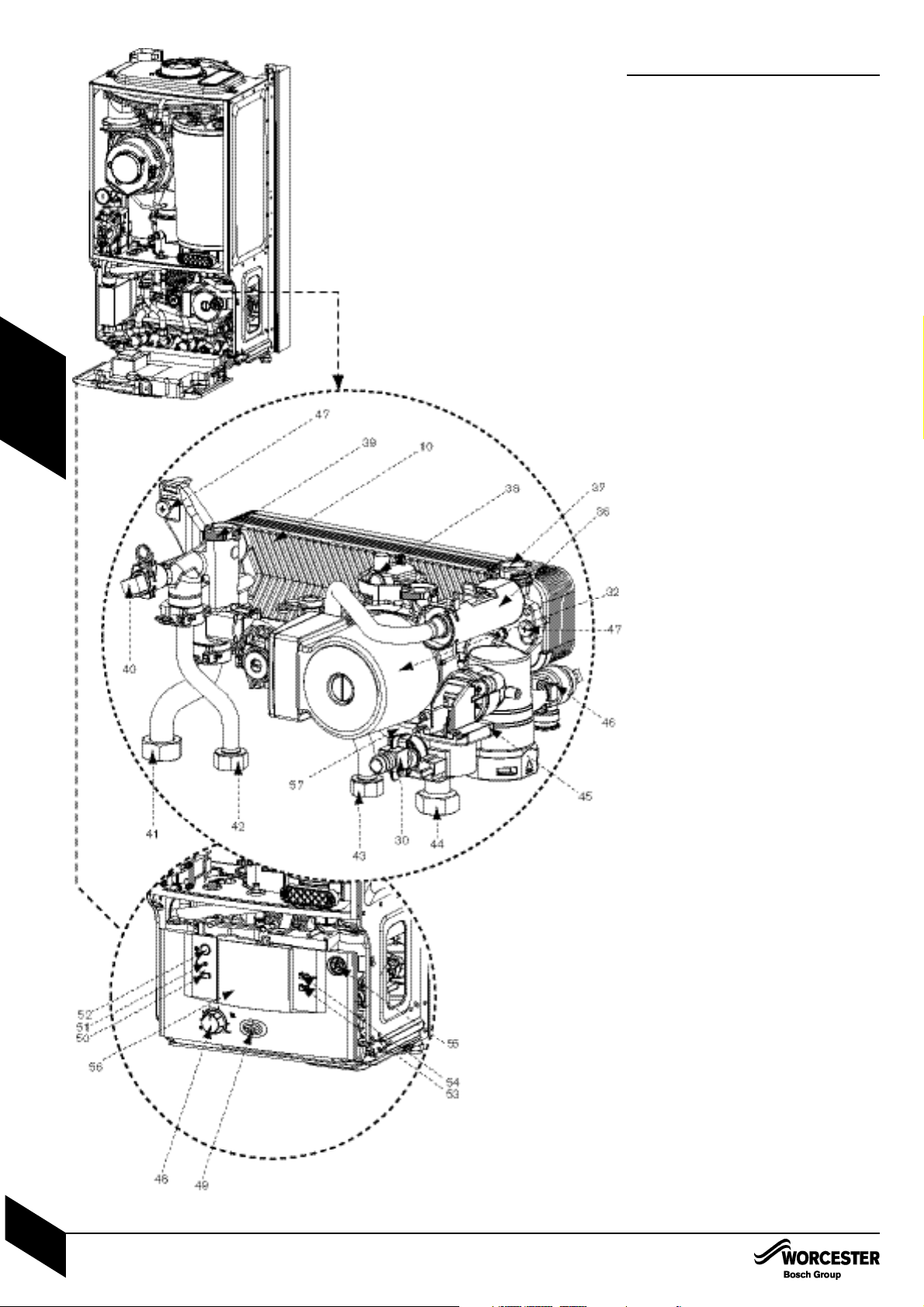
LAYOUT & COMPONENTS
10 PLATE TO PLATE DHW
HEAT EXCHANGER
32 SYSTEM PUMP
36 FLOW TURBINE
37 UNUSED PORT
38 AUTO AIR VENT
39 FLOW CONNECTION FROM BOILER
HEAT EXCHANGER
40 DHW SENSOR
41 CH FLOW CONNECTION TO
SERVICE VALVE
42 DHW OUT CONNECTION
43 COLD WATER IN CONNECTION
44 CH RETURN CONNECTION TO
SERVICE VALVE
45 DIVERTER VALVE
46 PRESSURE RELIEF VALVE
47 COMPACT HYDRAULIC MOUNTING
SCREW (2) TO BOILER
48 CH TEMPERATURE CONTROL
49 MAINS ON/OFF INDICATOR/
DIAGNOSTIC LIGHT (BLUE)
50 SERVICE MODE BUTTON
51 BURNER ON INDICATOR LIGHT (GREEN)
52 MASTER SWITCH ON/OFF
53 ECO BUTTON
54 FAULT RESET BUTTON
55 SYSTEM PRESSURE GAUGE
56 POSITION FOR OPTIONAL
PROGRAMMER
57 INTERNAL BY-PASS WITHIN
PLASTIC MOULDING
LAYOUT & COMPONENTS
INSTALLATION & SERVICI NG INSTRUCTIONS FOR WORC ESTER GR EENSTAR 24 i junior/28 i junior
8 716 107 336b (11/05)
7
APPLIANCE
INFORMATION
Page 9

CLEANING PRIMARY SYSTEMS
BEFORE CLEANING THE SYSTEM:
ENSURE TH E SYSTEM AND PIPEWORK IS
IN GOOD WORKING ORDER
KEEP THE EXISTING BOILER/
CIRCULATING PUMP WHERE POSSIBLE
OR USE A POWER FLUSHING MACHINE
TO AID THE CLEANSING PROCEDURE
BEFORE INSTALLING A NEW BOILER.
CLEANING THE PRIMARY SYSTEM:
1 Fill the system with cold water and
check for leaks.
2 Open all drain cocks and drain the
system.
3 Close drain cocks and add a suitable
flushing agent compatible with
aluminium at the correct strength for
the system condition in accordance with
the manufacturer's instructions.
The PH value of the system water
must be less than 8 or the appliance
guarantee will be invalidated.
Circulate the flushing agent before the
boiler is fired up.
4 Run the boiler/system at normal operating
temperature as directed by the manufacturer
of the flushing agent.
5 Drain and thoroughly flush the system to
remove the flushing agent and debris.
IMPORTANT: All the following Pre-Installation sections must be read and
requirements met before starting boiler or flue installation.
CAUTION: ISOLATE THE MAINS SUPPLIES BEFORE STARTING ANY WORK AND
OBSERVE ALL RELEVANT SAFETY PRECAUTIONS.
IMPORTANT: Debris from the system can
damage the boiler and reduce efficiency.
Failure to comply with the guidelines for
the use of water treatment with the
appliance will invalidate the appliance
warranty.
CLEANING PRIMARY SYSTEMS
INSTALLATION & SERVICI NG INSTRUCTIONS FOR WORC ESTER GR EENSTAR 24 i junior/28 i junior
8 716 107 336b (11/05)
8
PRE -
INSTALLATION
Page 10
MAINS SUPPLY
ELECTRIC SUPPLY:
• Supply: 230V - 50Hz, 140 watts
• Cable: PVC insulated 0.75mm2(24 x 0.2mm)
temperature rated to 90°C.
• External 3A fuse to BS1362.
• The appliance must be earthed.
• IPX4D. NOTE: this is reduced to IP20 if the
following mechanical timers are fitted:
7 716 192 036 or 7 716 192 037.
• All pipes to the boiler must be cross-bonded.
• Wiring must comply with IEE wiring regulations.
GAS SUPPLY:
• Boilers using NG must be connected to a
governed meter.
• LPG boilers must be connected to a
regulator.
• Installation and connection of the gas supply
to the boiler must be in accordance with
BS6891.
• Under no circumstances should the size of
the gas supply pipe be less than that of the
appliance inlet connection.
• The meter or regulator and pipework to the
meter must be checked, preferably by the gas
supplier, to ensure it is in good working order
and can meet the gas flow and pressure
requirements in addition to the demand from
any other appliance being served.
WATER SUPPLY:
Water mains pressure:
• Minimum mains water pressure 1.3 bar for
maximum performance.
• Maximum mains fed water pressure 10 bar.
If necessary, fit a pressure reducing valve.
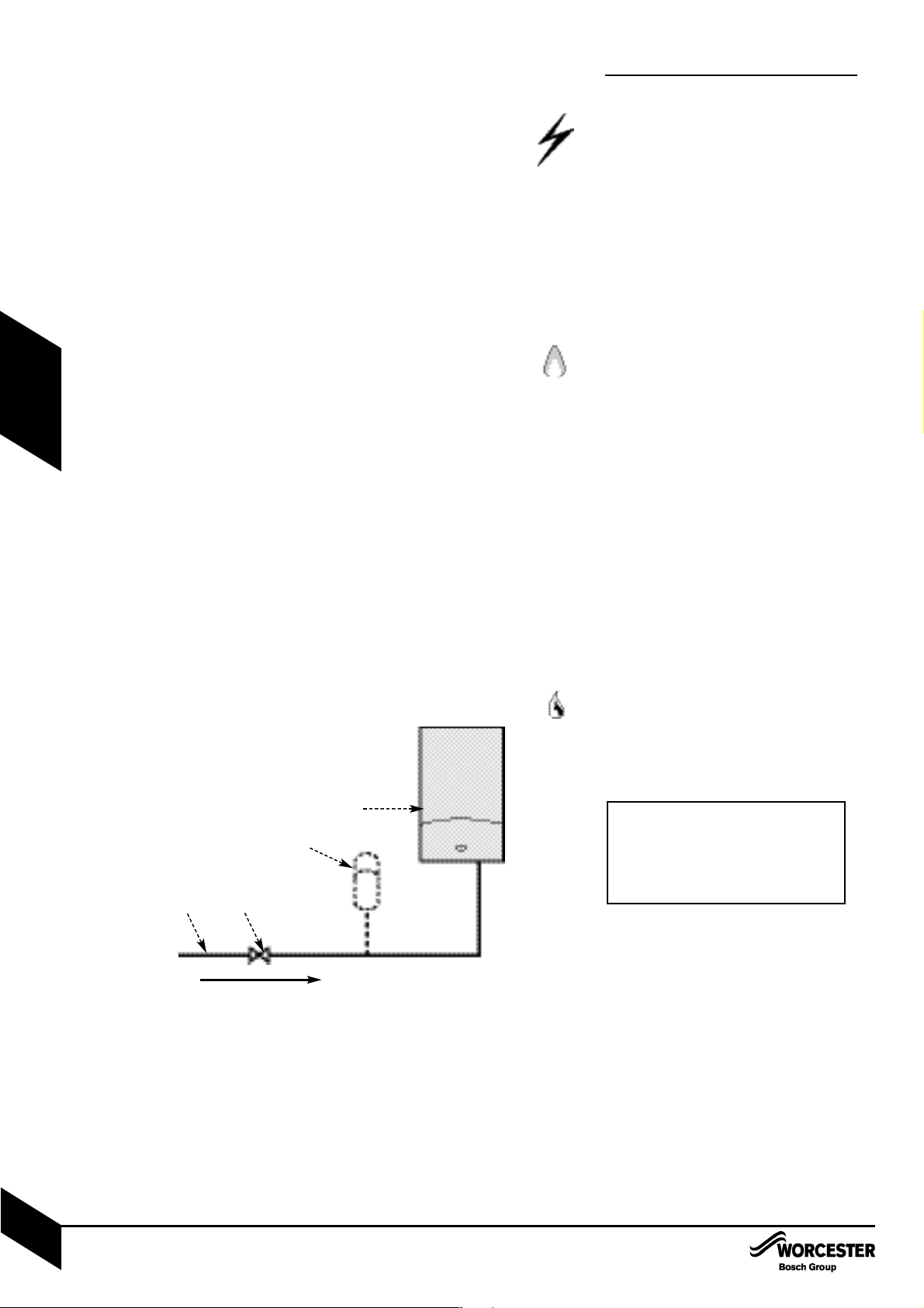
• Where the mains water supply has a nonreturn, back flow prevention valve fitted, a
mini expansion vessel (A) should be connected to the mains water inlet pipe (B) between
the non-return valve (C) and the boiler (D) as
shown opposite.
Use in hard water areas:
Normally there is no need for water treatment to
prevent scale formation as the maximum temperature of the DHW heat exchanger is limited
in the electronic circuit.
In areas where temporary water hardness
exceeds 200ppm, consideration may need to
be given to the fitting of a scale prevention
device. In such circumstances, the advice of
the local water authority should be sought.
IMPORTANT: Non-return, back flow prevention devices (including those associated with water meters) fitted to the
mains water supply can cause a pressure build up which could damage the
boiler and other household appliances.
MAINS SUPPLY
INSTALLATION & SERVICI NG INSTRUCTIONS FOR WORC ESTER GR EENSTAR 24 i junior/28 i junior
8 716 107 336b (11/05)
9
PRE -
INSTALLATION
MAINS WATER EXPANSION VESSEL:
A - Mini expansion vessel, part No. 7 716 102 105
B - Mains water inlet
C - Non-return valve
D - Boiler
A
B
C
D
Page 11
WATER SYSTEMS & PIPEWORK
PLASTIC PIPEWORK:
• Any plastic pipework must have a polymeric
barrier with 600mm (minimum) length of
copper or steel pipe connected to the boiler.
• Plastic pipework used for underfloor heating
must be correctly controlled with a
thermostatic blending valve limiting the
temperature of the circuits to approx. 50°C.
The pipework from the boiler to the blending
valve must be in copper or steel (protected
from corrosion).
PRIMARY SYSTEMS CONNECTIONS/VALVES:
• All system connections, taps and mixing
valves must be capable of sustaining a
pressure up to 3 bar.
• Radiator valves should conform to
BS2767:10.
• All other valves should conform to BS1010.
• Thermostatic radiator valves (TRV’s) must be
used on all radiators within the sleeping
accommodation but not the radiator where
the room thermostat is sited. This must be
fitted with lockshield valves and left open.
• A drain cock is required at the lowest point
in the system.
• An air vent is required at all the high points in
the system.
NOTE: The boiler is equipped with an automatic
internal by-pass.
SHOWERS/BIDETS:
• If a shower head can be immersed in water or
comes closer than 25mm from the top edge
of a bath or shower tray spill over level then
an anti-siphon device must be fitted to the
shower hose.
• Bidets with direct hot and cold mains water
can be used (with the approval of the local
water authority) and must be the over rim
flushing type with shrouded outlets to prevent
the fitting of hand held sprays.
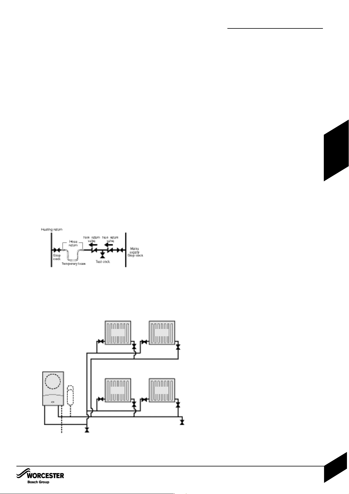
SEALED PRIMARY SYSTEM:
• The CH sealed system must be filled using a
WRAS approved filling loop or comply with
the diagram opposite for system fill.
• Where the system volume is more than 100
litres or exceeds 2.65 bar at maximum
heating temperature, an extra expansion
vessel (B) must be fitted as close as possible
to the appliance in the central heating return.
• Pressurise the extra expansion vessel (B) to
the same figure as the expansion vessel built
into the appliance.
• Do not use galvanised pipes or radiators.
INSTALLATIONCOMMISSIONING
TYPICAL SEALED SYSTEM
A - Appliance expansion vessel -
central heating
B - Extra expansion vessel -
central heating return
C - Drain cock
P - Pressure relief discharge
R - Radiators
SYSTEM FILL
B
A
P
C
C
R
R
R
R
WATER SYSTEMS & PIPEWORK
INSTALLATION & SERVICI NG INSTRUCTIONS FOR WORC ESTER GR EENSTAR 24 i junior/28 i junior
8 716 107 336b (11/05)
10
PRE -
INSTALLATION
Page 12
CONDENSATE PIPEWORK
CONDENSATE PIPEWORK:
• The condensate pipe must be a minimum of
22mmØ plastic pipe.
• The condensate pipework must fall at
least 50mm per metre towards the outlet
and should take the shortest practicable
route.
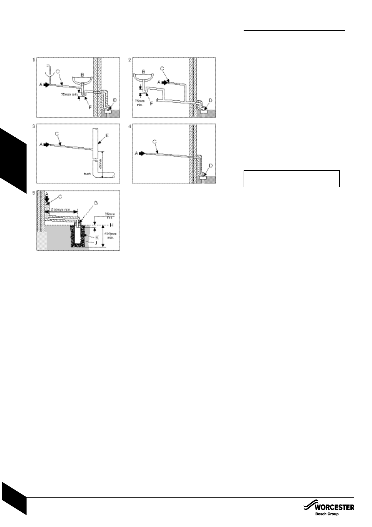
• The pipework must follow one of the options
shown opposite into an internal serviceable
trap (min. 75mm) such as a sink/washing
machine) or discharge direct into a vent
stack (E) 450mm min. above pipe invert or
into a gulley (D) below ground but above the
water level.
• Use waterproof pipe insulation in exposed
positions and for external pipework.
1 Internal sink/washing machine drain
2 Internal waste drainage system
3 Soil/vent stack
4 External drainage system
5 External condensate absorption point
A - Condensate from boiler
B - Sink
C - 22mmØ plastic condensate pipe
D - Gulley
E - Internal soil and vent stack
F - Serviceable waste trap (75mm min)
G - 300mm x 100mmØ sealed plastic tube
H - Ground level
J - Drainage holes 50mm from base of tube
(12mmØ at 25mm centres) facing away from
building
K - Limestone chippings
IMPORTANT: Ensure there are no
blockages in the pipe run.
CONDENSATE PIPEWORK
INSTALLATION & SERVICI NG INSTRUCTIONS FOR WORC ESTER GR EENSTAR 24 i junior/28 i junior
8 716 107 336b (11/05)
11
PRE -
INSTALLATION
Page 13
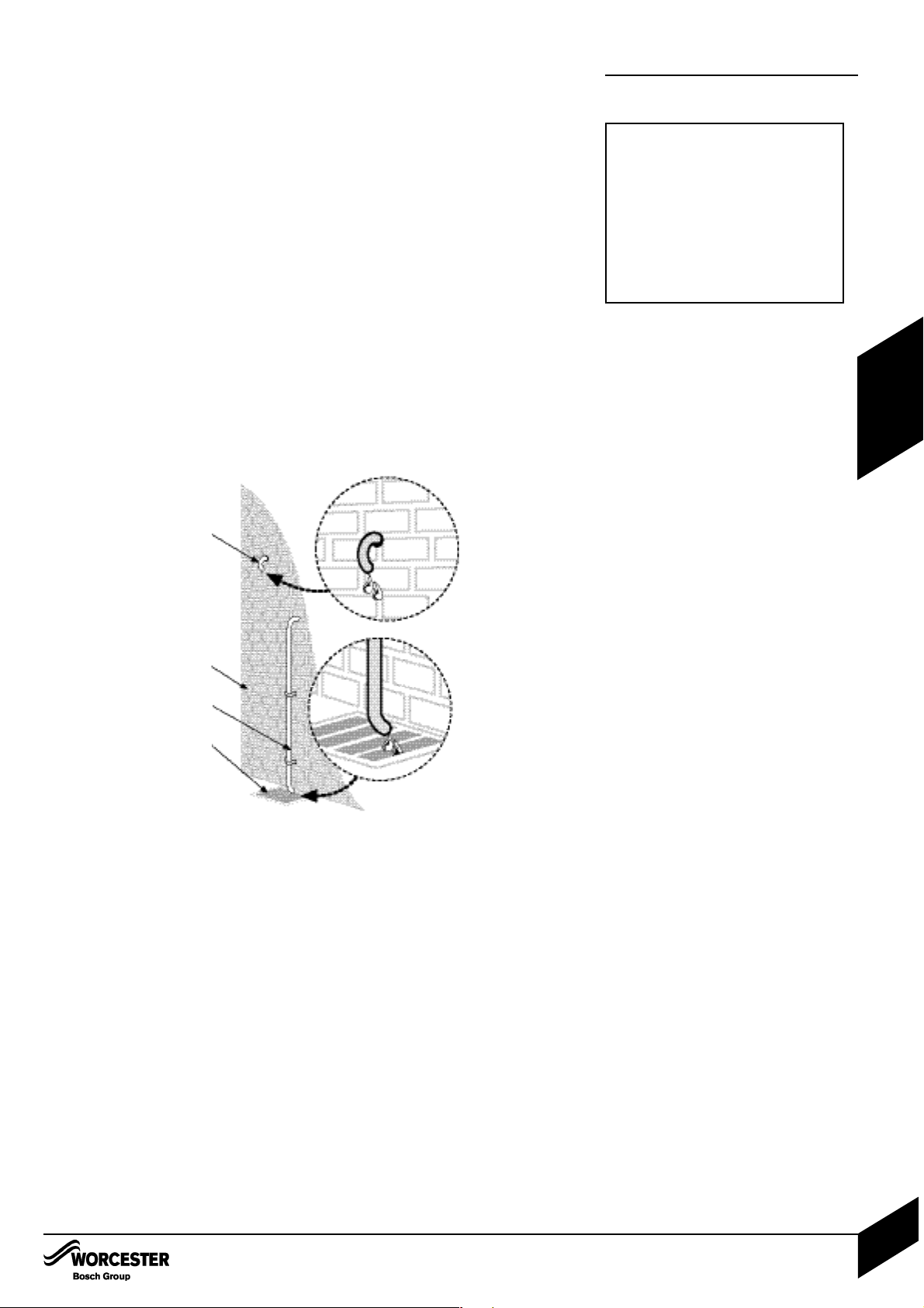
PRESSURE RELIEF PIPEWORK
PRESSURE RELIEF PIPEWORK:
• The pressure relief drain pipe (M) from the
boiler should be at least 15mm diameter
copper pipe and run downwards away from
any electrics or other hazard, preferably to an
external drain or soakaway.
• Pipe (M) should be finished with a partial
bend, near the outlet to face the external wall
(as shown) to help prevent freezing.
L - Outside wall
O,M - Drain pipe
N - External drain
IMPORTANT: The pressure relief valve
is a safety device for the boiler and if
activated may discharge boiling water
steam through the relief valve drain
pipe.
Care should be taken when siting the
outlet pipe so that it does not cause an
obstruction or discharge above a
window, entrance or other public access
where it could cause a hazard.
PRESSURE RELIEF PIPEWORK
INSTALLATION & SERVICI NG INSTRUCTIONS FOR WORC ESTER GR EENSTAR 24 i junior/28 i junior
8 716 107 336b (11/05)
12
PRE -
INSTALLATION
M
N
O
L
Page 14
BOILER LOCATION & CLEARANCES
INSTALLATION & SERVICI NG INSTRUCTIONS FOR WORC ESTER GR EENSTAR 24 i junior/28 i junior
8 716 107 336b (11/05)
13
PRE -
INSTALLATION
BOILER LOCATION &
CLEARANCES
This boiler is only suitable for installing internally
within a property at a suitable location onto a
fixed, rigid non-combustible surface at least the
same size as the boiler and capable of supporting the boiler weight.
COMPARTMENTS:
Follow the requirements of BS6798 and
BS5440 Part 2 and note:
• Minimum clearances must be maintained
• An access door is required to install, service
and maintain the boiler and any ancilliary
equipment.
• If fitting the boiler into an airing cupboard
use a non-combustible perforated material
(maximum hole sizes of 13mm) to separate
the boiler from the airing space.
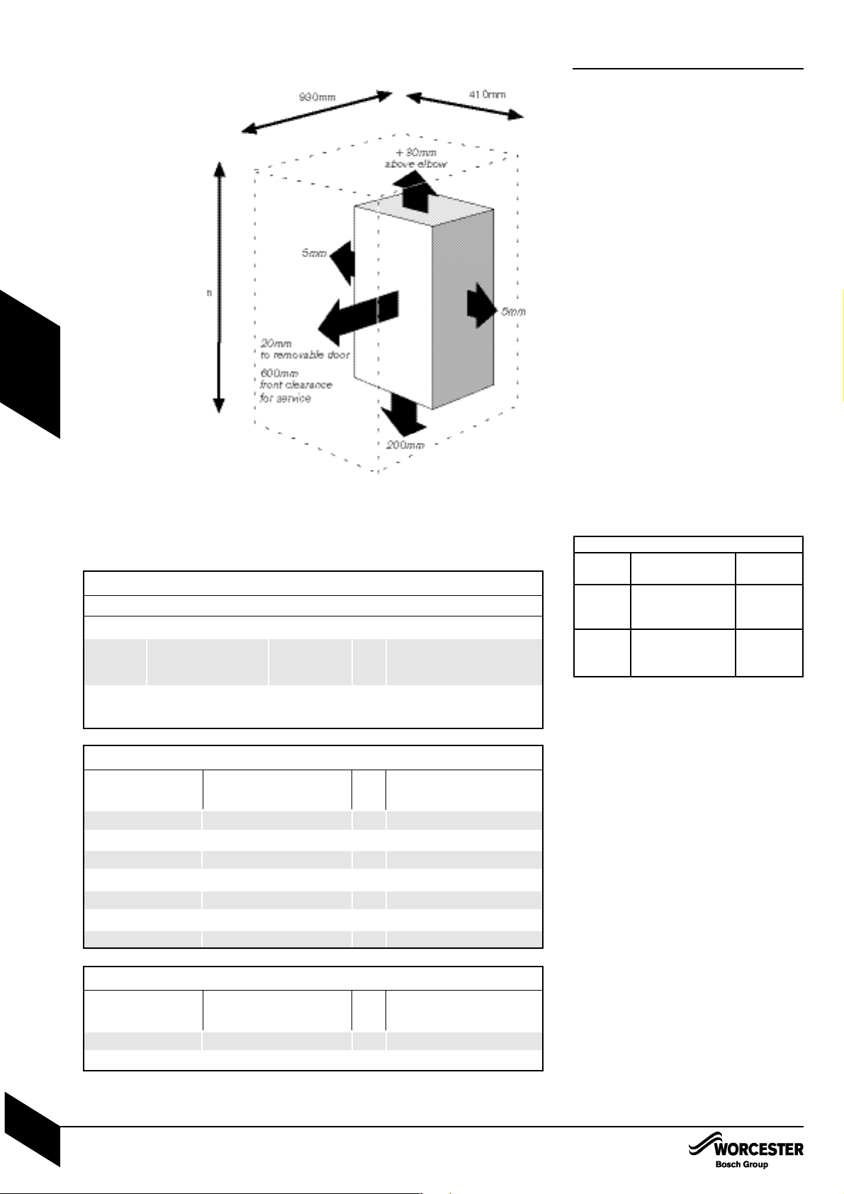
BOILER CLEARANCES:
The diagram opposite shows the minimum
space required to install and service the boiler.
If a boiler is installed in a compartment with
clearances less than shown in the tables opposite, ventilation is required. Refer to tables
below for ventilation requirements.
BOILER CLEARANCES - UNVENTILATED
COMPARTMENTS:
The tables opposite show the options for the
minimum space required to install and service
the boiler inside an unventilated compartment.
24 & 28 kW
Vent To room or Direct to
position internal space outside
High Minimum free Minimum
level area 122 cm
2
free area
61 cm
2
Low Minimum free Minimum
level area 122 cm
2
free area
61cm
2
SERVICING CLEARANCES
VENTED COMPARTMENT
VENTILATION FREE COMPARTMENTS
INSTALLATION CLEARANCES
Using 100mm flue kit
1080mm
Using 125mm flue kit
- 1110mm
Ventilation Free Compartments Installation Clearances
The suggested total unventilated compartment minimum clearances are:
Side Above Below Front (to removable door)
400mm 170mm approx. 200mm 100mm
(30mm above
the elbow)
(Note: Top and bottom clearances must not be reduced below these values as they are the
minimum required for servicing).
If Side Clearances are Reduced
350mm 441mm 129mm
300mm 523mm 161mm
250mm 617mm 200mm
200mm 727mm 243mm
150mm 856mm 295mm
100mm 1012mm 358mm
50mm 1202mm 434mm
If total side clearance is
reduced to:
Then overall height clearances
must be increased to (approx):
OR
Front clearance (to removable
door) must be increased to:
If Front Clearance is Reduced
50mm 511mm 505mm
25mm 596mm 569mm
If front clearance (to
removable door) is
reduced to:
Then overall height clearances
must be increased to (approx):
OR
Total side clearance must be
increased to:
Page 15
BOILER LOCATION & CLEARANCES
INSTALLATION & SERVICI NG INSTRUCTIONS FOR WORC ESTER GR EENSTAR 24 i junior/28 i junior
8 716 107 336b (11/05)
14
PRE -
INSTALLATION
1
1
2
3
2
3
1
1
2
3
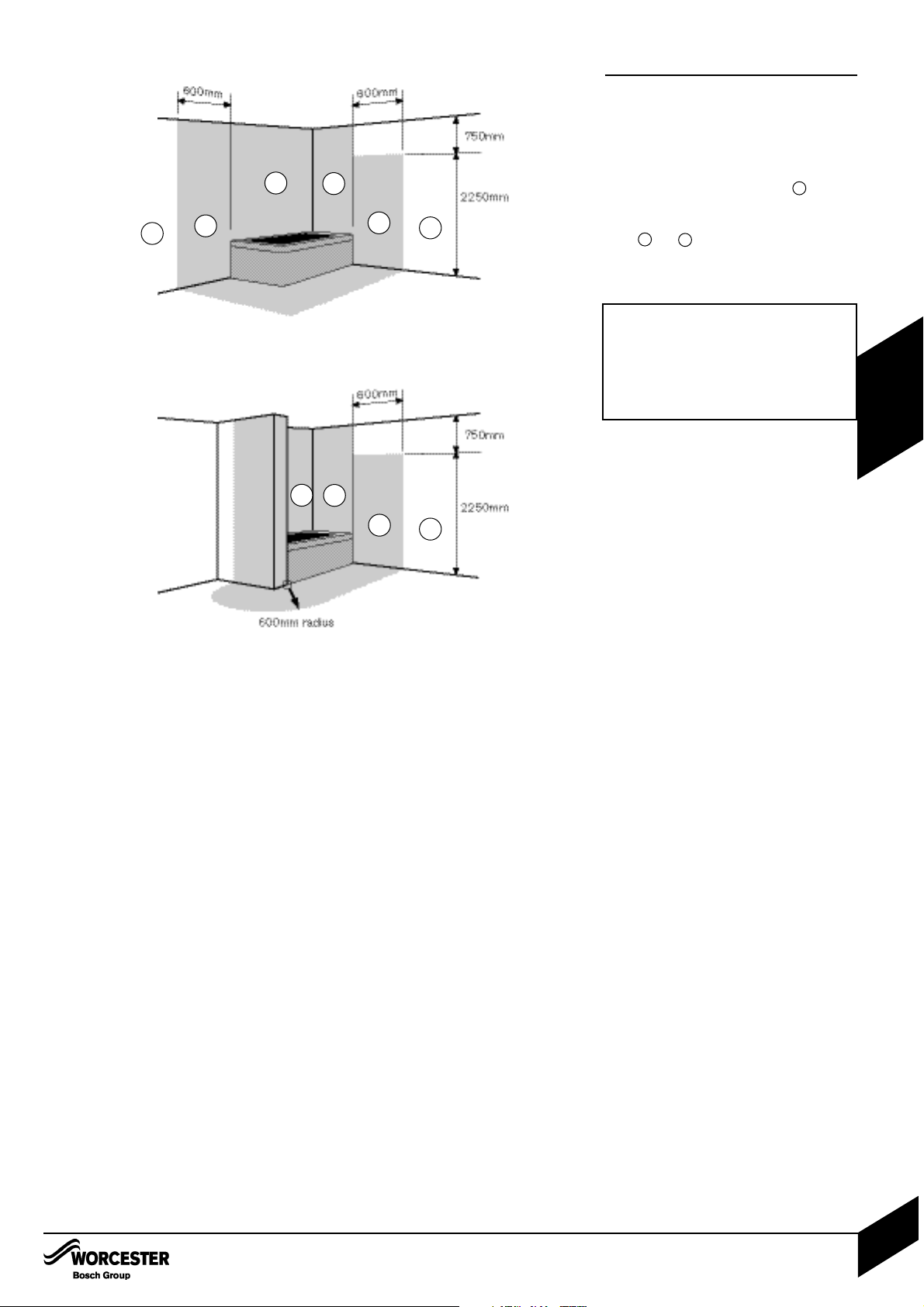
BATHROOMS:
If the appliance is fitted in conjunction with a
mechanical or RF mechanical timer, the
appliance can only be fitted in zone 3 .
Otherwise the appliance can be fitted in both
zones 2 and 3 .
See IEE wiring regulations.
BOILER LOCATION &
CLEARANCES
IMPORTANT: any switch or appliance
control using mains electricity must not be
able to be touched by a person using the
bath or shower.
Electrical switches, fused spur and socket
outlets must not be situated in the
bathroom.
Page 16
PLUMBING MANIFOLD
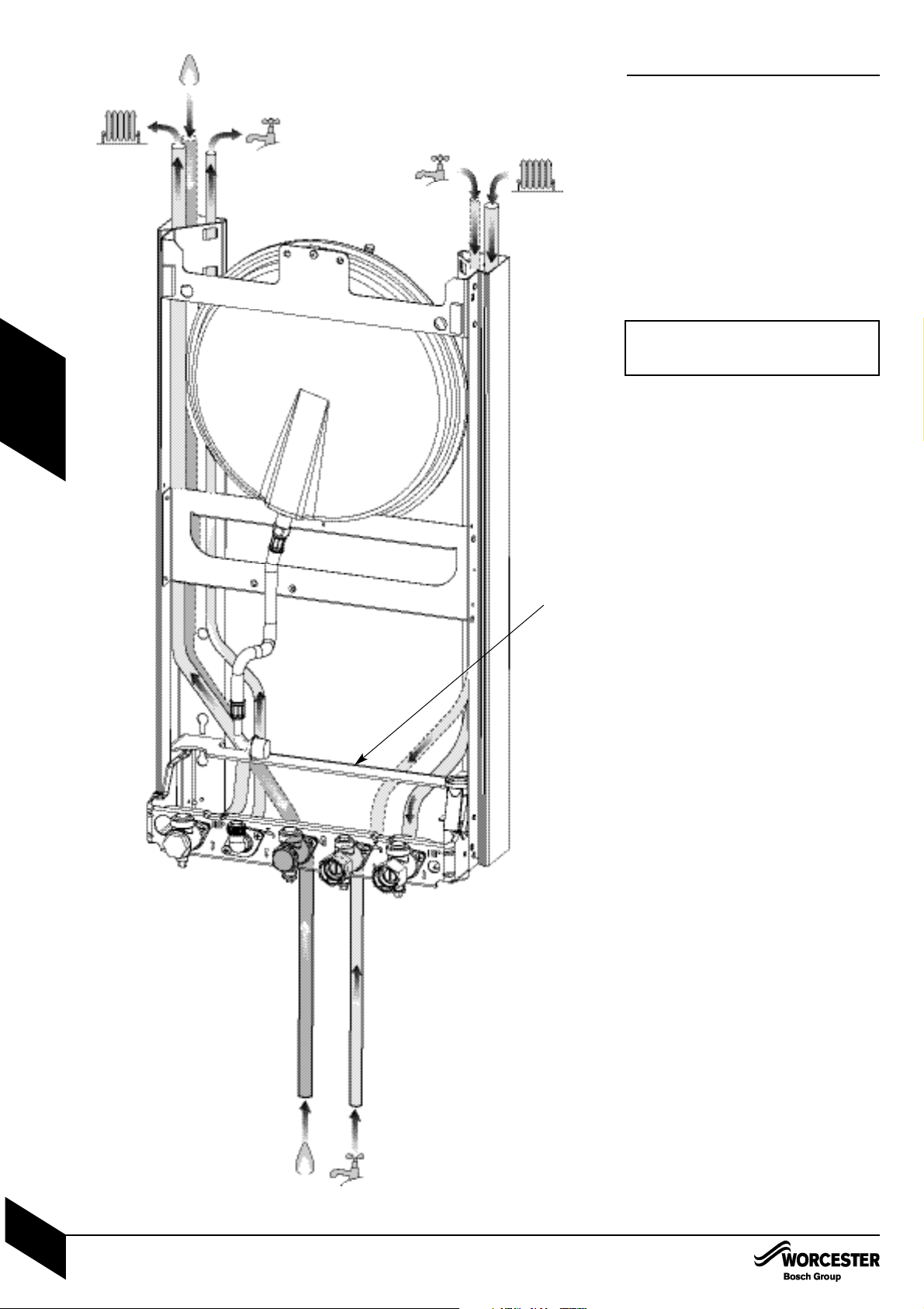
CONNECTIONS:
Heating System: 22mm compression fittings
DHW: 15mm compression fittings
Gas: 22mm compression fittings
Use the fittings supplied in the Lit/Hardware
pack.
• If the boiler pipes are to be run behind the
appliance ensure that the pipes pass through
the slot in the yellow plastic guide (A). This is
fitted to the boiler frame.
*
CH Return 22mm
CH Flow 22mm
PLUMBING MANIFOLD
INSTALLATION & SERVICI NG INSTRUCTIONS FOR WORC ESTER GR EENSTAR 24 i junior/28 i junior
8 716 107 336b (11/05)
15
PRE -
INSTALLATION
DHW OUT 15mm
DHW IN (alternative from
above appliance)
15mm
Gas Supply (alternative from above appliance) 22mm
Mains Gas Supply 22mm
Mains Water (DHW IN) 15mm
A
Further guidance on pipe routing can be
found printed on the boiler template
(supplied with the boiler).
Page 17
PRE -
INSTALLATION
FLUE TERMINAL POSITIONS
• The flue must be fitted and terminated in
accordance with the recommendations of
BS5440 : Part 1.
• The flue must not cause an obstruction.
• Discharge and any noise from the flue outlet
must not cause a nuisance.
• Flue gases have a tendency to plume and in
certain weather conditions a white plume of
condensation will be discharged from the flue
outlet. This could be a nuisance, for example,
near security lighting.
• The air inlet/outlet duct and the terminal of
the boiler must not be closer than 25mm to
any combustible material.
Detailed recommendations on protection of
combustible materials are given in
BS 5440:1.
• A protective terminal guard must be fitted if
the terminal is 2m or less above a surface
to which people have access.
The guard must be spaced equally (minimum
50mm) around the flue and fixed to the wall
with plated screws.
See Contact Information (inside front cover).
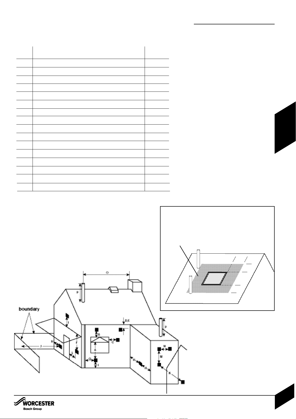
Minimum dimensions of flue terminal positions for balanced room sealed flues with
fanned draught:
DRWG. TERMINAL POSITION DISTANCE
REF:
A
1
Directly below an opening, air brick, opening windows, etc. 300mm
B
1
Above an opening, air brick, opening window, etc. 300 mm
C
1
Horizontally to an opening, air brick, opening window, etc. 300 mm
D Below gutters, soil pipes or drain pipes 75mm
E Below eaves 200mm
F
2
Below balconies or car port roof (lowest point) 200mm
G From a vertical drain pipe or soil pipe 150mm
H From internal or external corner or to a boundary alongside the terminal 300mm
I Above ground, roof or balcony 300mm
J From a surface or boundary facing the terminal 600mm
K From a terminal facing the terminal 1200mm
L
2
From an opening in the car port (e.g. door, window) into the dwelling 1200mm
M Vertically from a terminal on the same wall 1500mm
N Horizontally from a terminal on the same wall 300mm
O From a non combustible vertical structure on the roof
P Above intersection with the roof
1 In addition, the terminal should not be nearer than 150mm (fanned draught)
to an opening in the building fabric formed for the purpose of accommodating
a built-in element such as a window frame.
2 Not recommended.
See instructions supplied with vertical flue kits.
Care should be taken to ensure terminal siting
does not cause a nuisance to adjacent properties.
*
*
*
**
**
**
600mm
600mm
2000mm
Terminals adjacent to windows or openings on pitched
and flat roofs.
The flue should not penetrate
the shaded area.
FLUE TERMINAL POSITIONS
INSTALLATION & SERVICI NG INSTRUCTIONS FOR WORC ESTER GR EENSTAR 24 i junior/28 i junior
8 716 107 336b (11/05)
16
Page 18
FLUE OPTIONS
INSTALLATION & SERVICI NG INSTRUCTIONS FOR WORC ESTER GR EENSTAR 24 i junior/28 i junior
8 716 107 336b (11/05)
17
PRE -
INSTALLATION
FLUE OPTIONS
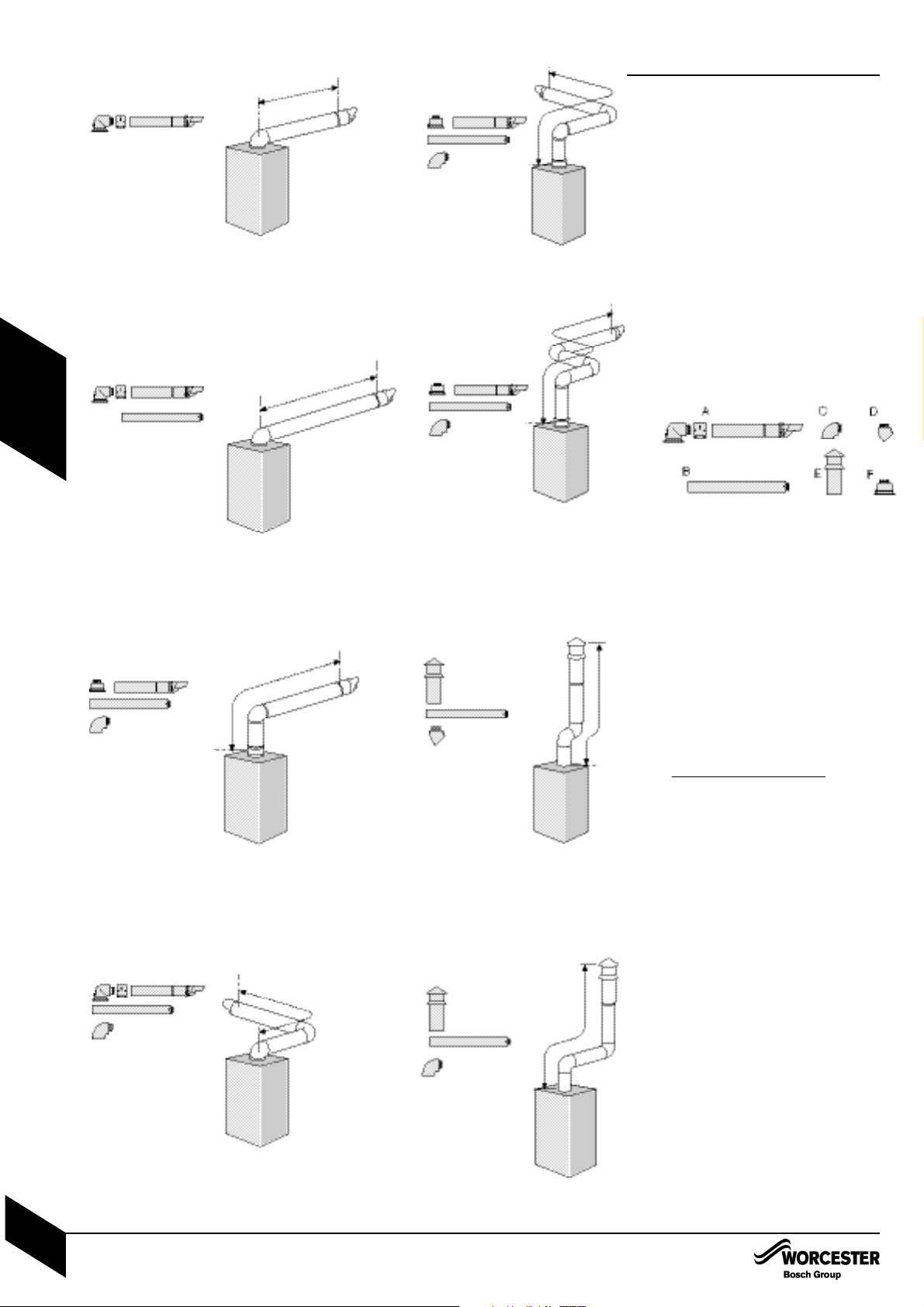
• The diagrams (opposite) show the
components used and the maximum flue
length for each configuration of 100mm and
125mm flues.
• Shaded flue components indicate the
standard 100mm horizontal flue.
• Only straight flue sections can be reduced in
length and cut.
• The flue terminal end can be fitted from the
inside or outside of the building.
• Fixing kits are supplied with the flue extension
kits.
• Horizontal 125mm and Vertical 100mm and
125mm flue kits are available with separate
instructions. Contact your supplier or
Worcester.
A - Standard horizontal flue (100mm diameter
shown)
B - Straight flue extension
C - Flue bend 90°
D - Flue bend 45°
E - Vertical terminal (vertical adaptor supplied
with terminal)
F - Vertical adaptor (used with horizontal
terminal)
Calculating the flue length:
Measure the total flue length required, noting
that the max
imum straight flue length including
the terminal is:
Horizontal 60/100mm: 4600mm
Horizontal 80/125mm: 13000mm
Vertical 60/100mm: 6400mm
Vertical 80/125mm: 15000mm
Then reduce the total straight flue length for
each extra flue bend (excluding the flue elbow)
by:
2000mm for 90°
1000mm for 45°
Flue Extension lengths:
Horizontal & Vertical 60/100mm: 960mm
Horizontal & Vertical 80/125mm: 1000mm
Flue Terminal lengths:
Horizontal 60/100mm: 800mm including terminal
Horizontal 80/125mm: 1200mm including terminal
Vertical 60/100mm: 1140mm to top of terminal
Vertical 80/125mm: 1365mm to top of terminal
STANDARD FLUE HORIZONTAL
Ø100
MAX 686 A x 1
MIN 250 A x 1*
Ø125
MAX 1070 A x 1
MIN 250 A x 1*
* Requires cutting
MAXIMUM FLUE HORIZONTAL
Ø100 - 4600mm
A x 1 + B x 5
Ø125 - 13000mm
A x 1 + B x 13
MAXIMUM FLUE VERTICAL START + 1 BEND
Ø100 - 4600mm
A x 1 + C x 1 + B x 5 +
Fx1
Ø125 - 13000mm
A x 1 + C x 1 + B x 13 +
Fx1
Ø100 - 2600mm
A x 1 + B x 3 + C x 1
Ø125 - 11000mm
A x 1 + B x 11 + C x 1
MAXIMUM FLUE HORIZONTAL + 1 BEND
MAXIMUM FLUE VERTICAL
START + 2 BEN DS
Ø100 - 2600mm
A x 1 + C x 2 + B x 4 +
Fx1
Ø125 - 11000mm
A x 1 + C x 2 + B x 13 +
Fx1
Ø100 - N/A
Ø125 - 9000mm
A x 1 + C x 3 + B x 11 +
Fx1
MAXIMUM FLUE VERTICAL
WITH 2 x 45° BENDS
Ø100 - 4400mm
(including terminal)
B x 5 + D x 2 + E x 1
Ø125 - 13000mm
(including terminal)
B x 13 + D X 2 + E x 1
Ø100 - 2400mm
(including terminal)
B x 4 + C x 2 + E x 1
Ø125 - 11000mm
(including terminal)
B x 13 + C x 2 + E x 1
VERTICAL FLUE WITH
2 x 90° BENDS
A
A
B
A
B
F
C
A
B
C
F
B
C
A
F
B
C
A
E
B
D
E
B
C
MAXIMUM FLUE VERTICAL
START + 3 BENDS
Page 19
IIMPORTANT: All the previous Pre-Installation sections must be read
and requirements met before starting boiler or flue installation.
E
F
A
B
C
C
D
G
UNPACKING WALL FRAME AND
ANCILLARY ITEMS
INSTALLATION & SERVICI NG INSTRUCTIONS FOR WORC ESTER GR EENSTAR 24 i junior/28 i junior
8 716 107 336b (11/05)
18
INSTALLATION
1
2
3
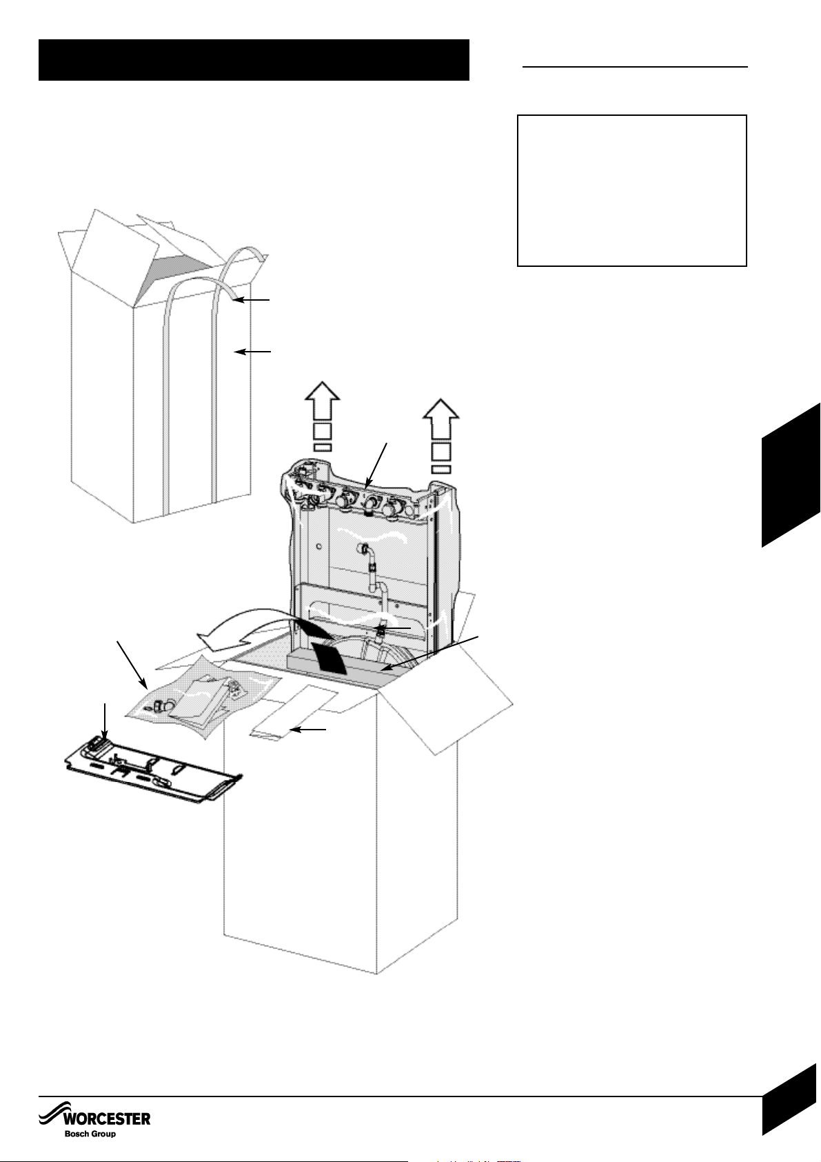
A - Straps
B - Outer carton
C - Installer pack
D - Bottom panel
E - Wall mounting frame
F - Wall template
G - Inner packaging
IMPORTANT HANDLING INSTRUCTIONS
• It is advised that two people are used to carry
the carton from the van to the point of delivery.
• Once the carton has been delivered, the outer
carton is removed first. Care should be taken
when releasing the straps. If a sharp implement
is used make sure the outer carton is not
pierced and that the implement is used in such
a way so that it may not cause personal injury.
All sharp objects must be covered or the blade
retracted after use and put away in a safe
place. The wall mounting frame, Installer
pack, template and bottom panel are now
removed. Care should be taken when lifting the
boiler from the base and the proper technique
for safe lifting of any heavy object should be
strictly observed.
Additional requirements for roof space
installation:
• The boiler should be first unpacked before
ascending ladder to loft space.
• Two sets of steps should be used.
• Two people should share the lifting of the
boiler up to the loft hatch, where the boiler is
entered into the loft space tilted and slid on its
back into the loft.
Once the appliance is removed from its
packaging check the contents against the
packing list.
Before installing appliance ensure system has
been cleaned as explained on page 8.
1. Remove straps (A) and open the top of the
boiler packaging.
2. Remove template (F) and wall mounting
frame (E) from the packaging.
3. Remove boiler bottom panel (D) and
installer pack (C).
UNPACKING WALL FRAME AND
ANCILLARY ITEMS
LIFTING AND CARRYING PRECAUTIONS:
• Lift only a manageable weight, or ask for
help.
• When lifting or putting things down, bend
the knees, and keep the back straight
and feet apart.
• Do not lift and twist at the same time.
• Lift and carry objects close to the body
Page 20
WALL MOUNTING PLATE FLUE OPENING
INSTALLATION & SERVICI NG INSTRUCTIONS FOR WORC ESTER GR EENSTAR 24 i junior/28 i junior
8 716 107 336b (11/05)
19
INSTALLATIONCOMMISSIONING
SAFETY:
All relevant safety precautions must be undertaken.
Protective clothing, footwear, gloves and safety
goggles must be worn as appropriate.
FIXING THE MOUNTI NG FRAME:
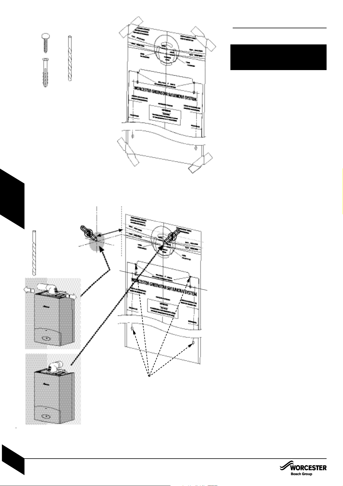
• The boiler template shows the relative
positions of the flue and the top and bottom
fixing of the mounting frame.
Fix the template to the wall in the desired
position (A).
Drill 4 holes for the wall mounting frame
through the template (2).
NOTE: The template has been sized to allow for
minimum clearances of 5mm sides, 200mm
base and 30mm above a Ø100mm flue elbow.
REAR FLUE OUTLET
• The drawing (B) opposite shows the boiler
template with the flue centre lines of both the
100mm and 125mm flue systems.
Mark centreline of flue to be used (1); the
external diameter of the hole can also be
marked if required.
• If a Ø100mm diameter flue is to be used,
a125mm diameter hole is required. However, if
using the weather sealing collar by pushing it
through from inside the property, then a
150mm diameter hole is required to
accommodate this.
• The terminal section of the 100mm flue has an
inbuilt 3° angle.
If extensions are to be added then the complete
flue must rise at an angle of 3°.
• The 125mm Ø flue system will require the flue
to rise at an angle of 3°.
Drill hole using a core drill or similar.
SIDE OUTLET:
Mark from the centre line of the wall template
to the wall which the flue will pass through (3).
Allow for a rise of 52mm per metre length of
flue, to give a 3° angle.
Clear any debris from the site.
• A pre-filling kit 7 716 192 282 is available for
installations where the boiler will not be fitted
immediately to the heating system. This allows
the heating system and mains water connections to be filled and checked prior to boiler
installation.
This kit can be used in conjunction with the
optional filling loop 7 716 192 281(not supplied with the boiler).
CAUTION: Ensure there are no pipes,
electric cables, damp proof courses or
other hazards before drilling.
WALL MOUNTING TEMPLATE
FLUE OPENING
189mm
2
A
B
X 4
X 4
USE APPROPRIATE
FIXINGS FOR
WEIGHT AND
WALL TYPE
Page 21
4
7
6
UNPACKING THE APPLIANCE
UNPACKING THE APPLIANCE
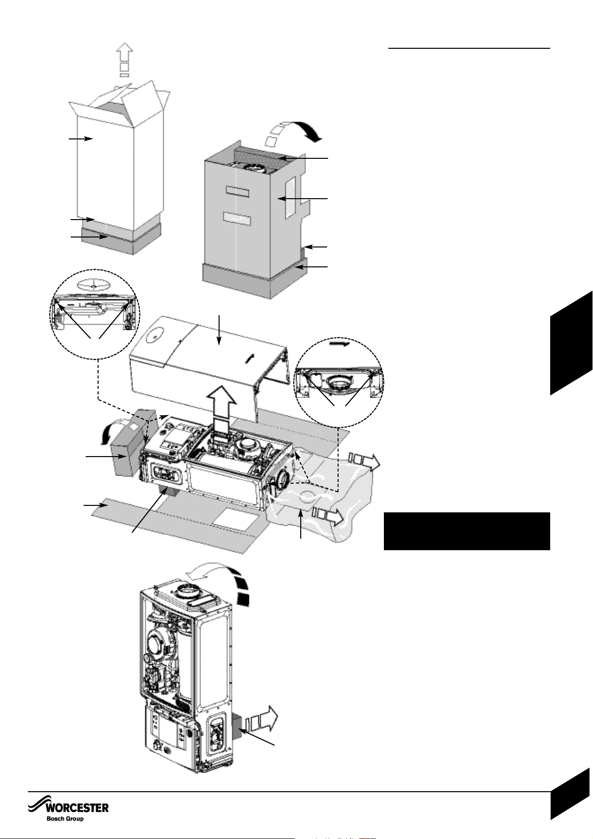
A - Outer carton
B - Inner sleeve (unwraps from front)
C - Packaging base
D - Protective wrapping
E - Appliance outer case
F - Protective inner packaging
4. Remove outer carton (A) and place
safely away from the working area.
5. With the outer packaging removed and
the inner sleeve (B) still in place gently
lay the boiler on its back.
6. The boiler will lie at an angle to the
floor to allow the boiler outer casing (E)
to be removed. The inner sleeve (B)
opens as shown. Remove the protective
wrapping (D) and undo the four screws,
two at the bottom of the boiler (H) and
two at the top (H) (see diagrams 6.1 and
6.2). Remove any packaging within the
boiler and the packaging base (C).
7. Stand boiler upright and remove the
protective inner packaging (F) at the rear
of the boiler.
UNPACKING THE APPLIANCE
INSTALLATION & SERVICI NG INSTRUCTIONS FOR WORC ESTER GR EENSTAR 24 i junior/28 i junior
8 716 107 336b (11/05)
20
INSTALLATION
A
5
B
C
F
B
C
F
H
H
B
C
D
E
F
F
6.1
6.2
CAUTION: Caps fitted to pipes must be
removed before hanging the boiler.
Page 22
A
E
D
B
BOILER CONNECTIONS
INSTALLATION & SERVICI NG INSTRUCTIONS FOR WORC ESTER GR EENSTAR 24 i junior/28 i junior
8 716 107 336b (11/05)
21
INSTALLATION
Handling
Hole
Do not lift by the
air gas manifold.
3
C
1A
22mm 15mm 22mm 15mm 22mm
2 & 4
H
1
BOILER CONNECTIONS
CAUTION: ISOLATE THE MAINS GAS
SUPPLY BEFORE STARTING ANY WORK
AND OBSERVE ALL R ELEVANT SAFETY
PRECAUTIONS.
4
2
Stop in
locked
position
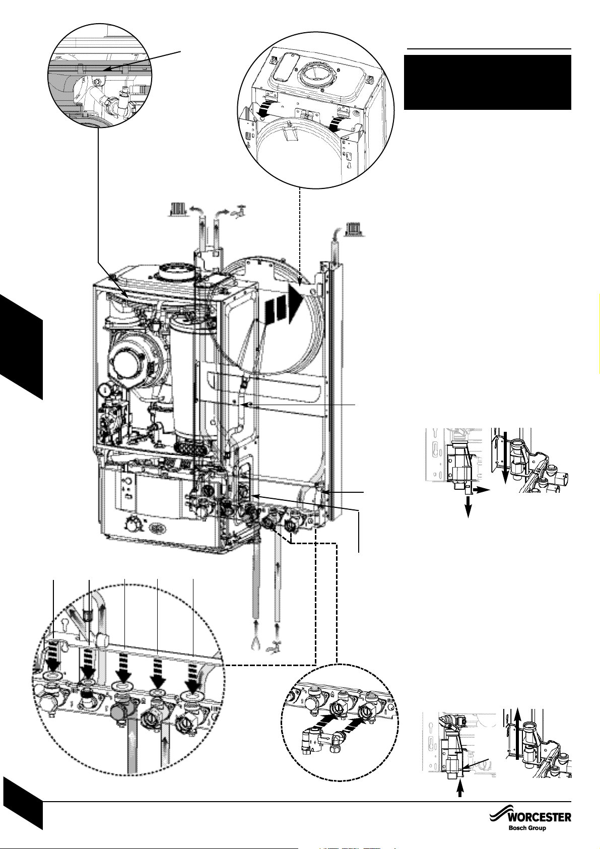
GAS AND WATER CONNECTIONS:
Remove template and secure the wall
mounting frame to the wall with the fixings
supplied.
System pipes may be run vertically upwards
behind the boiler or below it. See
Plumbing Manifold Section on page 15.
A - CH flow (22mm), B - CH return (22mm),
C - Gas inlet (22mm), D - Mains water inlet
(15mm), E - DHW outlet (15mm)
1. If using the optional filling loop 7 716 192
281 (not supplied with the boiler) fit it
before hanging the boiler on the wall frame.
1A. Fit sealing washers to service valves
before hanging boiler.
NOTE: The bonded washer supplied is for the
Gas connection only.
IMPORTANT:
Before hanging the boiler onto the wall
mounting frame ensure that the pressure relief
valve connection is in the DOWN position. This
is located on the right hand side of the wall
frame at the rear.
2. Pull the extended tab/lever forward and
down until there is no further travel.
3. Hang the boiler on to the wall mounting
frame by the two brackets positioned left
and right at the top rear of the appliance.
Do not lift the appliance by the air gas
manifold. There are two handling holes
incorporated into the inner casing left and
right in the lower section of the appliance.
IMPORTANT:
The pressure relief connector must be
repositioned after the boiler has been correctly
mounted to the wall mounting frame.
4. Push the lever on the pressure relief
connector UP until the stop on the inside of
the handle is over the shoulder of the metal
bracket to secure in place.
Page 23
BOILER CONNECTIONS
INSTALLATION & SERVICI NG INSTRUCTIONS FOR WORC ESTER GR EENSTAR 24 i junior/28 i junior
8 716 107 336b (11/05)
22
INSTALLATION
BOILER CONNECTIONS
CAUTION: ISOLATE THE MAINS GAS
SUPPLY BEFORE STARTING ANY WORK
AND OBSERVE ALL R ELEVANT SAFETY
PRECAUTIONS.
A
E
D
B
C
22mm 15mm 22mm 15mm 22mm
5
F
H
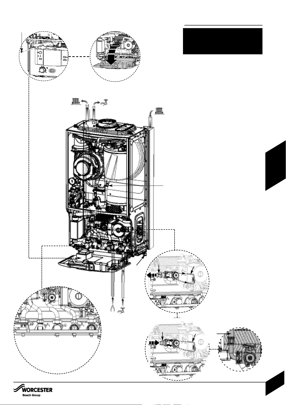
GAS AND WATER CONNECTIONS:
A - CH flow (22mm), B - CH return (22mm),
C - Gas inlet (22mm), D - Mains water inlet
(15mm), E - DHW outlet (15mm)
5. Lower the control panel into the service
position by removing the screw (F) from the
retaining bracket.
6. Make connections to the heating system.
Connect the gas supply to the boiler gas
cock 22mm compression.
Connect mains water in and DHW out.
7. Connect the expansion vessel flexible
pipe to the hydraulic manifold situated left of
the pump. It is necessary to remove and
discard the gray plastic blanking plug (G)
from the pressure vessel connection at the
hydraulic manifold before securing the
expansion vessel flexible pipe (H) in place
with the wire retaining clip ( I ) .
8. Connect the pressure relief drain pipe to
15mm compression joint (J) using the
compression nut and olive supplied in the
hardware literature pack.
6
7
G
I
I
H
H
J
A E C D B
Page 24
FLUE INSTALLATION
INSTALLATION & SERVICI NG INSTRUCTIONS FOR WORC ESTER GR EENSTAR 24 i junior/28 i junior
8 716 107 336b (11/05)
23
INSTALLATION
FLUE INSTALLATION
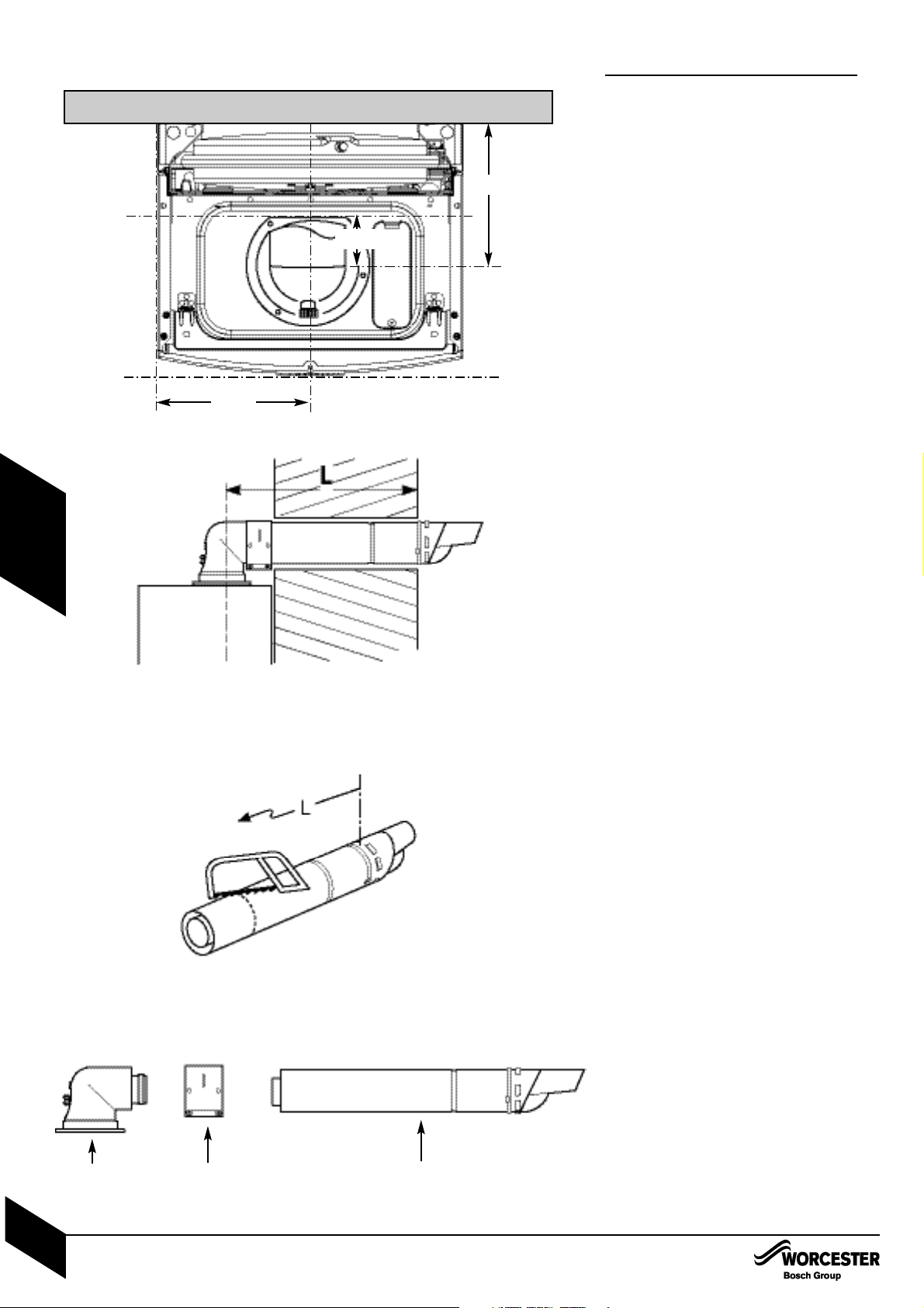
HORIZONTAL FLUE
(60/100mm diameter)
For vertical flues and 80/125mm horizontal flues,
please refer to separate instructions supplied with
the flue kit.
NOTE: to ease the assembly of flue components,
apply silicone lubricant to sealing surfaces.
The instructions for the 60/100mm diameter flue
are shown below.
MEASURING THE FLUE (Standard Flue):
Measure from the outside wall to the centre
line of the flue turret.
Subtract 93mm from the length L to give
the correct dimension to the flue elbow
connection.
The terminal section should be cut to this
dimension, however it must not be cut
shorter than 250mm.
After cutting, the end must be square and
free from burrs to prevent damage to the
flue seals.
Edge of
case
200mm
WALL
189mm
93mm
(250mm min)
FlueClampTurret
Page 25
FLUE INSTALLATION
INSTALLATION & SERVICI NG INSTRUCTIONS FOR WORC ESTER GR EENSTAR 24 i junior/28 i junior
8 716 107 336b (11/05)
24
INSTALLATION
FLUE INSTALLATION
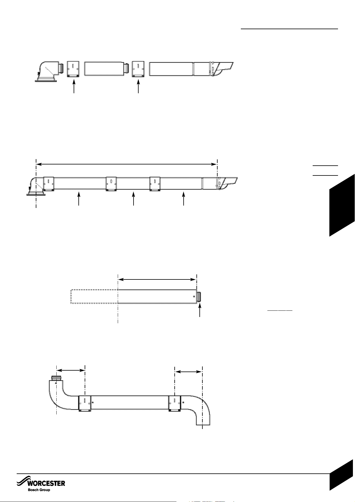
MEASURING THE FLUE (Extension Flue Kits):
ONLY CUT EXTENDED FLUE LENGTHS
As with the Standard Flue measure from the
outside wall to the centre line of the flue
turret.
Subtract the length of the Standard Flue
and turret (725mm) from length L .
Subtract the full length 1m extension(s)
from the figure.
Cut one of the 1m extensions to the remainder.
Cut both tubes square taking care not to distort
the tubes.
Remove any burrs.
EXAMPLE:
Length L = 2380mm
Subtract Standard Flue+Turret — 686mm
Subtract Full Extension — 960mm
Cut Length = 734mm
NOTE: The minimum length a flue extension
can be cut to is 100mm
NOTE: Where extensions are reduced, cut
length which DOES NOT contain the seal.
ADDITION OF FLUE BENDS:
When flue bends are being used an allowance
of 98mm per bend must be allowed from the
centre line of the bend. In the example shown
using a flue extension with 2 bends will
achieve a total length of 1148mm.
Clamp
Clamp
Extension
734mm
Cut Length
Standard Flue
Seal
2380mm
Required Length
94mm
94mm
Page 26
FLUE INSTALLATION
INSTALLATION & SERVICI NG INSTRUCTIONS FOR WORC ESTER GR EENSTAR 24 i junior/28 i junior
8 716 107 336b (11/05)
25
INSTALLATION
A
B
C
D
E
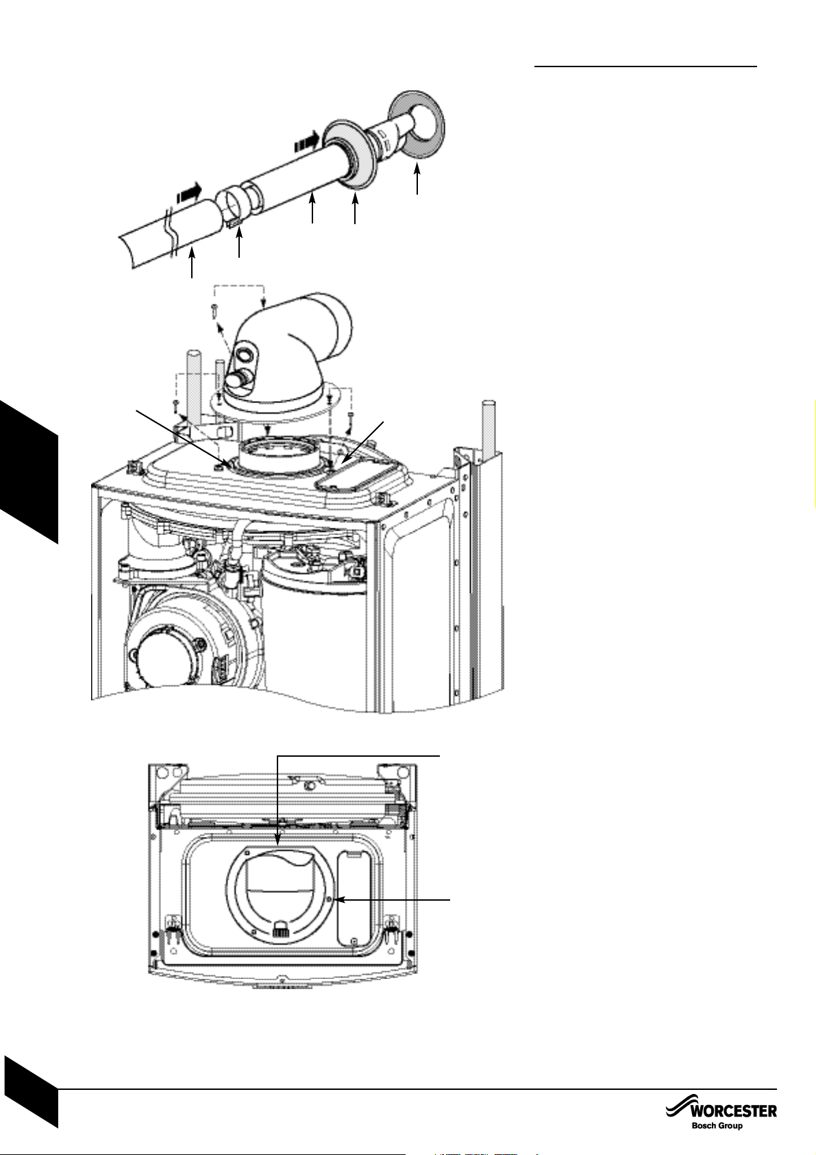
A - Standard Flue
B - Internal Wall Seal
C - External Wall Seal
D - Clamp
E - Extension Duct
Flat at back
FLUE INSTALLATION
ASSEMBLING THE FLUE
1 Slide inner collar (B) onto terminal (A)
2 Additional extensions or bends:
Push fit all extensions/bends/terminal
together and secure connections with
clamps (D). The slope of the terminal outlet
must face downwards.
FITTING THE FLUE
3 Fit the terminal (A) through the flue opening
in the wall, exposing the plastic outlet
section to the outside and fit the outer
flue collar ( C ) over the notches to secure.
4 Assemble elbow to boiler using the three
screws (see below).
Note: Screws are in boiler not in flue kit.
FITTING THE ELBOW:
• Flue elbow should push directly down and
not be twisted into correct position.
Remove the 3 inner flue tube retaining
screws. The inner tube will be held in place
in the appliance.
Fit turret onto appliance and retain with the
three removed screws.
NOTE: The clamping plate flat should be at
the rear of the appliance.
ADDITIONAL NOTES AND REMINDERS:
• Ensure that all cut lengths are square and
free from burrs.
• The flue, when assembled, is fully sealed and
components are pushed home.
• The flue is set at an angle of 3° or 52mm per
1m length.
This screw should
be fitted last for
rear exit
This screw should
be fitted last for
easier installation
Apply silicone
grease to seal
Page 27
CONDENSATE CONNECTION:
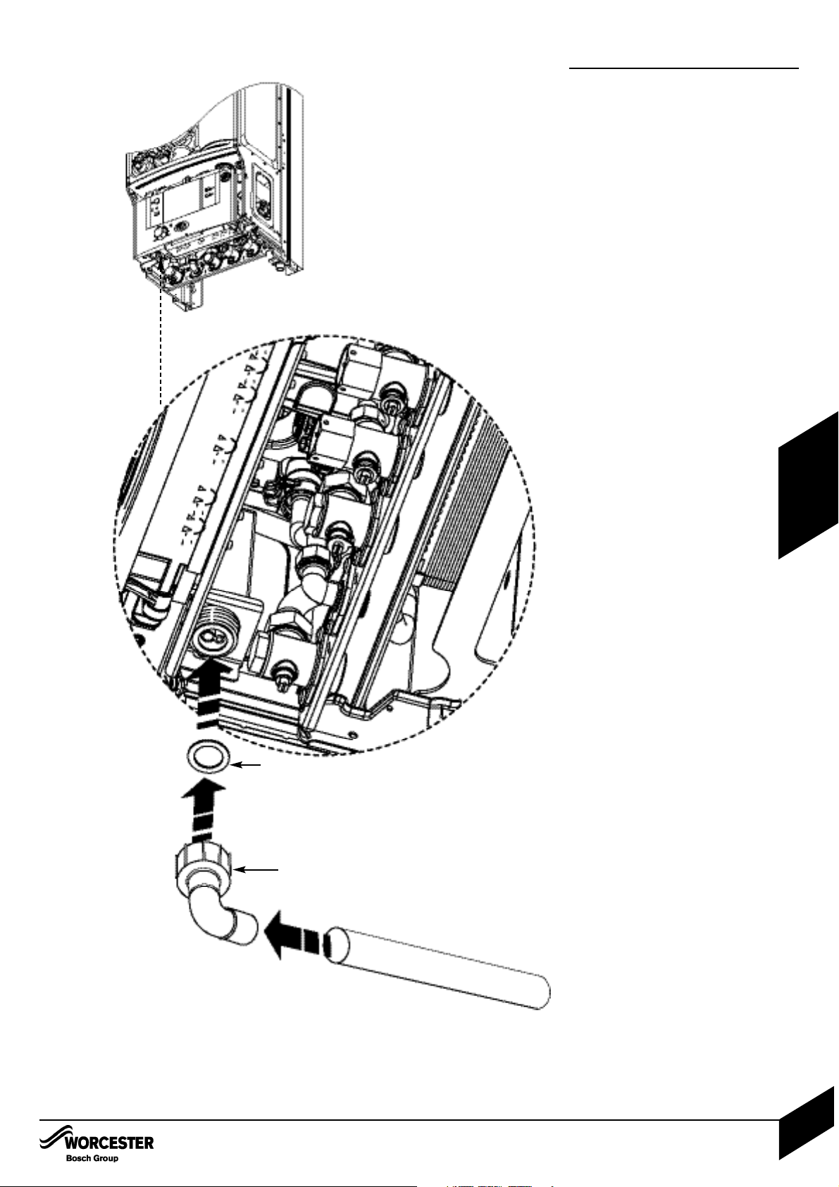
Never terminate or discharge into any open
source, including; sink, bath, shower, bidet,
toilet etc.
Note: any external condensate pipework
should be protected with weather resistant
insulation to help prevent freezing.
• Ensure that the condensate drain is 22mm
diameter plastic pipe. It must fall at least
50mm per metre towards the outlet.
• An adapter in 22mm pipe is contained in the
fitting pack (A) along with sealing washer (B).
CONDENSATE CONNECTION
A
B
CONDENSATE CONNECTION
INSTALLATION & SERVICI NG INSTRUCTIONS FOR WORC ESTER GR EENSTAR 24 i junior/28 i junior
8 716 107 336b (11/05)
26
INSTALLATION
Page 28
ELECTRICS
A
1
2
B
ELECTRICS
INSTALLATION & SERVICI NG INSTRUCTIONS FOR WORC ESTER GR EENSTAR 24 i junior/28 i junior
8 716 107 336b (11/05)
27
INSTALLATION
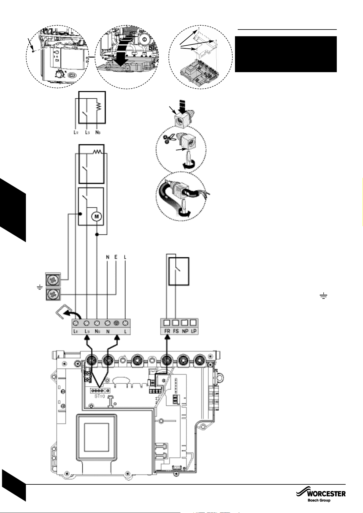
CAUTION: ISOLATE THE MAINS
ELECTRICITY SUPPLY BEFORE STARTING
ANY WORK AND OBSERVE ALL
RELEVANT SAFETY PRECAUTIONS
Mains supply to the boiler must be through a
fused double pole isolator situated adjacent
to the appliance. The isolator must have a
contact separation of 3mm minimum in all
poles. External fuse rating 3A.
When stripping wires always ensure copper
strands do not fall into the control box.
Access to electrical connections:
Remove boiler casing to access control panel.
1 Unscrew screw (A) and lower the control
box into the horizontal position.
2 Unscrew the three screws (B) in the control
panel and pull off the connections cover.
3 Unclip cable clamp (C).
4 Cut off the tapered cable entry to fit cable
diameter required.
5 Turn cable retaining screw (D) anti-clockwise.
Run cable over the main crossbar and
through the cable clamp (C), ensuring there
is ample cable to reach the connectors.
Turn cable clamping screw (D) clockwise to
secure cable.
After wiring to connectors is complete, snap
cable clamp (C) into control box.
6 Mains power 230v connection (ST10):
Separate wires from cable end and
strip to 6mm
Connect LIVE wire to terminal (L)
Connect NEUTRAL wire to the terminal (N)
Connect EARTH wire to the bracket
NOTE: Earth cable to be longer so that it pulls
out last if mains cable is snagged.
7 230V room stat/clock (ST10):
The diagram shows the option of roomstat with
programmer or roomstat only.
Remove link.
Connect LIVE supply to terminal (L
S).
Connect SWITCHED LIVE to terminal (LR),
NOTE: This is sometimes refered to as ‘call for
heat’ or ‘heating load’.
Connect NEUTRAL to terminal (NS).
NOTE: Some devices do not require this.
8 Optional external frost stat connection (ST6):
Connect froststat cables to terminals (FS) and
(FR). These are not polarity sensitive.
9 Refit panels.
3
C
4
5
D
6
7
8
F1
F3
F2
ROOMSTAT
ONLY
PROGRAMMER
ROOMSTAT
AND
PROGRAMMER
ROOMSTAT
230V
MAINS
SUPPLY
ST6ST10
earth
switched live
live
neutral
blue
green/yellow
brown
FROSTSTAT
Page 29
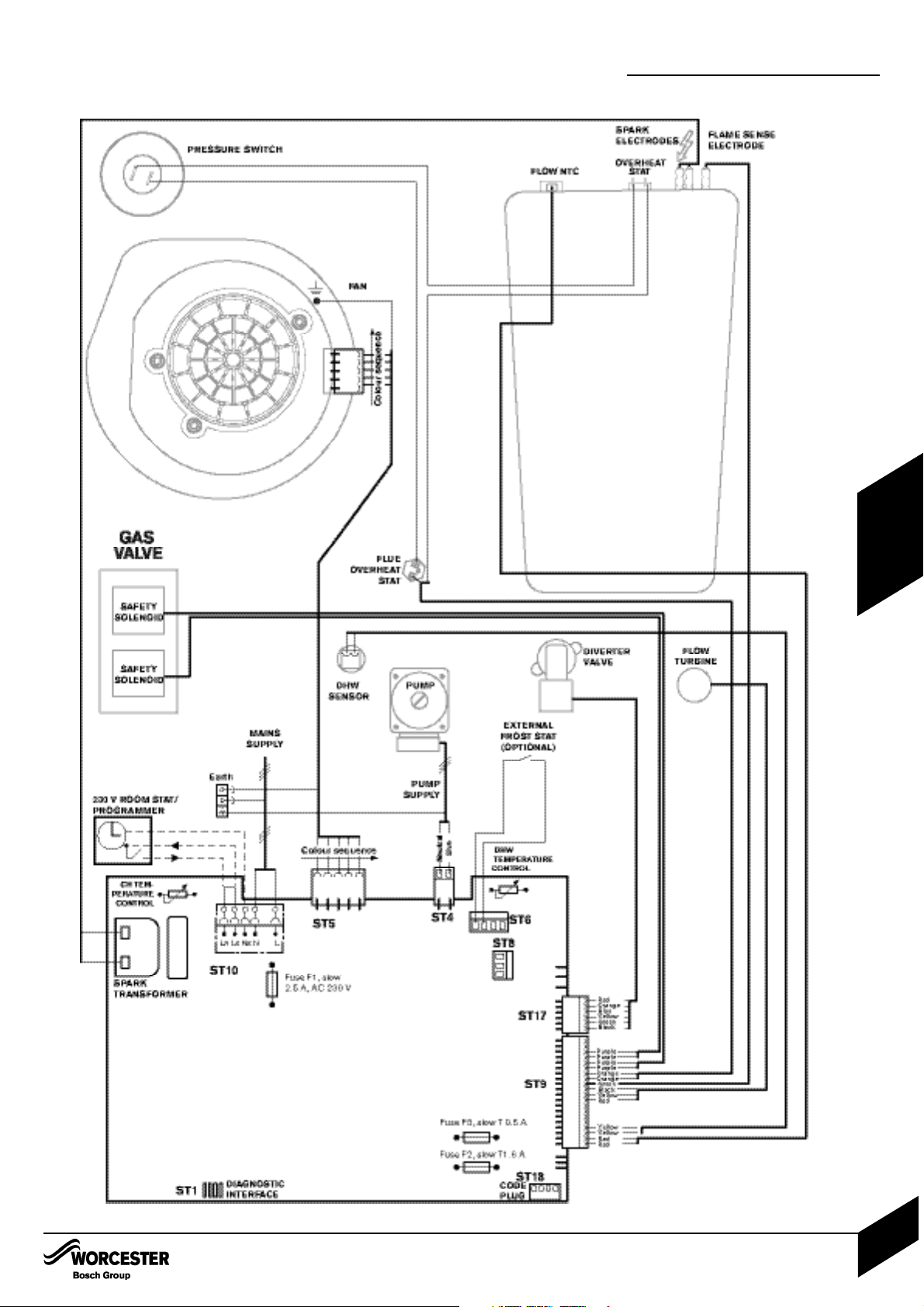
POSITION OF WIRED
COMPONENTS
COMMISSIONING
POSITION OF WIRED COMPONENTS
INSTALLATION & SERVICI NG INSTRUCTIONS FOR WORC ESTER GR EENSTAR 24 i junior/28 i junior
8 716 107 336b (11/05)
28
INSTALLATION
Page 30
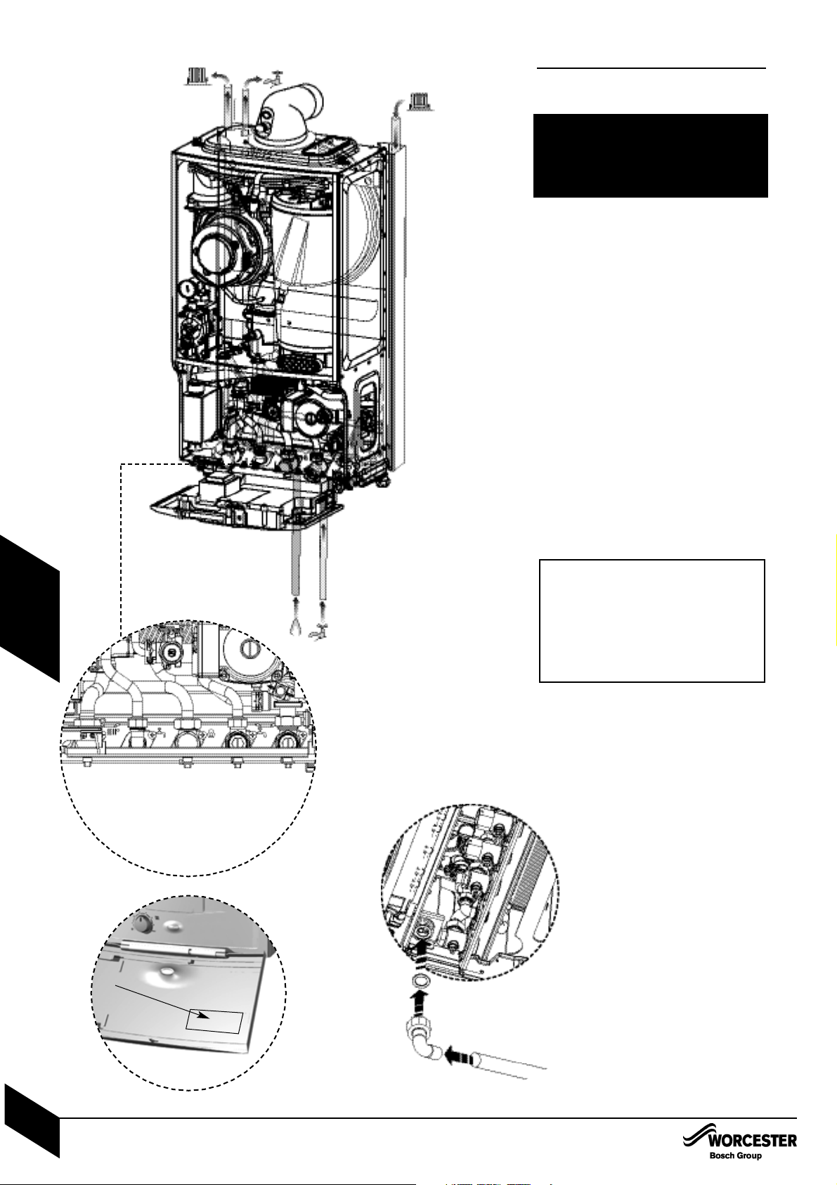
PRE-COMMISSIONING CHECKS
INSTALLATION & SERVICI NG INSTRUCTIONS FOR WORC ESTER GR EENSTAR 24 i junior/28 i junior
8 716 107 336b (11/05)
29
COMMISSIONING
A
E
B
C
D
22mm 15mm 22mm 15mm 22mm
1
2
3
F
J
PRE-COMMISSIONING
CHECKS
CAUTION: ISOLATE THE MAINS
SUPPLIES BEFORE STARTING ANY
WORK AND OBSERVE ALL
RELEVANT SAFETY PRECAUTIONS
1 Check that the service and water pipes are
connected to the correct position on the
manifold.
A - CH Flow (22mm)
B - CH Return (22mm)
C - Gas inlet (22mm)
D - DHW (15mm)
E - Water in (15mm)
2 Check the gas type specified on the
identification plate (F) matches that of the
gas supply. Turn on the main gas supply,
check the gas pipework, connections and
rectify any leaks.
3 Check that the condensate pipe has been
connected to the syphon.
4 Check pressure relief drain pipe (J) is
correctly fitted and securely tightened.
IMPORTANT: If the boiler is not to be
commissioned immediately then:
after successfully completing all of the
checks and any rectification work,
close the gas and water valves, shut off
the gas supply and electrically isolate
the boiler and label appropriately.
A D C E B
Page 31
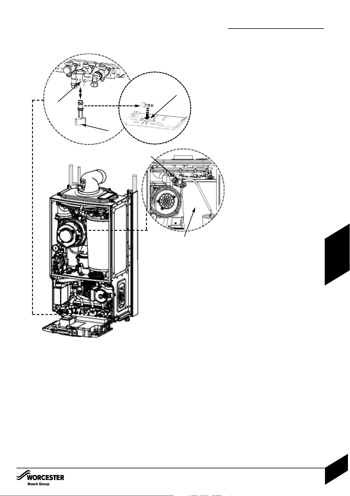
FILLING THE SYSTEM
INSTALLATION & SERVICI NG INSTRUCTIONS FOR WORC ESTER GR EENSTAR 24 i junior/28 i junior
8 716 107 336b (11/05)
30
COMMISSIONING
FILLING THE SYSTEM
1 Turn on the water main and open the
system valves.
2 Open all radiator valves.
3 Fill the system via a WRAS approved filling
loop to 1 bar then turn the valve anti-clock-
wise to close.
4 Vent (A) any air from the boiler heat
exchanger using a suitable container to
collect any water. Ensure tube outlet (B) is
directed away from the fan or any other
electrical component to prevent any water
damage. Also place a suitable cover over
the fan to prevent any spillage of water
on to electrical connections. Ensure the
cover is removed after venting.
5 Vent all radiators, retighten when completed
and check the system and correct any leaks.
• The boiler integral expansion vessel is pre-
charged to 0.75 bar (equal to a static head
of 7.5m (22ft). A Schraeder type valve is
fitted to the expansion vessel to allow for
pressure adjustment if required.
• If an extra expansion vessel is fitted to the
central heating return, adjust this to the
same pressure as the appliance internal
expansion vessel, refer to separate instructions with the extra expansion vessel.
6 Briefly open the pressure relief valve to test
its operation.
7 If required increase system pressure back to
1 bar.
8 Rotate the adjustable pointer on the
pressure gauge to record the set system
pressure.
9 Isolate and remove filling loop connection to
system or if using the optional integral filling
connection (C) (not supplied with the
boiler) remove key (D) and place in
its storage position (E) on the bottom cover
of the boiler.
• A pre-filling kit 7 716 192 282 is available for
installations where the boiler will not be fitted
immediately to the heating system. This
allows the heating system and mains water
connections to be filled and checked prior to
boiler installation.
This kit can be used in conjunction with the
optional filling loop 7 716 192 281(not supplied with the boiler).
A
B
C
D
E
Page 32
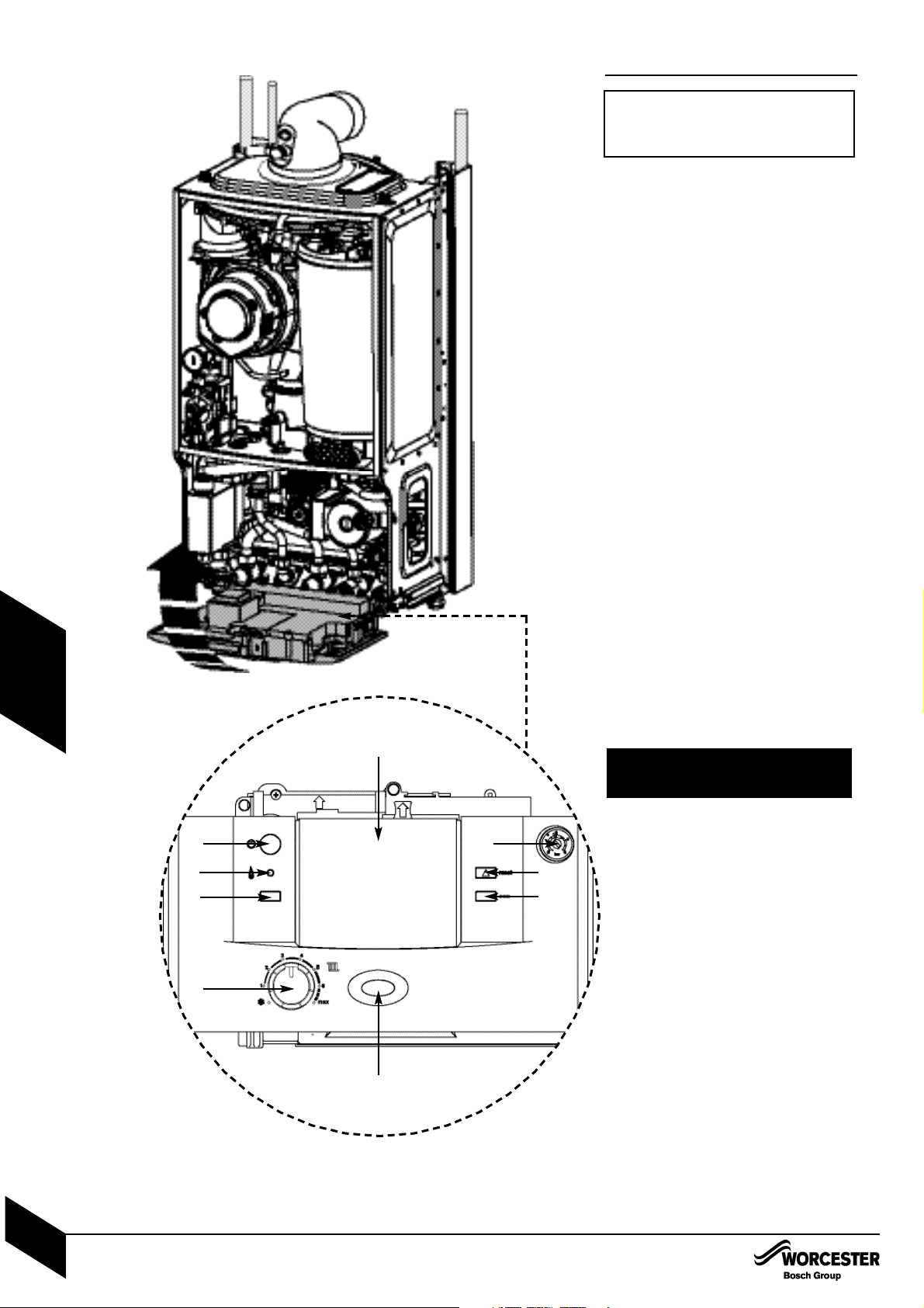
A
D
F
C
B
G
E
H
I
Switching the appliance on/off:
1 Turn on mains power supply
Turn on any external controls
Set the thermostatic radiator controls to
maximum temperature
Set the clock/programmer to continuously
ON and the room thermostat to maximum
temperature
2 A - On/off button
B - On/off and fault indicator (BLUE)
C - Central heating temperature control
D - Burner indicator (GREEN)
E - Reset button
F - Service button
G - ECO button
H - System pressure gauge
I - Cover or optional programmer
Press power button (A) and the power
on indicator (B) illuminates BLUE.
3 Turn the boiler thermostat control (C) to
maximum. The burner on indicator (D)
illuminates GREEN when the burner
has lit.
4 If the boiler fails to light the B LUE power
indicator (B) and reset button (E) will
flash alternately.
To reset press and hold the reset button
(E) for 2 seconds. The boiler will be
reset.
STARTING THE APPLIANCE
IMPORTANT: Never run the appliance
when the appliance/system is empty or
partially filled.
CAUTION: DO NOT PRESS POWER
INDICATOR (B) TO RESET BOILER.
STARTING THE APPLIANCE
INSTALLATION & SERVICI NG INSTRUCTIONS FOR WORC ESTER GR EENSTAR 24 i junior/28 i junior
8 716 107 336b (11/05)
31
COMMISSIONING
Page 33
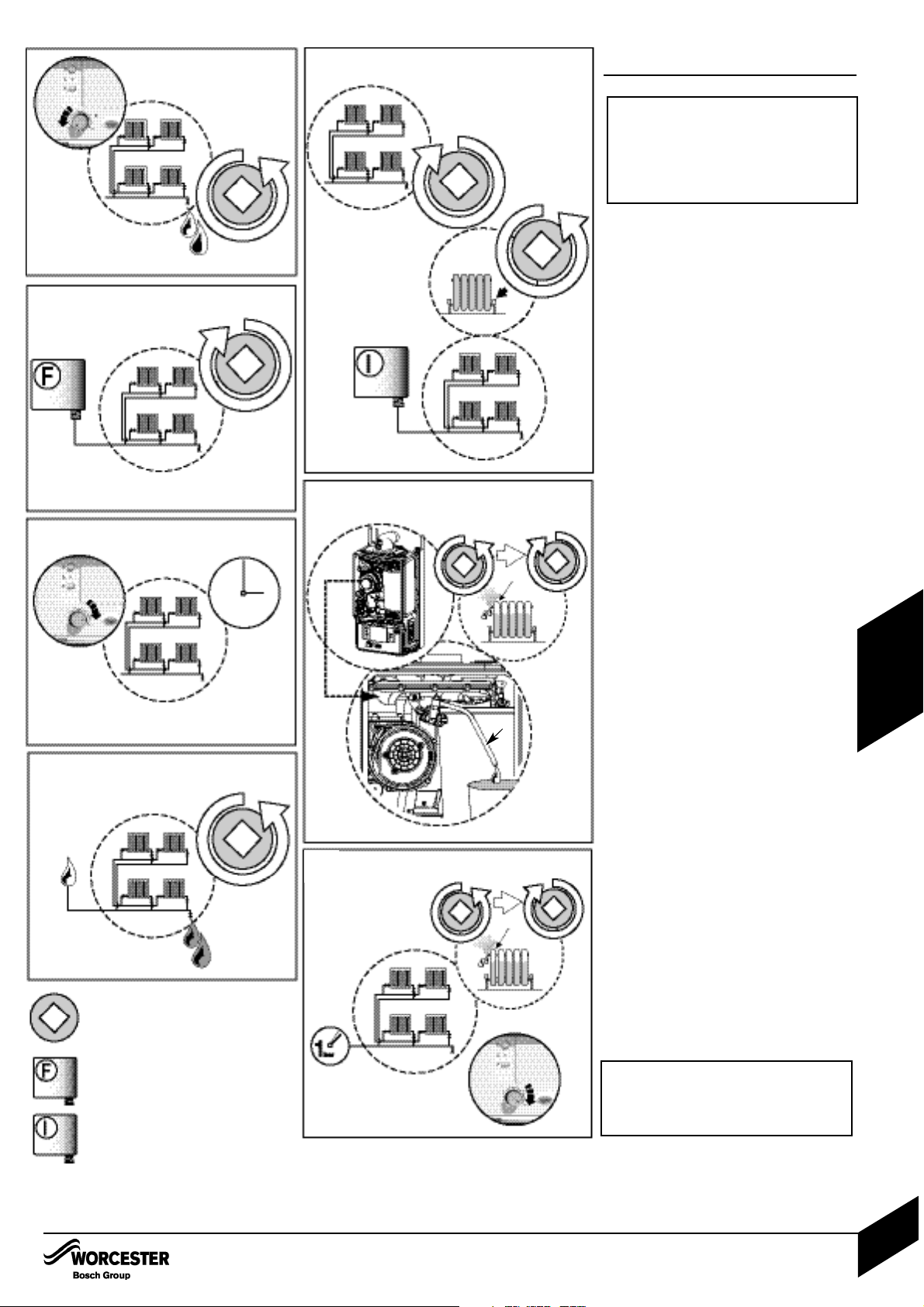
WATER TREATMENT
ENSURE THAT THE SYSTEM HAS BEEN
CLEANED AS ON PAGE 8 OF THESE
INSTRUCTIONS.
FLUSHING (Central Heating):
1 Switch off the boiler (A).
Open all drain cocks (B) and drain the
system (C) while the appliance is hot.
2 Close drain cocks (D) and add a suitable
flushing agent (E) at the correct strength for
the system condition in accordance with the
manufacturer's instructions.
3 Run the boiler/system at normal operating
temperature (F) for the time stated by the
manufacturer of the flushing agent (G).
4 Drain (H) and thoroughly flush the system to
remove the flushing agent and debris ( I ).
INHIBITOR (Central Heating):
5 Check drain cocks are closed ( J ) and all
radiator valves are open (K) before adding a
suitable*inhibitor (or combined inhibitor/antifreeze if the system is exposed to freezing
conditions) to the heating system water (L) in
accordance with the manufacturers instructions.
6 Fill system via a WRAS approved filling loop
to between 1 and 2 bar.
7 Vent all radiators; retighten vents when
complete (M). Vent any air from the boiler
heat exchanger using a suitable container to
collect any water (N).
Ensure tube outlet (O) is directed away
from the fan or any other electrical
component to prevent damage. Also
place a suitable cover over the fan to
prevent any spillage of water onto
electrical connections. Ensure the cover
is removed after venting.
8 Vent all radiators (P).
Re-pressurise if necessary to 1bar (Q).
Set all controls to maximum (R).
Record the date when the inhibitor was
added to the system on the guarantee card.
NOTE: The concentration level of inhibitor in
the system should be checked every 12
months, or sooner if system content is lost.
The addition of sealing agents to the system
water is not recommended as this can cause
problems with deposits left in the heat exchanger.
IMPORTANT: Debris from the system
can damage the boiler and reduce
efficiency. Failure to comply with the
guidelines for the use of water
treatment with the appliance will
invalidate the appliance warranty.
* compatible with aluminium. The pH
value of the system water must be
less than 8 or the appliance guarantee
will be invalidated.
1
2
3
4
5
7
8
A
B
C
D
E
F
G
H
I
J
J
K
L
M
N
O
P
Q
R
KEY
Valve
Flushing
Agent
Inhibitor
WATER TREATMENT
INSTALLATION & SERVICI NG INSTRUCTIONS FOR WORC ESTER GR EENSTAR 24 i junior/28 i junior
8 716 107 336b (11/05)
32
COMMISSIONING
Page 34
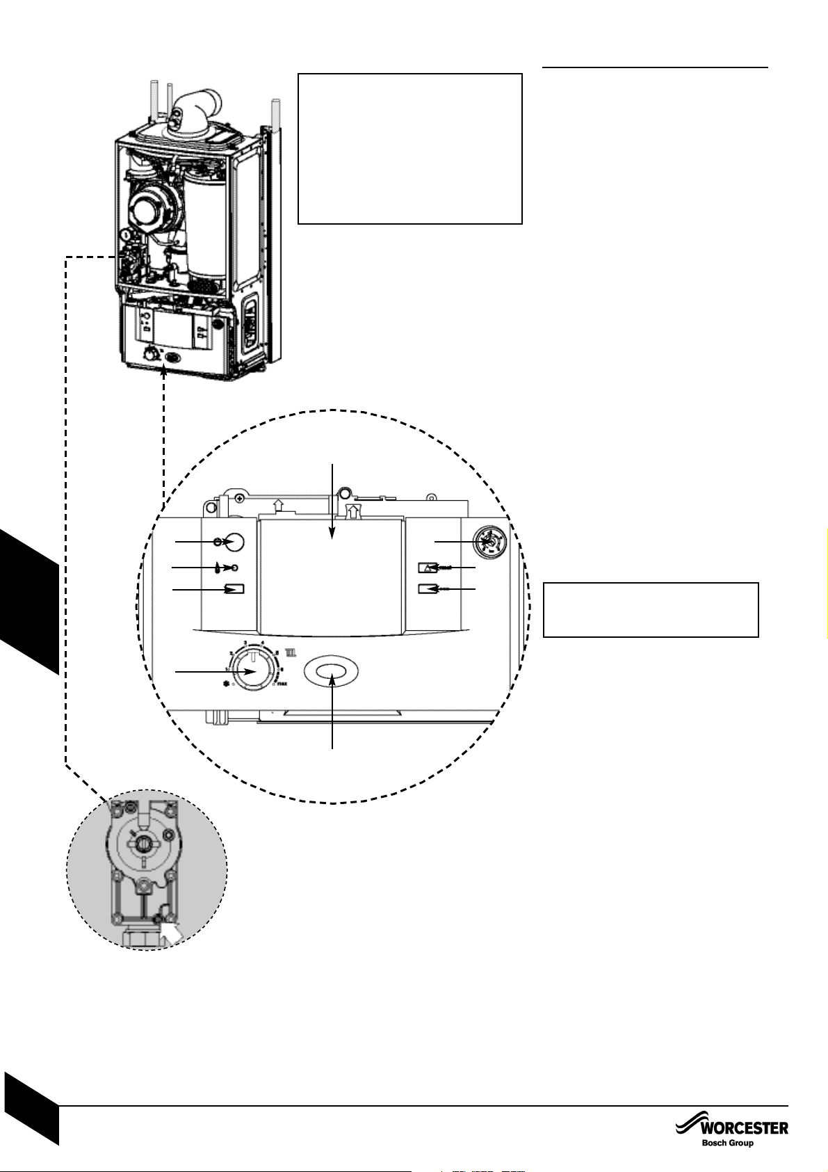
COMMISSIONING
THE COMBUSTION FOR THE APPLIANCE
IS FACTORY SET.
NO ADJUSTMENT IS REQUIRED IF THE
GAS INLET PRESSURE IS CORRECT.
CHECKING GAS INLET PRESSURE:
The inlet pressure to the appliance must be
checked using the following procedure:
SETTING THE BOILER TO MAXIMUM:
1 Press service button (F) for 10 seconds and
set Central Heating temperature to maximum.
• The service button will illuminate continually
and the blue power indicator will flash quickly.
MEASURING THE INLET PRESSURE:
2 Slacken the screw in the inlet pressure test
point and connect a manometer.
Measure the pressure with the boiler
running at maximum.
Check the gas supply working pressure at
the gas valve inlet point is not less than:
N.G. 18.5 mbar
L.P.G. 37 mbar
The gas rate should be measured at the
gas meter after 10 minutes operation at
maximum. See technical data section at the
front of this manual.
Ensure inlet pressure is satisfactory with all
other gas appliances working.
Replace controls cover. NOTE: This boiler is
designed with a differential of 20°C across
the heating system.
If pressure is satisfactory press the
service button (F) again and the boiler
will return to normal operation.
• If left in the service mode the control will
return to normal operation after 15 minutes.
Re-seal the screw in the gas inlet pressure
test point.
DOMESTIC HOT WATER:
Controlling the hot water temperature
The hot water temperature is fixed at 55°C.
DOMESTIC HOT WATER PRE-HEAT:
Pre-heat reduces the time taken to produce hot
water at the tap and is controlled by the ECO
button (H).
Press the ECO button to select either:
When the ECO button is not illuminated the
boiler will be in pre-heat mode (which will
reduce the time taken to produce hot water at
the tap).
OR
When the ECO button is illuminated the boiler
will be in economy mode with pre-heat no
longer active.
IMPORTANT: Do not continue
commissioning until the correct
gas pressure is achieved.
Inlet Test Nipple
A
D
F
C
B
G
E
H
I
A - On/off button
B - On/off and fault indicator (BLUE)
C - Central heating temperature control
D - Burner indicator (GREEN)
E - Reset button
F - Service button
G - ECO button
H - System pressure gauge
I - Cover or optional programmer
NOTE: When running in the service
mode, the boiler will operate both
the central heating and the domestic
hot water circuits. This is to allow
sufficient time for this part of the
commissioning procedure. It will be
necessary to run water through the
domestic hot water circuit to ensure
that the boiler will not cycle on low
heating demands.
COMMISSIONING
INSTALLATION & SERVICI NG INSTRUCTIONS FOR WORC ESTER GR EENSTAR 24 i junior/28 i junior
8 716 107 336b (11/05)
33
COMMISSIONING
Page 35
FINISHING COMMISSIONING
INSTALLATION & SERVICI NG INSTRUCTIONS FOR WORC ESTER GR EENSTAR 24 i junior/28 i junior
8 716 107 336b (11/05)
34
COMMISSIONING
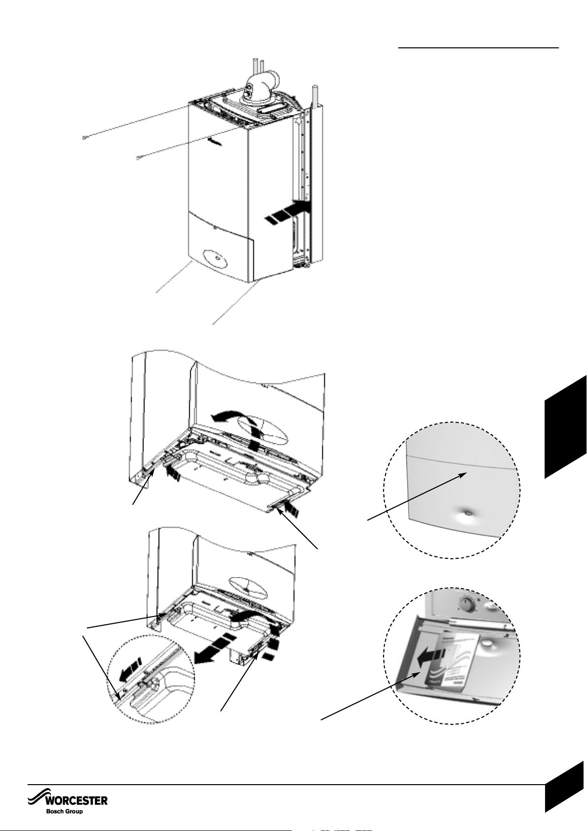
FINISHING COMMISSIONING
The boiler has been factory set, so there
should be no need to adjust any controls.
REPLACE OUTER CASING:
1 Replace outer casing making sure that the
securing points are properly located.
Replace top two screws (A).
Retighten bottom two screws (B).
INSTALLING BOTTOM PANEL:
2 The bottom panel slides onto two ledges
(C) either side of the boiler frame.
Hold the panel up against the underside of
the boiler and slide towards the rear until it
is fully engaged.
HANDOVER:
Complete the Benchmark checklist.
NOTE: The Benchmark Checklist can be
found at the rear of these instructions.
Open the facia cover by gently pressing the
centre top of the cover (D).
Set up the controls and show the user how
to operate all the controls shown in the User
Guide.
Place the user guide into the tray (E) on the
inside of the facia cover.
If the appliance is unused and exposed to
freezing conditions, shut off all the mains
supplies and drain the system and boiler.
A
A
B
B
C
A
C
C
C
D
E
Page 36
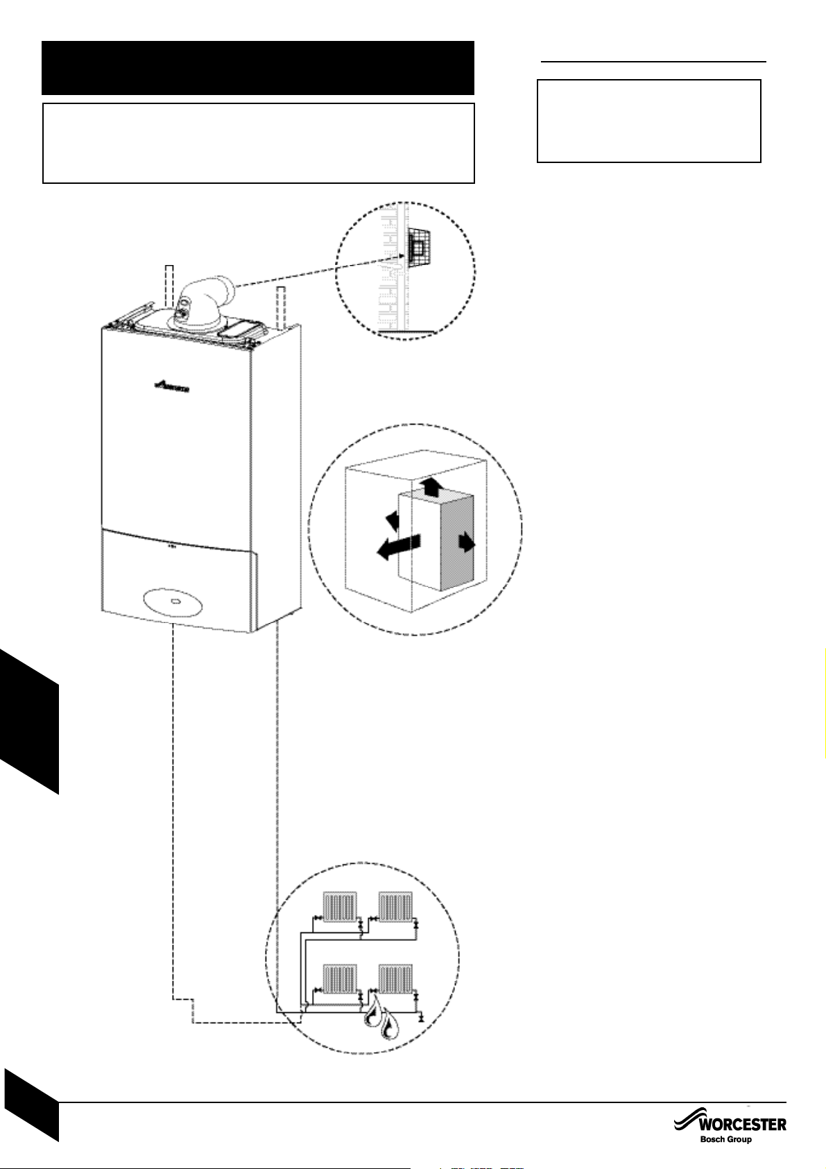
INSPECTION AND SERVICE
To ensure the continued efficient operation
of the appliance it must be checked at
regular intervals.
The frequency of servicing will depend upon
the particular installation conditions and
usage. However, an annual service is
recommended .
The extent of the service required by the
appliance is determined by the operating
condition of the appliance when tested by
fully qualified engineers.
The service interval record sheet at the rear
of these instructions must be completed
after each service.
Inspection
1 Check that the terminal and the terminal
guard, if fitted, are clear and undamaged.
2 If the appliance is in a compartment or
cupboard check that the specified service
space around the appliance is clear.
3 Check all the joints and connections in the
system and remake any that show signs of
leakage. Refill and re-pressurise if
applicable as described in Commissioning.
Operate the appliance and take note of any
irregularities.
Refer to Fault Finding for rectification
procedures.
IMPORTANT: Any service work
must be carried out by competent
registered engineers such as
British Gas or Corgi registered
personnel.
CAUTION: TURN OFF THE GAS SUPPLY AND ISOLATE THE MAINS
SUPPLIES BEFORE STARTING ANY WORK AND OBSERVE ALL
RELEVANT SAFETY PRECAUTIONS.
IMPORTANT: AFTER REPLACEMENT OF ANY COMPONENTS ALWAYS
CHECK FOR GAS SOUNDNESS WHERE RELEVANT AND CARRY OUT
FUNCTIONAL CHECKS AS DESCRIBED IN COMMISSIONING.
ANY O-RING OR GASKET THAT APPEARS DAMAGED MUST BE
REPLACED.
1
2
3
INSPECTION AND SERVICE
INSTALLATION & SERVICI NG INSTRUCTIONS FOR WORC ESTER GR EENSTAR 24 i junior/28 i junior
8 716 107 336b (11/05)
35
SERVICING
& SPARES
Page 37
INSPECTION AND SERVICE
Component Access
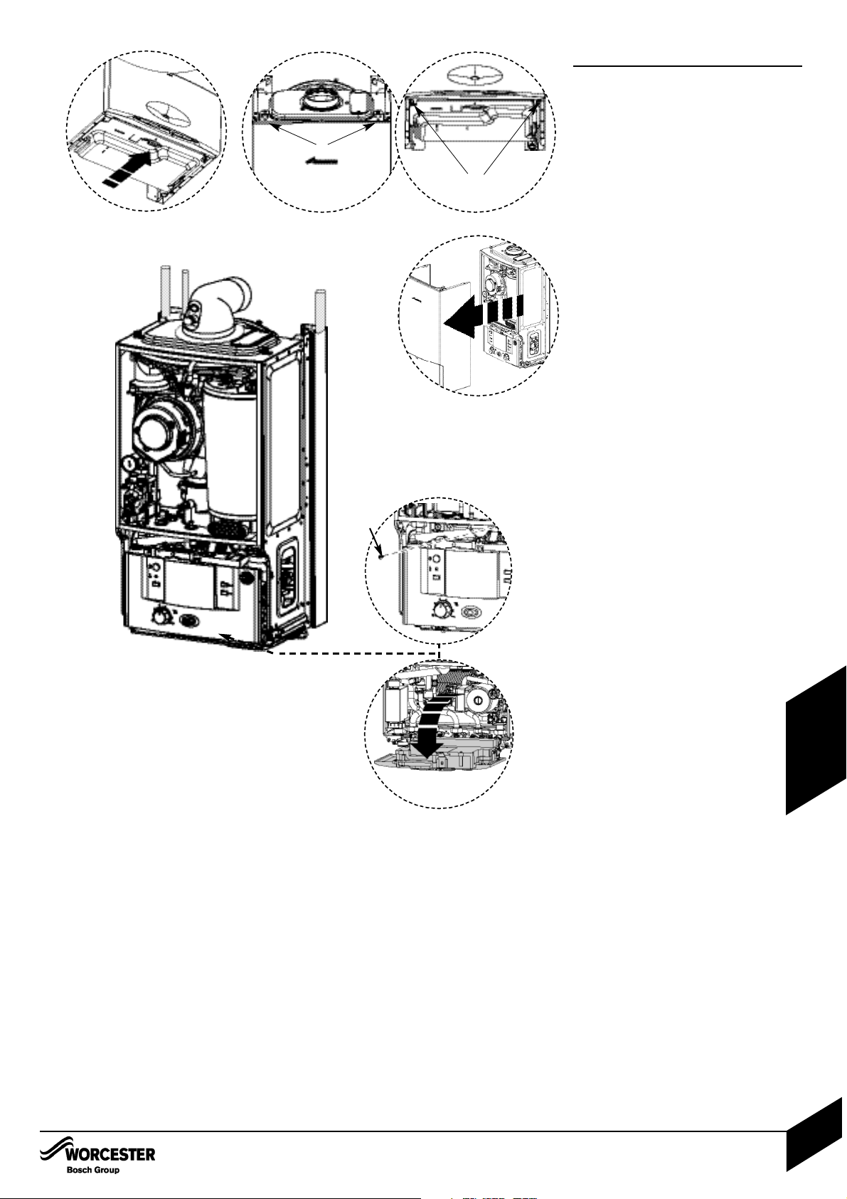
1. Removing outer case
1. Remove bottom panel by pulling it forward
and off.
1.1 Undo and remove 2 screws (A) securing
boiler casing at the top of the appliance.
1.2 Undo but do not remove the 2 screws
(B) securing boiler casing at the bottom of
the appliance.
1.3 Pull case forward and remove.
2. Adjusting boiler control to
service position
2.1 Remove screw (C) securing control.
2.2 Gently pull forward until it comes to
rest in service position.
Primary Heat Exchanger
There is a special accessory kit available
specifically designed for cleaning the
heat exchanger. If required order
7 716 192 312.
3 Check fan pressure at the test point next to
the fan using an electronic manometer.
The boiler must be run at maximum output.
Pressure will read negative and be greater
than:
Natural gas LPG
24i junior - 3.1 mbar 24i junior - 3.6 mbar
28i junior - 3.9 mbar 28i junior - 4.6 mbar
Pressures measured below these figures
will indicate that the heat exchanger will
require cleaning.
3
A
1.1 1.2
1.3
B
1.
C
2.1
2.2
INSPECTION AND SERVICE
INSTALLATION & SERVICI NG INSTRUCTIONS FOR WORC ESTER GR EENSTAR 24 i junior/28 i junior
8 716 107 336b (11/05)
36
SERVICING
& SPARES
Page 38
INSPECTION AND SERVICE
Setting Boiler to Maximum.
NOTE: When running in the service mode, the
boiler will operate both the Central Heating and
DHW circuits. This is to allow sufficient time for
the setting procedure.
It will be necessary to run water through the
DHW circuit to ensure that the boiler will not
cycle on low heating demands.
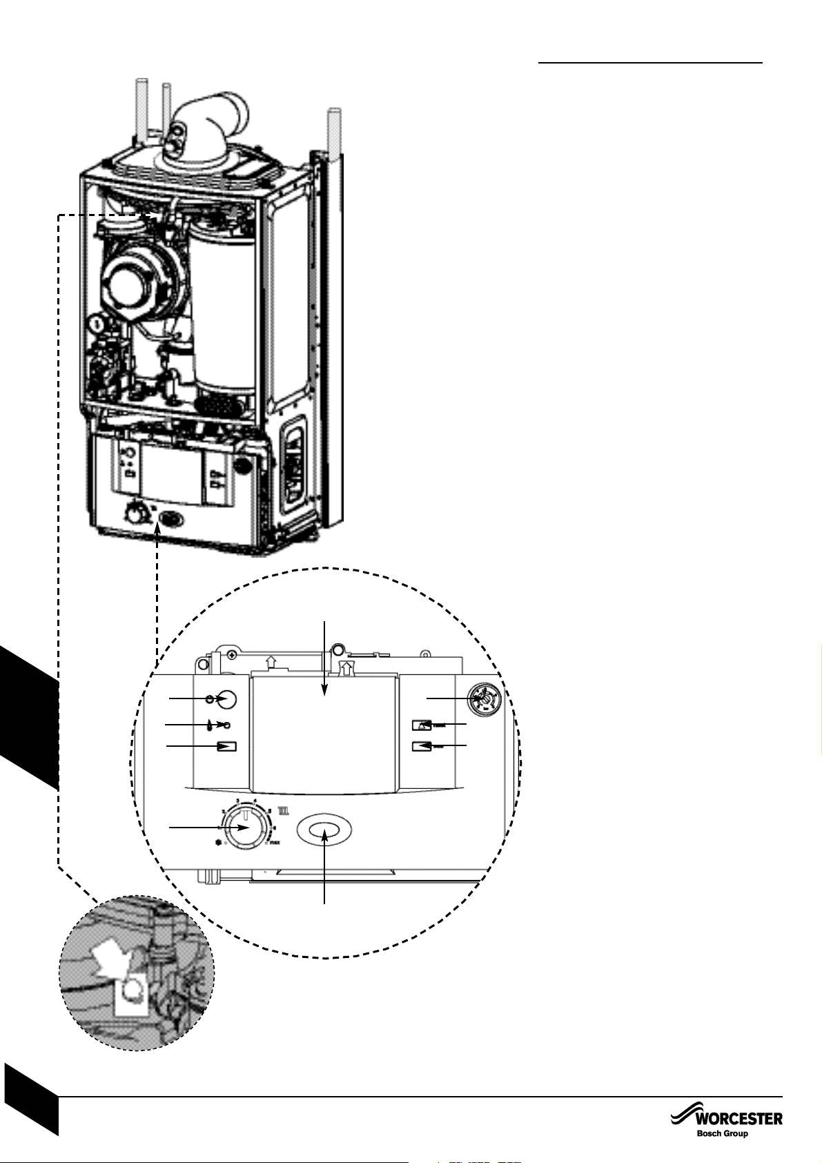
A - On/off button
B - On/off and fault indicator (BLUE)
C - Central heating temperature control
D - Burner indicator (GREEN)
E - Reset button
F - Service button
G - ECO button
H - System pressure gauge
I - Cover or optional programmer
1 Press and HOLD service button (F) for 10
seconds and set Central Heating temperature
to maximum.
• The service button will illuminate continually
and the blue power indicator will flash quickly.
• The boiler will stay in this mode for 15
minutes unless the service button is pressed
again.
2 Pull the cover off and connect a manometer
to the fan pressure test point.
After measurement replace test point cover.
Pressure will read negative and be greater than:
Natural gas LPG
24i junior - 3.1 mbar 24i junior - 3.6 mbar
28i junior - 3.9 mbar 28i junior - 4.6mbar
• Pressures measured below these figures
will indicate that the heat exchanger will
require cleaning.
There is a special accessory kit available
specifically designed for cleaning the
heat exchanger. If required order
7 716 192 312.
1
A
D
F
C
B
G
E
H
I
2
INSPECTION AND SERVICE
INSTALLATION & SERVICI NG INSTRUCTIONS FOR WORC ESTER GR EENSTAR 24 i junior/28 i junior
8 716 107 336b (11/05)
37
SERVICING
& SPARES
Page 39
INSPECTION AND SERVICE
To Clean the Heat Exchanger
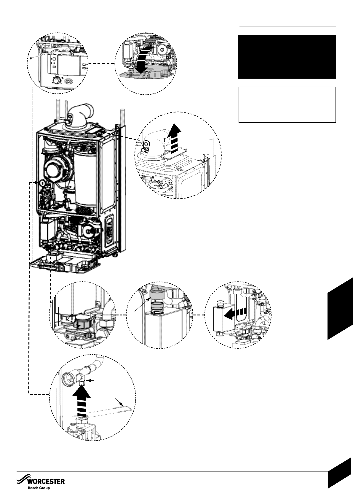
1 With outer case and base panel removed and
the power isolated from the appliance,
remove the cover panel (A) by removing the
retaining screw (B).
2 Remove clip (C) from gas valve outlet.
Pull gas adjustment assembly (D) free from
the plastic connection on the gas valve.
Pull gas adjustment assembly (D) forward to
clear case.
Removing Siphon
3.1 Undo plastic nut (E) on the siphon outlet.
Drop condensate tube away from siphon.
3.2 Remove hose (F).
3.3 Remove siphon
Siphon
The siphon body is transparent so contents
can be examined for any blockage.
If necessary flush with clean water.
1
A
B
2
C
D
3.3
3.2
3.1
F
E
INSPECTION AND SERVICE
INSTALLATION & SERVICI NG INSTRUCTIONS FOR WORC ESTER GR EENSTAR 24 i junior/28 i junior
8 716 107 336b (11/05)
38
SERVICING
& SPARES
COMBUSTION TESTING MUST BE CARRIED
OUT BY A COMPETE NT PERSON. IT MUST
NOT BE ATTEMPTED UNLESS THE PERSON
CARRYING OUT THE COMBUSTION CH ECK
IS EQUIPPE D WITH A COMBUSTION
ANALYSER CONFORM ING TO BS 7927 AND
IS COMPETENT IN IT’S USE.
IMPORTANT: IF THE JOINT
BETWEEN THE AIR/GAS MANIFOLD
AND THE HEAT EXCHANGER IS
DISTURBED THE SEALING GASKET
MUST BE REPLACED.
Page 40
INSPECTION AND SERVICE
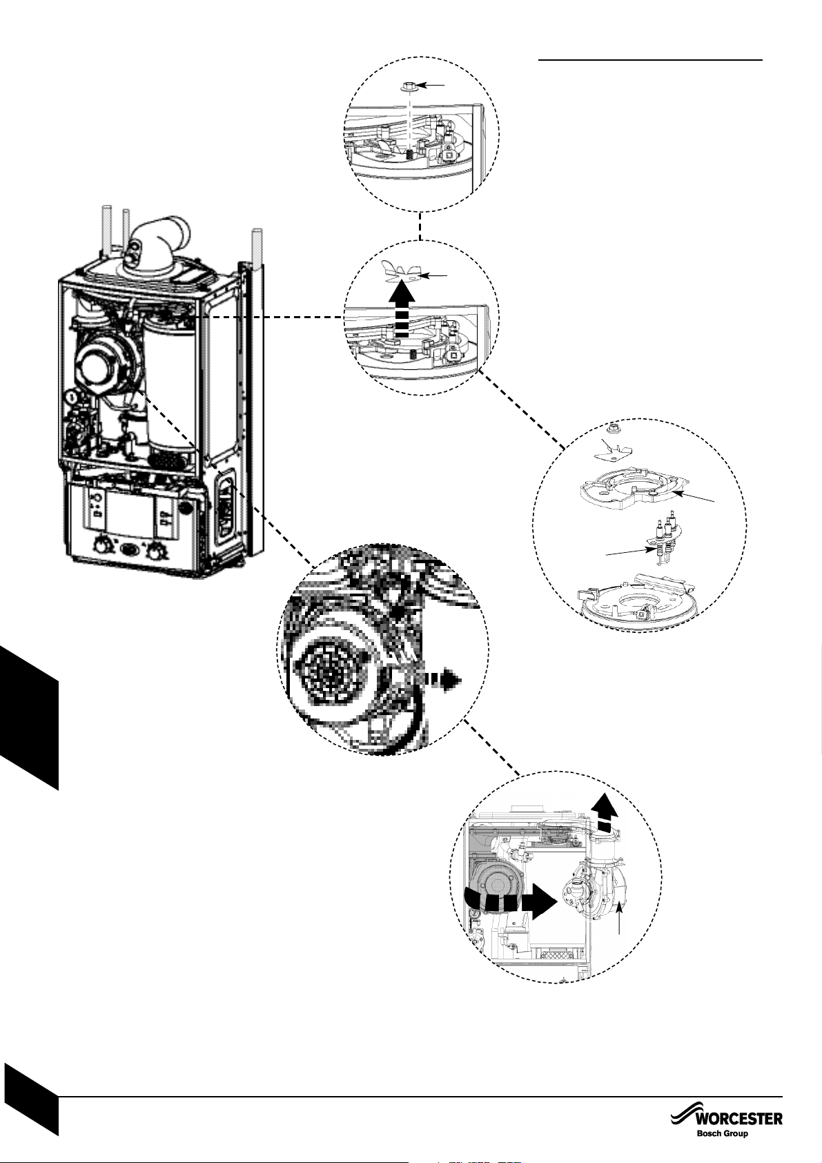
4 Remove electrical connector from fan.
5 Undo and remove securing nut (E) from the
top of the heat exchanger.
6 Remove stainless steel viewing mirror (F).
7 Rotate fan and air/gas manifold assembly (G)
around the top of the heat exchanger until it
stops at the lug.
Lift up assembly and remove from boiler.
8 Disconnect spark electrode and flame sensor
connections (J).
Remove clamping plate (K).
Remove spark/flame electrode assembly
from boiler.
Remove seal from the top of the heat
exchanger
5
6
E
F
8
K
J
7
G
4
INSPECTION AND SERVICE
INSTALLATION & SERVICI NG INSTRUCTIONS FOR WORC ESTER GR EENSTAR 24 i junior/28 i junior
8 716 107 336b (11/05)
39
SERVICING
& SPARES
Page 41
Q
INSPECTION AND SERVICE
INSTALLATION & SERVICI NG INSTRUCTIONS FOR WORC ESTER GR EENSTAR 24 i junior/28 i junior
8 716 107 336b (11/05)
40
SERVICING
& SPARES
INSPECTION AND SERVICE
9
L
M
N
0
P
R
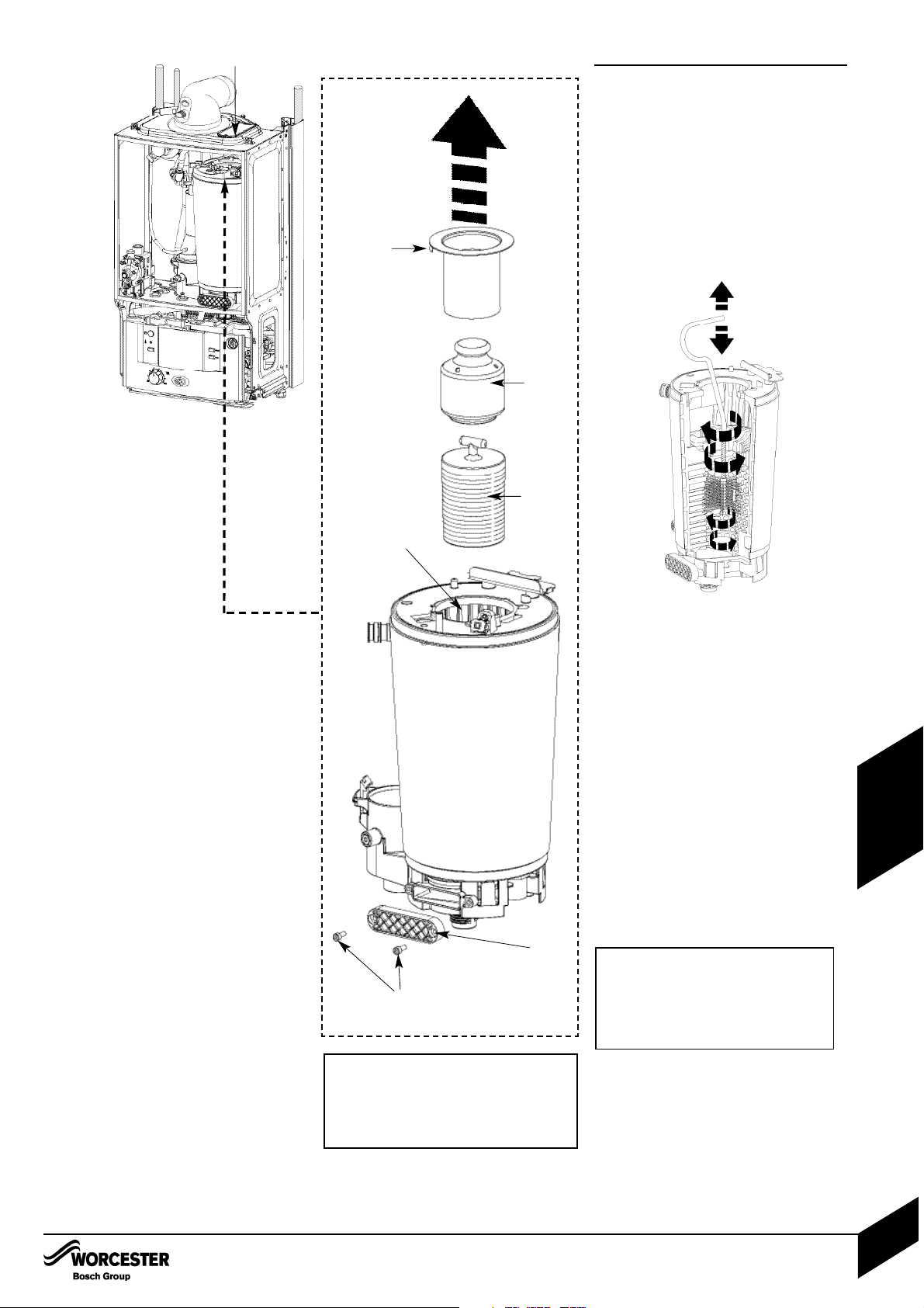
9 Remove burner (L).
Remove top baffle (M).
Remove baffle (N).
Remove the two hexagon headed screws (O)
retaining the access cover (P) on the sump.
Access the heat exchanger flue ways by
inserting the cleaning brush (7 716 192 312)
through the top access hole in the casing (Q).
Clean heat exchanger flue ways (R) using the
cleaning brush (7 716 192 312) removing
any debris from the access point in the sump.
Clean around sealing surface on sump and
replace access cover (P). Using a suitable
container to collect water from syphon
connection at the base of the boiler flush
heat exchanger with water.
Re-assemble ensuring that the lower baffle
(N) and the top baffle (M) are refitted
correctly.
When re-fitting the burner ensure that it fits
centrally within the heat exchanger and
location tabs are situated in location holes.
Ensure seal is replaced with new seal
and is correctly fitted.
Check the syphon unit for blockage before
refitting to boiler.
Reassemble and check combustion as
stated in the gas conversion section.
NOTE: To show the heat exchanger more
clearly it has been shown external to the
appliance
THE BAFFLES (N) AND (M) MUST
BE REFITTED INTO THE HEAT
EXCHANGER AS SHOWN IN 9.
FAILURE TO DO SO MAY RESULT
IN DAMAGE TO THE BOILER
IMPORTANT: IF THE JOINT
BETWEEN THE AIR/GAS MANIFOLD
AND THE HEAT EXCHANGER IS
DISTURBED THE SEALING GASKET
MUST BE REPLACED.
Small
tab
Page 42
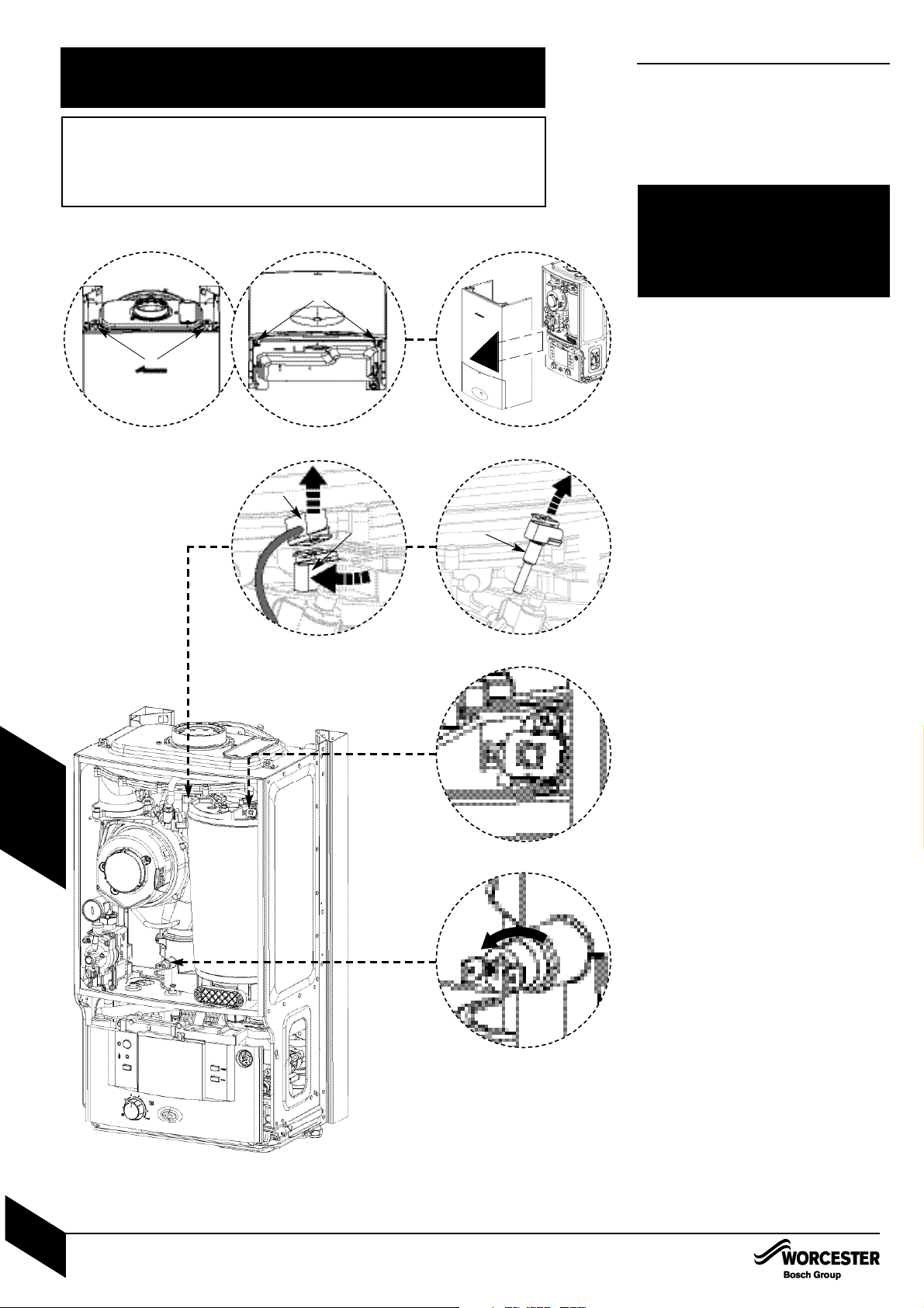
CAUTION: TURN OFF THE GAS SUPPLY AND ISOLATE THE MAINS
SUPPLIES BEFORE STARTING ANY WORK AND OBSERVE ALL
RELEVANT SAFETY PRECAUTIONS.
IMPORTANT: AFTER REPLACEMENT OF ANY COMPONENTS ALWAYS
CHECK FOR GAS SOUNDNESS WHERE RELEVANT AND CARRY OUT
FUNCTIONAL CHECKS AS DESCRIBED IN COMMISSIONING.
ANY O-RING OR GASKET THAT APPEARS DAMAGED MUST BE
REPLACED.
REPLACEMENT OF PARTS
1. Removing outer case
1.1 Undo 4 screws (A) securing boiler casing.
1.2 Pull case forward and remove.
To remove bottom tray, pull forward on the
tag on the underside of the tray.
2. Primary sensor
Remove electrical connection (B) by pulling
upwards. Squeeze retaining clip on plastic
moulding (C) and pull sensor (D) upwards
until clear of pocket in heat exchanger.
Coat new sensor with heat conductive
paste and replace.
3. Overheat thermostat
Remove two electrical connectors from
thermostat.
Slacken and remove fixing screw and
thermostat.
When replacing ensure thermostat sits
correctly on surface of the casting with the
left hand side of thermostat siting up
against the shoulder.
NOTE: It is essential that the mating surface of
the thermostat is coated with heat conductive paste.
4. Flue overheat thermostat
Remove electrical connections.
Unscrew thermostat from flue.
The following components can be
replaced with the outer case
removed:
Primary sensor
Overheat thermostat
Flue limit thermostat
A
1.1
2
1.2
A
3
4
B
D
C
REPLACEMENT OF PARTS
INSTALLATION & SERVICI NG INSTRUCTIONS FOR WORC ESTER GR EENSTAR 24 i junior/28 i junior
8 716 107 336b (11/05)
41
SERVICING
& SPARES
Page 43
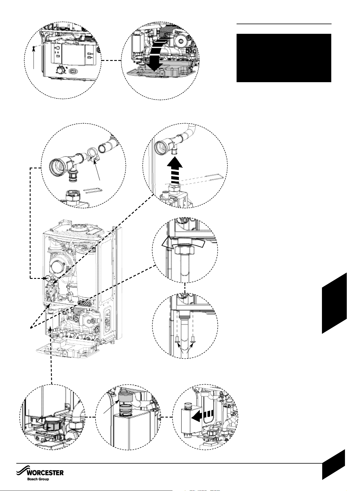
REPLACEMENT OF PARTS
5. Moving boiler control to service
position
5.1 Remove screw (A) securing control.
5.2 Gently pull forward.
6. Gas valve
Isolate gas supply at boiler gas cock.
6.1 Remove wire clip from gas valve outlet then
pull gas adjustment assembly free from
plastic connector and pull forward clear of
case.
6.2 Undo bottom gas connection to gas valve.
6.3 Undo two securing screws (C) on the
underside of casing.
Pull valve up and forward out of boiler.
Disconnect electrical connections.
Replace valve with new seals and check for
gas soundness.
Note: The valve will require setting; follow
procedure “Setting the gas/air ratio” in the gas
conversion section.
7. Gas adjuster
Isolate gas supply at boiler gas cock.
Repeat step 6.1 above.
Twist retaining clip (D) to release then
remove clip and tube.
Refit new adjuster and secure with clip.
8. Siphon
8.1 Undo plastic nut (E) on the siphon outlet.
Drop condensate tube away from siphon.
8.2 Remove hose (F).
8.3 Remove siphon.
The following components require
the control to be moved in to the
service position:
Gas valve
Siphon
PCB fuse
Transformer
5.1 5.2
A
6.2
6.3
6.1
7
8.3
8.2
8.1
D
F
C
E
REPLACEMENT OF PARTS
INSTALLATION & SERVICI NG INSTRUCTIONS FOR WORC ESTER GR EENSTAR 24 i junior/28 i junior
8 716 107 336b (11/05)
42
SERVICING
& SPARES
Page 44
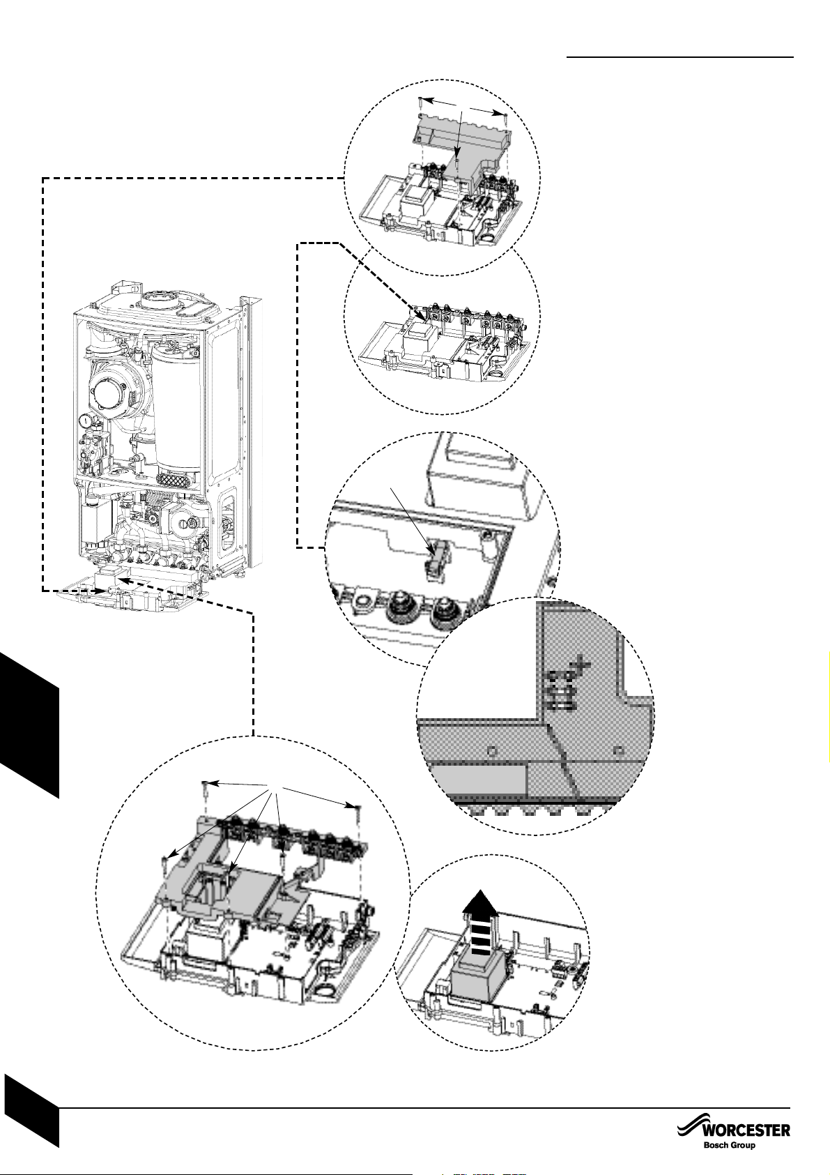
REPLACEMENT OF PARTS
9. Access to boiler control components
Remove 3 screws (A) and remove cover
from control.
10. PCB fuse
Remove fuse F1(B) from the PCB and
replace.
There is a spare fuse clipped into the
underside of the electrical cover.
11.Transformer / PCB
Disconnect all electrical connections from
the control.
Remove 5 screws (C) retaining the rear
panel of the control and remove panel.
9
11
A
C
C
REPLACEMENT OF PARTS
INSTALLATION & SERVICI NG INSTRUCTIONS FOR WORC ESTER GR EENSTAR 24 i junior/28 i junior
8 716 107 336b (11/05)
43
SERVICING
& SPARES
10
B
Spare Fuse order
T1.6L 250V F2
T2.5H 250V F1
T500L 250V F3
Page 45
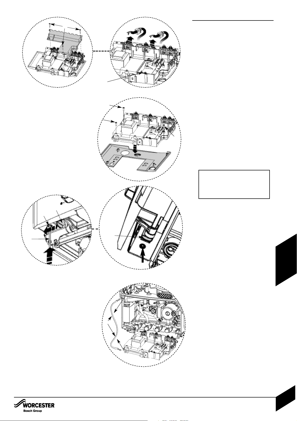
12.3
REPLACEMENT OF PARTS
12. Replacing control
The control is supplied within its plastic
housing. The complete unit must be replaced.
Remove ALLelectrical connections from
the control PCB including where cables run
through restraints. These can be unclipped
from the plastic moulding noting their
position.
Remove the code plug (B). The code plug
should be left attached to the frame of the
boiler by its plastic safety thread.
12.1
Remove the 3 screws (C) retaining the
front facia making sure to support the facia
when removing the last screw.
12.2
Using a suitable tool (D), press the button
(E) upwards and slide the control support
bracket (F) to the left.
12.3
Support the control and unclip control
support cable (G) from the boiler frame.
Remove the support cable and fit to the
new control.
Remove appropriate cable restraints from
the new control box.
Fit control to the boiler.
Re-connect support cable to the boiler and
all electrical connections to the new control.
IMPORTANT: ENSURE CODE PLUG
IS RE-FITTED TO THE NEW
CONTROL. IF THIS IS NOT DONE
THE BOILER WLL INDICATE
ERROR AND WILL NOT FUNCTION.
REPLACEMENT OF PARTS
INSTALLATION & SERVICI NG INSTRUCTIONS FOR WORC ESTER GR EENSTAR 12i System/24i System
8 716 107 375b (07/05)
44
SERVICING
& SPARES
12
A
12.1
C
C
C
12.2
F
E
F
D
E
G
B
Page 46
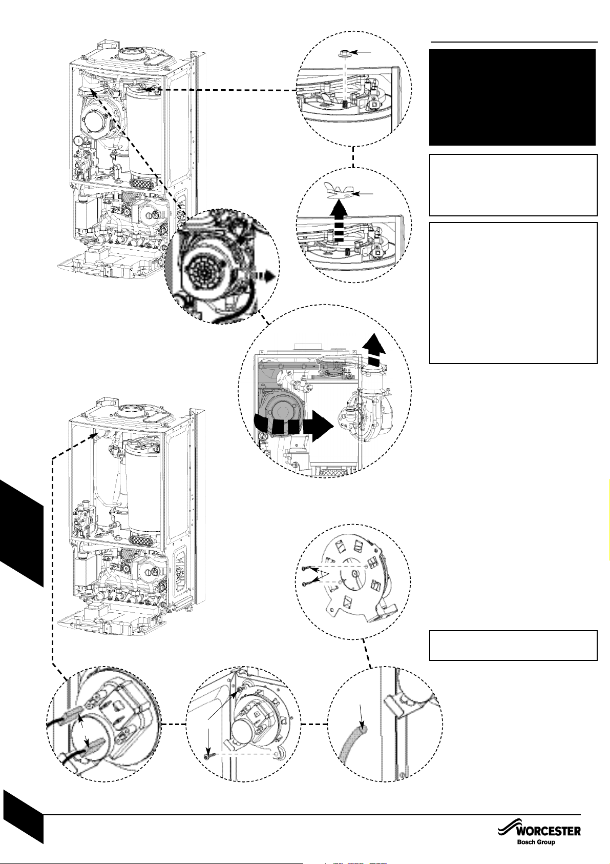
REPLACEMENT OF PARTS
13. Air / gas manifold and fan
assembly
Remove electrical connector from fan.
Remove wire clip from gas valve outlet then
pull gas adjustment assembly free from
plastic connector and pull clear of case
(see 6.1).
13.1
Undo and remove securing nut (A) from the
top of the heat exchanger.
13.2
Remove stainless steel viewing mirror (B).
13.3
Rotate fan and air/gas manifold assembly
(shaded) around the top of the heat
exchanger until the lug on the air/gas
manifold is visible.
Lift up assembly and remove from boiler.
14. Pressure switch
14.1
Remove electrical connections (C).
14.2
Slacken top retaining screw and remove
bottom screw. (D).
14.3
Remove tube (E).
14.4
Remove 2 screws (F) retaining pressure
switch to bracket.
Refit new pressure switch to bracket.
The following components require
the air / gas manifold and fan
assembly to be removed:
Pressure switch
Fan
Electrode assembly
Burner
Heat exchanger
13.1
13.2
14.4
14.314.214.1
A
B
C
D
E
F
13.3
IMPORTANT: IF THE JOINT
BETWEEN THE AIR/GAS MANIFOLD
AND THE HEAT EXCHANGER IS
DISTURBED THE SEALING GASKET
MUST BE REPLACED.
IMPORTANT: ENSURE TUBE IS
REFITTED TO PRESSURE SWITCH
IMPORTANT: AFTER REASSEMBLY
THE COMBUSTION MUST BE
CHECKED USING THE PROCEDURE IN THE SECTION “SETTING
THE GAS AIR RATIO”. MEASUREMENT AND SETTING (IF NECESSARY) OF THE GAS RATIO MUST
NOT BE ATTEMPTED UNLESS THE
PERSON IS EQUIPPED WITH A
COMBUSTION ANALYSER CONFORMING TO BS 7927 AND IS COMPETENT IN ITS USE.
REPLACEMENT OF PARTS
INSTALLATION & SERVICI NG INSTRUCTIONS FOR WORC ESTER GR EENSTAR 24 i junior/28 i junior
8 716 107 336b (11/05)
45
SERVICING
& SPARES
Page 47
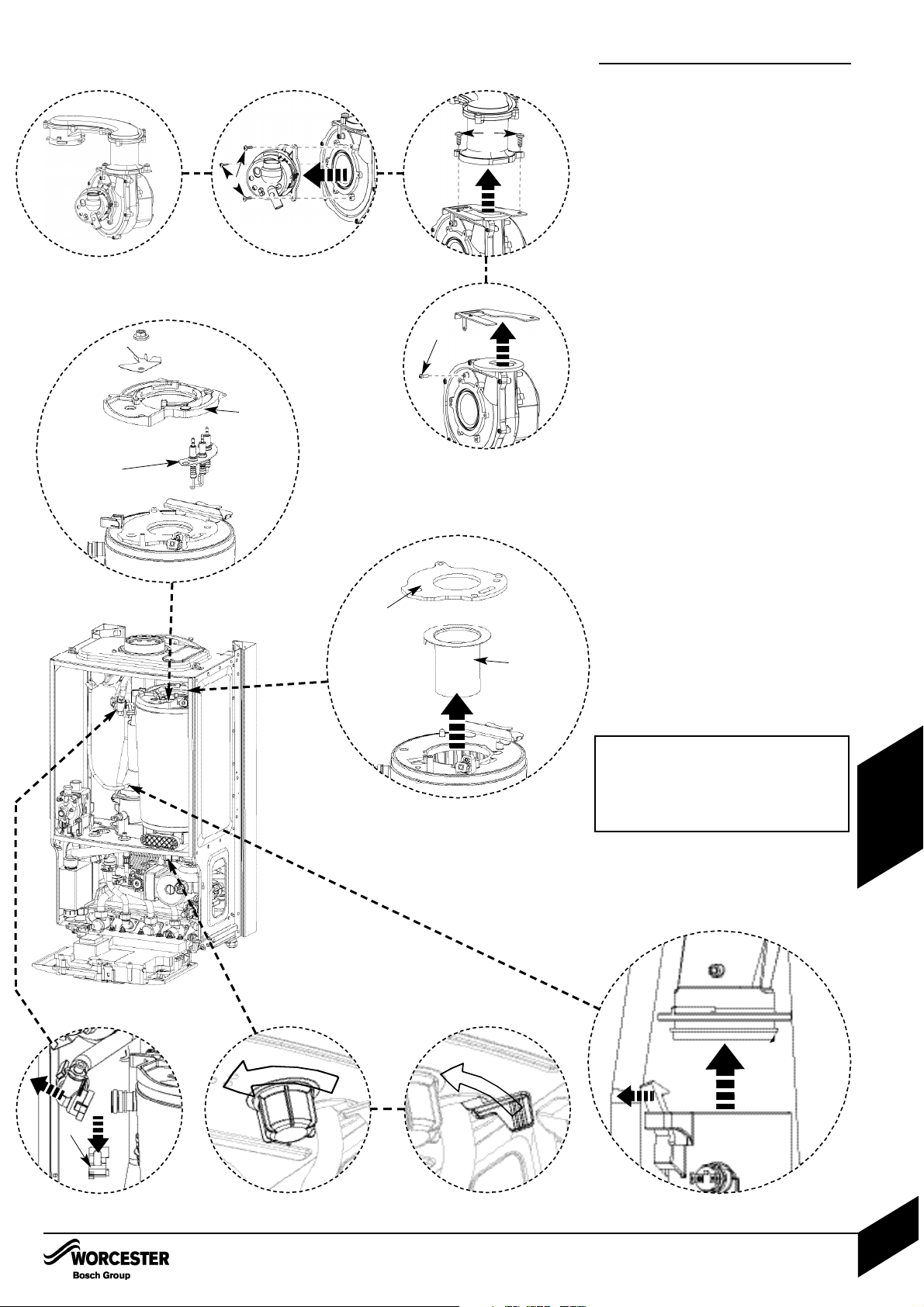
REPLACEMENT OF PARTS
15. Fan
15.1
Remove 3 screws (A) retaining mixing
chamber.
15.2
Remove 2 screws (B) retaining the fan to
the air/gas manifold.
15.3
Remove screw (C) retaining plate and
remove.
Re-assemble with new fan ensuring seals
are correctly fitted.
16. Electrode assembly
Disconnect spark electrodes and flame
sensor connection.
Remove clamping plate (D).
Remove spark/flame electrode assembly (E)
from heat exchanger.
17. Burner
Remove seal (F) from the top of the heat
exchanger.
Remove burner (G).
Replace new burner in correct position.
Ensure that burner tab fits correctly into hole.
Ensure that the seal is replaced with a new one.
18. Heat Exchanger
Isolate flow and return valves then drain the
boiler.
Remove siphon.
18.1
Remove clip from plastic elbow on the flow
pipe and pull flow pipe away from heat
exchanger.
18.2
Remove plastic nut from the bottom of
the boiler.
18.3
Rotate lever to release return pipe.
18.4
Undo flue connection from sump.
Pull heat exchanger assembly up to clear.
Reassemble and check combustion as
stated in the gas conversion section.
18.4
15.1 15.2
15.3
18.2
18.1
18.3
A
B
C
H
IMPORTANT: IF THE JOINT
BETWEEN THE AIR/GAS MANIFOLD
AND THE HEAT EXCHANGER IS
DISTURBED THE SEALING GASKET
MUST BE REPLACED.
REPLACEMENT OF PARTS
INSTALLATION & SERVICI NG INSTRUCTIONS FOR WORC ESTER GR EENSTAR 24 i junior/28 i junior
8 716 107 336b (11/05)
46
SERVICING
& SPARES
17
16
F
G
D
E
Page 48
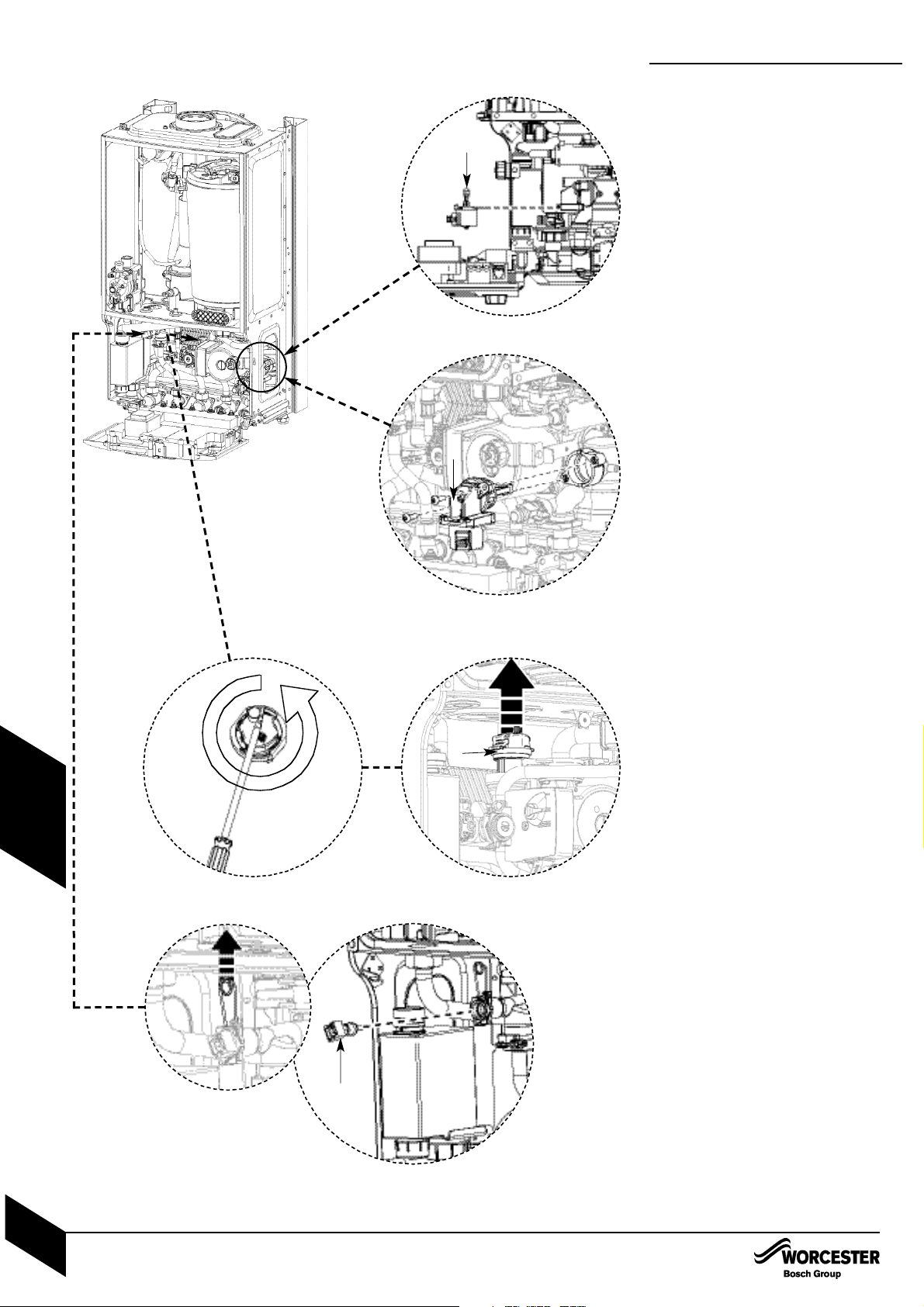
REPLACEMENT OF PARTS
19. Diverter valve motor
Insure the appliance is in service mode
(there is no need to drain the appliance).
Disconnect the electrical connector from the
diverter valve motor.
18.1
Pull the motor assembly (A) towards you. The
assembly will slide free from the valve.
To refit, follow the above in reverse.
20. Diverter valve
Ensure the appliance has been fully drained.
Disconnect the electrical connector from the
diverter valve motor.
Undo the two screws holding the valve to the
plastic housing.
20.1
Withdraw the valve (B) and clean the valve
chamber if necessary.
To refit, follow the above in reverse. Ensure
any seals that have been disturbed are
renewed.
21. Auto air vent
Ensure the appliance has been fully drained.
21.1
Use a screwdriver or similar to rotate the air
vent anticlockwise.
21.2
Lift the air vent (C) out of the housing and
remove.
To refit, follow the above in reverse.
22. DHW temperature sensor
Ensure the domestic hot water circuit is fully
drained (see draining the domestic hot water).
Disconnect the electrical connection from
the sensor.
22.1
Withdraw the spring clip.
22.2
Withdraw the sensor (D) from the housing.
To refit, follow the above in reverse.
19.1
A
21.2
C
20.1
B
22.2
D
22.1
REPLACEMENT OF PARTS
INSTALLATION & SERVICI NG INSTRUCTIONS FOR WORC ESTER GR EENSTAR 24 i junior/28 i junior
8 716 107 336b (11/05)
47
SERVICING
& SPARES
21.1
Page 49
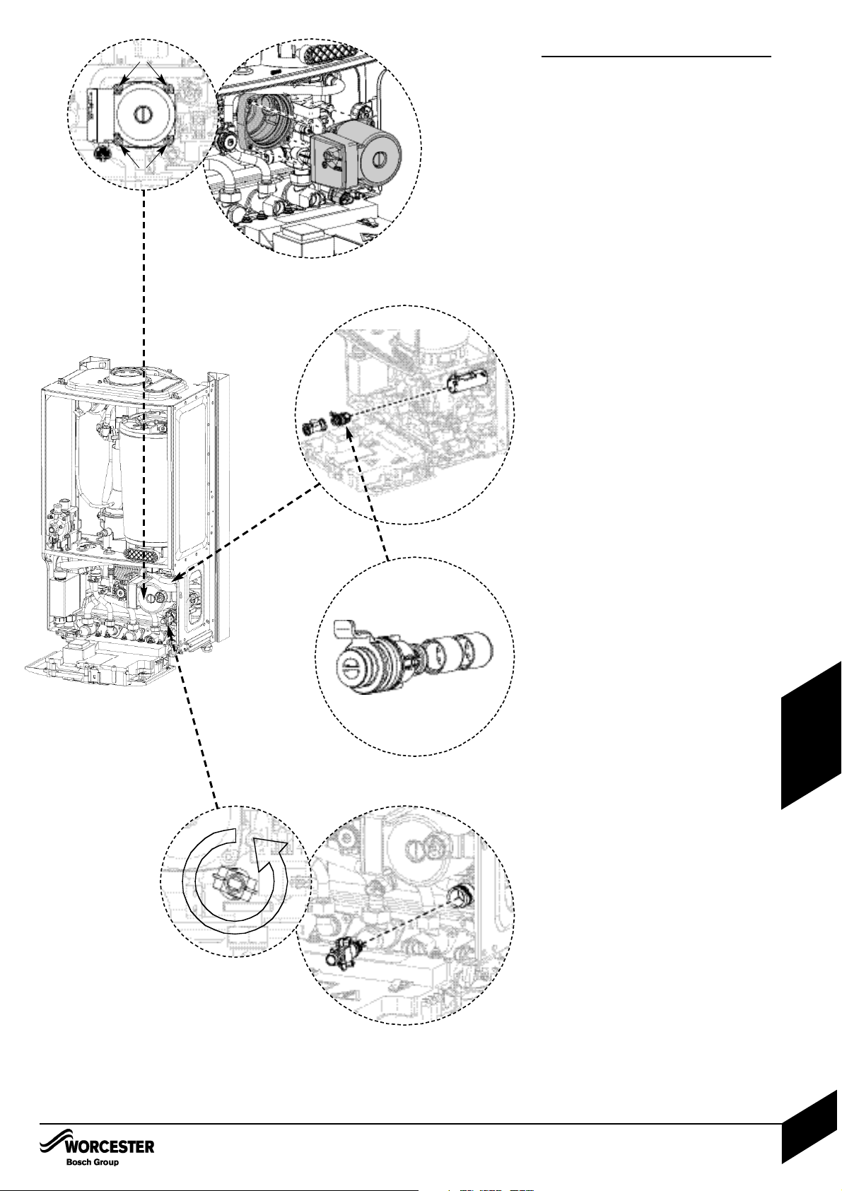
REPLACEMENT OF PARTS
23. Pump head
Ensure the boiler is fully drained (see
draining the appliance).
Disconnect the electrical connection from
the bottom of the pump.
23.1
Remove the four Allen bolts (A) securing the
pump at each corner.
23.2
Gently pull the pump towards you and
remove.
To refit, follow the above in reverse.
Pressure gauge
Ensure the appliance has been fully drained
(see draining the appliance).
Withdraw the spring clip from the pressure
sensing head housing.
Undo the nut on the rear of the pressure
gauge.
Remove the pressure sensing head and
pressure gauge capillary from the housing.
To refit, follow the above in reverse. DO NOT
omit the washer from the capillary when
fitting a replacement gauge.
24. Flow sensor, flow restrictor
housing and filter
Ensure the domestic hot water circuit is fully
drained (see draining the domestic hot water).
Disconnect the electrical connection to the
turbine.
Remove the spring clip from the housing and
move the brass pipe to one side.
24.1
Withdraw the flow sensor and filter from the
housing.
Using the cartridge tag, withdraw the flow
restrictor housing. If the regulator housing
has become stuck, a pair of long nosed pliers
may be used to grip the housing.
To refit, follow the above in reverse. Ensure
any seals that have been disturbed are
renewed.
25. Flow regulator
Remove the flow restrictor housing (See
Removing the flow sensor, flow restrictor
housing and filter).
25.1
Using a small Allen key or similar, push the
flow restrictor cartridge out of it’s housing.
To refit, follow the above in reverse. Ensure
any seals that have been disturbed are
renewed.
26. Drain tap
Ensure the appliance has been fully drained.
26.1
Rotate the drain tap fully anticlockwise.
26.2
Withdraw the drain tap from its housing
To refit, follow the above in reverse. Ensure
any seals that have been disturbed are
renewed.
23.2
24.1
23.1
26.2
26.1
25.1
A
A
REPLACEMENT OF PARTS
INSTALLATION & SERVICI NG INSTRUCTIONS FOR WORC ESTER GR EENSTAR 24 i junior/28 i junior
8 716 107 336b (11/05)
48
SERVICING
& SPARES
Page 50
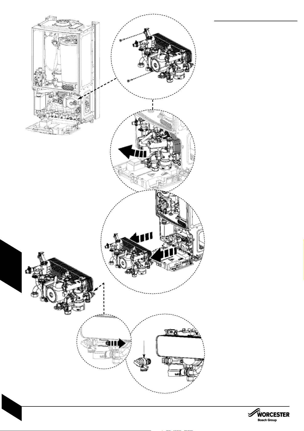
REPLACEMENT OF PARTS
27. Hydraulic Block
Ensure the appliance has been fully drained
(see draining the appliance).
Disconnect the electrical connections to the
NTC, Turbine and pump.
Undo the nuts securing the copper water
pipes to the manifold (there is no need to
remove the gas pipe)
Release the spring clips securing these
water pipes to the plastic housing and
remove the pipes.
Release the spring clip securing the
expansion vessel pipe to the plastic housing
and remove the pipe.
Undo the nut securing the pressure gauge to
its bracket and remove the gauge.
Release the locking devices that secure the
two copper water pipes leading to the
combustion chamber by squeezing the two
tabs together and rotating anticlockwise
(viewed from above).
Remove the rubber pipe connecting the
sump and remove the syphon. NOTE: this is
not essential but makes the removal of the
block easier.
27.1
Undo the two screws securing the hydraulic
block to the chassis (located top left / top
right of the housing)
27.2
Lift the left hand side of the block slightly,
then manoeuvre the block out, starting with
the right hand side.
Take care not to snag the harness or
pressure gauge bracket.
NOTE: the block will still contain a small amount
of water, which will spill if the block is tilted.
To refit, follow the above in reverse. Ensure
any seals that have been disturbed are
renewed.
28. CH pressure relief valve
Remove the hydraulic block from the boiler
(See Removing the Hydraulic Block).
28.1
Remove the spring clip from the Pressure
relief valve housing.
28.2
Withdraw the pressure release valve (A) from
its housing.
To refit, follow the above in reverse. Ensure
any seals that have been disturbed are
renewed.
27.2
27.1
28.2
A
28.1
REPLACEMENT OF PARTS
INSTALLATION & SERVICI NG INSTRUCTIONS FOR WORC ESTER GR EENSTAR 24 i junior/28 i junior
8 716 107 336b (11/05)
49
SERVICING
& SPARES
Page 51
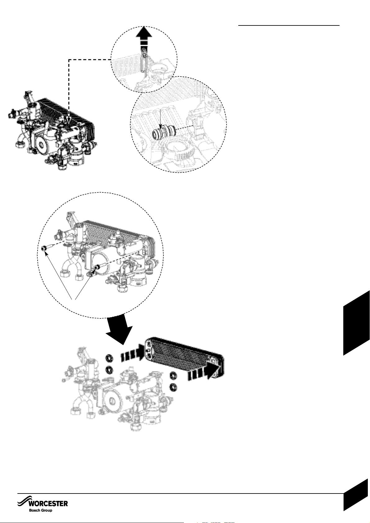
REPLACEMENT OF PARTS
29. Plastic protection device
Ensure the system is fully drained (see
draining the appliance).
Disconnect all pipes connected to the pump
housing.
Remove the electrical connection to the
pump.
Withdraw the metal clip to the right of the
pump head to release the pump housing.
Slide the device to the left and then withdraw
it from the appliance.
29.1
Remove the spring clip from the pressure
relief valve housing.
29.2
Withdraw the pressure relief valve (A).
To refit, follow the above in reverse. Ensure
any seals that have been disturbed are
renewed.
30. DHW Heat exchanger
Remove the Hydraulic block from the boiler
(See Removing the Hydraulic Block).
30.1
Undo the two screws (B) securing the plastic
housings to the heat exchanger.
30.2
Remove the heat exchanger
To refit, follow the above in reverse. Ensure
any seals that have been disturbed are
renewed.
29.2
A
29.1
30.1
30.2
B
REPLACEMENT OF PARTS
INSTALLATION & SERVICI NG INSTRUCTIONS FOR WORC ESTER GR EENSTAR 24 i junior/28 i junior
8 716 107 336b (11/05)
50
SERVICING
& SPARES
Page 52
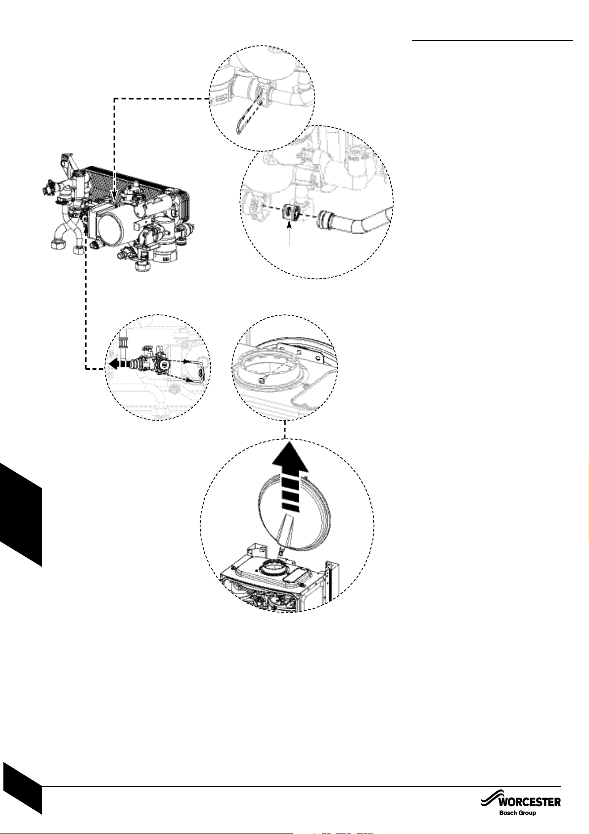
REPLACEMENT OF PARTS
31. Bypass valve
Remove the Hydraulic block from the boiler
(See Removing the Hydraulic Block).
31.1
Remove the two spring clips at either end of
the copper bypass pipe.
Undo the screw securing the left hand
plastic housing to the heat exchanger
Move the housing to the left to free up the
one end of the pipe.
Remove the pipe from the right hand housing
to reveal the bypass valve
31.2
Using a pair of pliers, pull out the bypass
valve (A) from the housing
To refit, follow the above in reverse. Ensure
any seals that have been disturbed are
renewed.
32. Expansion vessel
The expansion vessel can be replaced with the
boiler in position if there is a side exit flue fitted
and there is a minimum clearance of 340mm
above the boiler casing. If vertical flue is fitted
then a similar clearance to one side and the flue
is required.
If clearance is not available, the boiler will need to
be removed from the mounting frame to gain
access to the expansion vessel.
Alternatively a second vessel of at least the
capacity of 7lts can be fitted to the return from
the heating system as close as possible to the
boiler.
Expansion vessel replacement
(Boiler in place)
Isolate mains power from the boiler.
Place the controls in service position.
Isolate the boiler from the heating system
(and cylinder return if internal diverter valve is
fitted) using service valves.
Drain boiler.
32.1
Remove clip from expansion vessel
connection.
32.2
Remove screw retaining the vessel to the top
of the boiler casing.
32.3
Pull the vessel up and out over the flue
system or to one side if fitted with a vertical
flue.
Remove the flexible hose from the expansion
vessel and fit to the replacement vessel
using a new seal. Ensure that the connection
to the boiler will be pointing to the right hand
side of the appliance when fitted.
Reassemble expansion vessel into boiler and
connect flexible pipe to boiler.
Removing boiler
Isolate electrical supply.
Isolate system and gas connections at the
service valves.
Drain boiler.
Disconnect electrical supply and any external
controls.
Disconnect flue connection from the boiler.
Undo connection to boiler at the service valves.
Remove clip from expansion vessel
connection to the boiler.
Gently raise the boiler off the mounting frame.
Replace expansion vessel and refit the boiler
to the mounting frame.
Follow the commissioning procedure in this
manual.
31.2
A
31.1
32.3
32.1
32.2
REPLACEMENT OF PARTS
INSTALLATION & SERVICI NG INSTRUCTIONS FOR WORC ESTER GR EENSTAR 24 i junior/28 i junior
8 716 107 336b (11/05)
51
SERVICING
& SPARES
Page 53
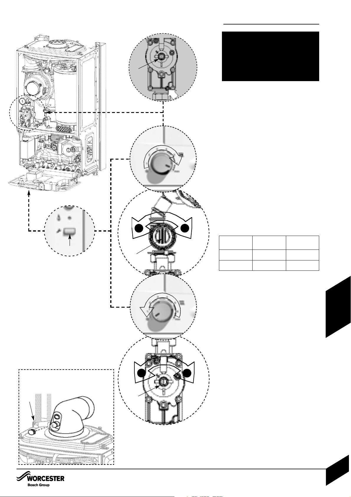
33. Setting the CO
2
Note: When running in the service mode, the
boiler will operate both the central heating &
DHW circuits. This is to allow sufficient time for
the setting procedure. It will be necessary to run
water through the DHW circuit to ensure that
the boiler will not cycle on low heating demands.
5.1 Connect manometer to inlet pressure point
on the gas valve.
To adjust the CO
2
it will be necessary to first
operate the boiler at maximum output.
Press and hold down the service button (A) for
10 seconds until illuminated. The blue power
indicator will flash.
5.2 Turn central heating control to maximum; the
boiler will then go to maximum output.
Note: The control will resume normal operation
after 15 minutes or if the service button is pressed
for over a second.
5.3 Using a flat blade screwdriver set the CO
2
via adjuster (B) using table below.
Check CO is less than 200ppm.
Measure the inlet pressure; it should be no
less than 18.5mb for natural gas and 37mb
for LPG.
5.4 Set the central heating control to minimum.
This will make the boiler go to minimum power.
5.5 Measure the CO
2
; it should now be at the
figure for minimum output. If not adjust (C)
on the gas valve until correct.
Return to maximum and re-check the CO
2
. If
correct press and hold down the service
button for 2 seconds; the button will cease to
be illuminated and the blue power indicator will
be permanently illuminated.
Remove manometer and re-seal inlet pressure
point on gas valve.
Fit new plastic sealing cover on to outlet
adjuster (B).
Fit white cover over valve adjuster (C) and
secure with black security tag.
Remove red arrow from data plate and fit new
one in correct position for gas type.
Re-assemble and refit boiler case.
Re-connect mains electrical supply and
check boiler operation as stated in the
commissioning section.
Fit new label from kit over existing label on the
appliance bottom panel.
33.1
33.3
5.5
33.4
Inlet Test Nipple
+
–
C
B
C
+
–
Gas type
CO2settings
Note. CO2 should be measured after 10 minutes
Natural gas
LPG
9.8% ±0.2
11.0% ±0.2
9.2% ±0.2
10.5% ±0.2
CO2setting
maximum
CO2setting
minimum
33.2
SETTING THE GAS / AIR RATIO
A
THE SETTING OF THE GAS RATIO MUST BE
CARRIED OUT BY A COMPETENT PERSON.
SETTING OF THE GAS RATIO MUST NOT BE
ATTEMPTED UNLESS TH E PER SON
CARRYING OUT THE CONVERSION IS
EQUI PPED WITH A COM BUSTION ANALYSER
CONFORMING TO BS 7927 AND IS
COMPETENT IN ITS USE.
REPLACEMENT OF PARTS
INSTALLATION & SERVICI NG INSTRUCTIONS FOR WORC ESTER GR EENSTAR 24 i junior/28 i junior
8 716 107 336b (11/05)
52
SERVICING
& SPARES
Please note: The flue gas test point can be
accessed on the appliance flue elbow by
removing cap D
D
Page 54
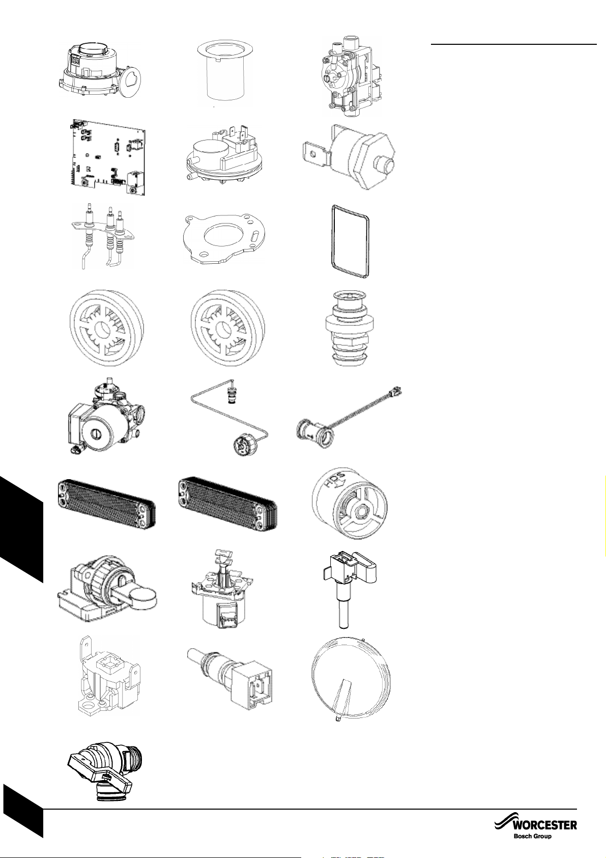
SHORT PARTS LIST
1 Fan
WORCESTER Part No. 8 717 204 453 0
GC No. H26 536
2 Burner
WORCESTER Part No. 8 718 120 609 0
GC No. H26 538
3 Gas valve
NG WORCESTER Part No. 8 716 107 052 0
NG GC No. H26 540
LPG WORCESTER Part No. 8 716 107 053 0
LPG GC No. H26 539
4 Control board
WORCESTER Part No. 8 716 109 539 0
GC No. H28 966
5 Air pressure switch
WORCESTER Part No. 8 716 106 633 0
GC No. H26 543
6 Temperature limit sensor
WORCESTER Part No. 8 722 963 858 0
GC No. H08 291
7 Electrodes
WORCESTER Part No. 8 718 107 087 0
GC No. H26 544
8 Gasket - burner/electrodes
WORCESTER Part No. 8 716 106 506 0
GC No. H26 545
9 Seal - inner case/mantel
WORCESTER Part No. 8 716 106 635 0
GC No. H26 546
10 Flow reg. Type E 8 litre
WORCESTER Part No. 8 716 141 143 0
GC No. 379 215
11 Flow reg. Type E 10 litre
WORCESTER Part No. 8 716 107 044 0
GC No. 394 291
12 Pressure relief valve DHW
WORCESTER Part No. 8 717 401 029 0
GC No. H02 526
13 Pump assembly 3 speed
WORCESTER Part No. 8 716 106 355 0
GC No. H02 527
14 Pressure gauge
WORCESTER Part No. 8 717 208 107 0
GC No. H02 528
15 Flow sensor
WORCESTER Part No. 8 716 107 223 0
GC No. H02 529
16 Heat exchanger 12 plate
WORCESTER Part No. 8 716 106 686 0
GC No. H02 538
17 Heat exchanger 16 plate
WORCESTER Part No. 8 716 106 685 0
GC No. H02 531
18 By-pass valve
WORCESTER Part No. 8 716 106 434 0
GC No. H02 532
19 Diverter valve assembly
WORCESTER Part No. 8 716 106 845 0
GC No. H02 533
20 Diverter valve motor
WORCESTER Part No. 8 716 106 847 0
GC No. H02 534
21 Control sensor - primary
WORCESTER Part No. 8 716 106 688 0
GC No. H26 542
22 High limit stat
WORCESTER Part No. 8 707 206 196 0
GC No. H26 584
23 DHW temperature sensor
WORCESTER Part No. 8 714 500 081 0
GC No. H02 538
24 Expansion vessel
WORCESTER Part No. 8 716 105 545 0
GC No. H05 206
25 Pressure relief valve
WORCESTER Part No. 8 716 106 431 0
GC No. H09 750
1 2 3
4 5 6
7 8 9
10 11 12
13 14 15
16 17
18
19 20
21
22
REPLACEMENT OF PARTS
INSTALLATION & SERVICI NG INSTRUCTIONS FOR WORC ESTER GR EENSTAR 24 i junior/28 i junior
8 716 107 336b (11/05)
53
SERVICING
& SPARES
24
23
25
Page 55
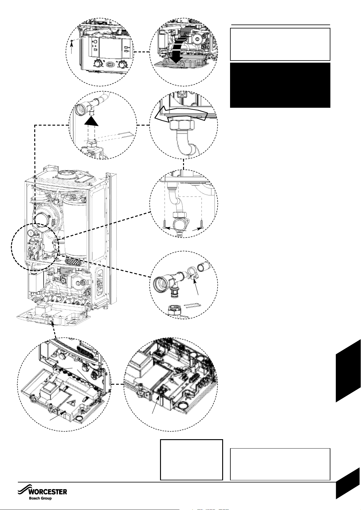
1.1 1.2
A
2.2
2.3
2.1
3
C
B
THE GAS / AIR RATIO MUST BE
RESET AFTER CONVERSION. THE
PROCEDURE CAN BE FOUND IN
THE REPLACEMENT PARTS SECTION
OF THIS MANUAL.
4.1 4.2
D
E
A
L. P. G. CONVERSION
L.P.G. CONVERSION
INSTALLATION & SERVICI NG INSTRUCTIONS FOR WORC ESTER GR EENSTAR 24 i junior/28 i junior
8 716 107 336b (11/05)
54
CONVERSION
KITS
Important: The appliance shall not be installed
into a room or internal space below ground
level when it is intended for use with LPG
(propane - G31). This does not preclude the
installation into a room or space which is a
basement on one side of the building but open
to ground on the opposite side.
Installation Regulations
In addition to those specified in the main
booklet the following standard applies when
converting to an LPG appliance: BS 5842
Domestic Propane Gas Burning
Installations.
All conversions will require the air gas ratio to
be set correctly for the gas used. The
procedure for setting the air gas ratio is at
the rear of these instructions.
1. Moving boiler control to service
position
Remove boiler case, as described on page
36.
1.1 Remove screw (A) from retaining bracket.
1.2 Lower control panel into service position.
2. Gas valve
Isolate gas supply at boiler gas cock.
2.1 Remove wire clip from gas valve outlet then
pull gas adjustment assembly free from
plastic connector and pull forward clear of
case.
2.2 Undo bottom gas connection to gas valve.
2.3 Undo two securing screws (B) on the
underside of casing.
Pull valve up and forward out of boiler.
Disconnect electrical connections.
Fit plastic retaining nut to the outlet of the
gas valve from the kit and hand tighten.
Replace valve with new seals.
Check for gas soundness.
3. Gas adjuster
Twist retaining clip (C) to release then
remove clip and tube.
Refit new adjuster and secure with clip.
Coloured red for LPG or black for NG.
4. Code plug
4.1 Remove 3 screws (D) retaining plastic
cover at rear of control box and remove.
4.2 Replace code plug (E) with new one
supplied with conversion kit.
Replace plastic cover.
Place control in normal position and secure
with screw.
ISOLATE MAINS ELECTRICAL
SUPPLY AND REMOVE OUTER CASE
AS SHOWN IN THE INSTALLATION,
COMMISSIONING & SERVICING
INSTRUCTIONS
THE CONVERSION MUST BE CARRIED OUT
BY A COMPETENT PERSON. IT MUST NOT
BE ATTEMPTED U NLESS THE PE RSON
CARRYING OUT THE CONVERSION IS
EQUI PPED WITH A COM BUSTION ANALYSER
CONFORMING TO BS 7927 AND IS
COMPETENT IN IT’S USE.
Code plugs
24kW NG - 100
24kW LPG - 101
28kW NG - 102
28kW LPG - 103
Page 56
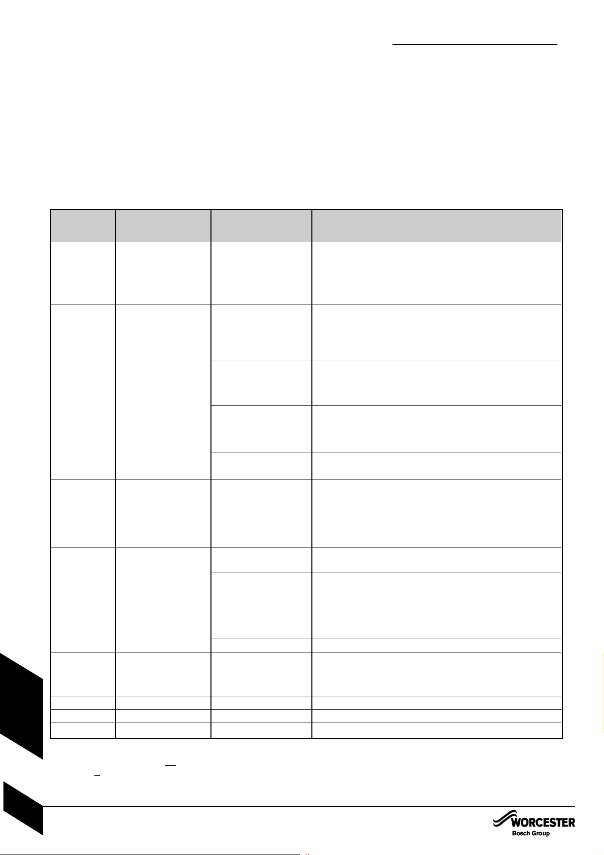
FAULT FINDING
INSTALLATION & SERVICI NG INSTRUCTIONS FOR WORC ESTER GR EENSTAR 24 i junior/28 i junior
8 716 107 336b (11/05)
55
FAU LT F I N DING
& DIAGRAMS
Off
On
Slow flash
(normally off,
flashes on)
Slow flash
(normally on,
flashes off)
Fast flash
Fast flash
2 pulses
5 pulses
Off
Off
Flashing (reset required)
Flashing (reset required)
Off
Flashing
No light
No light
Permanent mains supply to boiler.
Boiler mains switch.
Fuse F1, 2.5A or Fuse F3, 0.5A
Transformer (both coils below 100Ω).
Otherwise replace control board.
Live demand at ST10-L
R (from external roomstat/timer).
Facia mounted timer (if fitted).
CH knob in winter position.
Diverter valve.
Control board.
Some older thermostats (containing capacitors) may give a low
voltage return at ST10-LR when the thermostat contacts are open.
Check that there is not a permanent live at ST10-LR from another
source.
See Flow Sensor Test below.
or
Diverter valve.
Control board.
Fan.
Control board.
Gas present and at correct pressure.
Combustion CO2level.
Flue condition.
Ignition electrodes / harness / connections.
Gas valve (coils 140-190Ω) / low voltage harness connection.
Otherwise replace control board.
Heat exchanger blocked.
Heat exchanger baffles removed and not refitted.
Water pressure.
All air vented.
Pump / harness / connections.
Water leaks / blockages.
Safety thermostats / low voltage wiring harness / connections.
Otherwise replace control board.
Blockage in flue system.
Temperature sensor (8000-20,000Ω).
Low voltage wiring harness / connections to sensor.
Fan / fan harness / connections to fan.
Code plug fitted.
Replace control board
Service mode selected to min, press service button to return to normal.
Service mode selected to max, press service button to return to normal.
NOTE : This fault finding information is for guidance only. Worcester cannot be held responsible for costs incurred by persons not deemed
to be competent.
The electronic control system for this boiler incorporates a blue central indicator. This normally confirms the permanent mains supply but, by
flashing at different rates during a fault, provides a guide to the cause as listed.
This fault finding system assumes that the appliance has been operating normally until the time of failure (i.e. not a first installation error).
PRELIMINARY CHECKS : Preliminary electrical system checks are the first electrical checks to be carried out during a fault-finding
procedure. On completion of the Service/Fault-Finding task which has required the breaking and remaking of electrical connections, check
(a) EARTH CONTINUITY, (b) SHORT CIRCUIT CHECK, (c) POLARITY and (d) RESISTANCE TO EARTH.
FAULT FINDING
Blue light
indication
Lockout reset
button
Possible solution/check
Fault
No power at control board
Boiler not operating during
central heating demand
(HW ok)
Boiler operating
without live demand at
ST10-LR (from external
roomstat timer).
Boiler not operating during
hot water demand (CH ok).
Boiler not operating during
any demand.
Ignition lockout
Flue overheat
Heat exchanger overheat
Flue blockage
Volatile lockout
Internal fault
Not a fault code
Not a fault code
Flow Sensor Test
:Replace control board if: 5V is not across the red and black cables.
:1.5V-3.5V is across the yellow and black cables (with water flowing).
Otherwise replace flow sensor.
Page 57
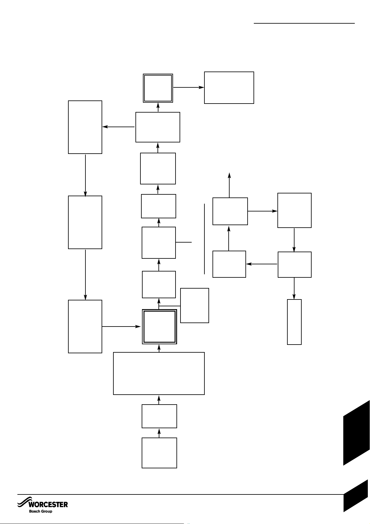
CENTRAL HEATING FUNCTION
NO
YES
POWER
SWITCH
ON
CENTRAL
HEATING
DEMAND
Fan to
start
speed.
Diverter valve
in CH position
Pump ON.
IGNITION
SEQUENCE
(see detail)
BLUE
LIGHT
ON
BURNER
LIT?
GREEN
FLAME
LIGHT
ON
Stop spark.
Wait
10 seconds
5th
attempt?
LOCKOUT
10 second
stabilisation
period.
Fan (& gas)
modulation
to achieve
set
temperature
(40-82°C)
END OF
BOILER
DEMAND
Gas valve
OFF
Pump run 3
minutes
Fan run 30
seconds
Over temperature shut-
down if water tempera-
ture is 5°C above set
value.
Gas valve OFF.
Fan overrun
30 seconds
3 minute wait
Spark
ignition
4 seconds
NO
YES
Room
thermostat and/or
mains
programmer ON
(or link fitted at
ST10)
AND
Facia mounted
programmer (if fit-
ted) ON
AND
CH control knob
ON
IGNITION SEQUENCE
CENTRAL HEATING FUNCTION
INSTALLATION & SERVICI NG INSTRUCTIONS FOR WORC ESTER GR EENSTAR 24 i junior/28 i junior
8 716 107 336b (11/05)
56
FAULT FINDING
& DIAGRAMS
Page 58
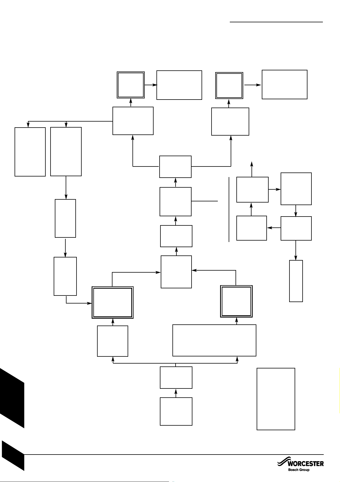
Wait
5 seconds
IGNITION
SEQUENCE
(see detail)
PREHEAT AND DHW FUNCTION
NO
YES
POWER
SWITCH
ON
Tap open
(recognised
by flow
turbine)
Diverter valve
in DHW
position
Pump ON.
BLUE
LIGHT
ON
BURNER
LIT?
Fan to
start
speed.
Stop spark.
Wait
10 seconds
5th
attempt?
LOCKOUT
Fan (& gas)
modulation
to achieve
set
temperature
(40-60°C)
DEMAND
END
Gas valve
OFF
Pump run 3
minutes
Fan run 30
seconds
Over temperature shut-
down if water tempera-
ture is 8°C above set
value.
Gas valve OFF.
Spark
ignition
4 seconds
NO
YES
ECO button
not
illuminated *
(ie preheat
requested)
AND
20 minutes
since last pre-
heat demand
AND
temperature
at least 10°
below set
point.
PREHEAT
DEMAND
DOMESTIC
HOT
WATER
DEMAND
(priority over
all other
demands)
GREEN
FLAME
LIGHT
ON
Burner shut down if
primary temperature
94°C
(until 84°C)
Fan (& gas)
modulation
to achieve
(55°C)
DEMAND
END
Gas valve
OFF
Stop pump
Stop fan
IGNITION SEQUENCE
*Set by
pressing ECO button. If pro-
grammer is fitted this is set by
a combination of programmer
(DHW) demand and ECO
button.
PREHEAT AND DHW FUNCTION
INSTALLATION & SERVICI NG INSTRUCTIONS FOR WORC ESTER GR EENSTAR 24 i junior/28 i junior
8 716 107 336b (11/05)
57
FAU LT F I N DING
& DIAGRAMS
Page 59

PROTECTION FUNCTION
Boiler temperature
below 8°C
Run autofroststat
function
Pump antiseize
Pump run 5 seconds
every 24hrs
PROTECTION FUNCTION
INSTALLATION & SERVICI NG INSTRUCTIONS FOR WORC ESTER GR EENSTAR 24 i junior/28 i junior
8 716 107 336b (11/05)
58
FAULT FINDING
& DIAGRAMS
Page 60
CONTROLS To comply with the Building Regulations, each section must have a tick in one or other of the boxes
TIME & TEMPERATURE CONTROL TO HEATING ROOM T/STAT & PROGRAMMER/TIMER PROGRAMMABLE ROOMSTAT
TIME & TEMPERATURE CONTROL TO HOT WATER CYLINDER T/STAT & PROGRAMMER/TIMER
COMBI BOILER
HEATING ZONE VALVES FITTED NOT REQUIRED
HOT WATER ZONE VALVES FITTED NOT REQUIRED
THERMOSTATIC RADIATOR VALVES FITTED
AUTOMATIC BYPASS TO SYSTEM FITTED NOT REQUIRED
FOR ALL BOILERS CONFIRM THE FOLLOWING
THE SYSTEM HAS BEEN FLUSHED IN ACCORDANCE WITH THE BOILER MANUFACTURER’S INSTRUCTIONS?
THE SYSTEM CLEANER USED
THE INHIBITOR USED
FOR THE CENTRAL HEATING MODE, MEASURE & RECORD
GAS RATE ft3/hr
BURNER OPERATING PRESSURE (IF APPLICABLE) mbar
CENTRAL HEATING FLOW TEMPERATURE °C
CENTRAL HEATING RETURN TEMPERATURE °C
FOR COMBINATION BOILERS ONLY
HAS A WATER SCALE REDUCER BEEN FITTED? YES NO
WHAT TYPE OF SCALE REDUCER HAS BEEN FITTED?
FOR THE DOMESTIC HOT WATER MODE, MEASURE & RECORD
GAS RATE ft3/hr
MAXIMUM BURNER OPERATING PRESSURE (IF APPLICABLE) mbar
COLD WATER INLET TEMPERATURE °C
HOT WATER OUTLET TEMPERATURE °C
WATER FLOW RATE
lts/min
FOR CONDENSING BOILERS ONLY CONFIRM THE FOLLOWING
THE CONDENSATE DRAIN HAS BEEN INSTALLED IN ACCORDANCE WITH
THE MANUFACTURER’S INSTRUCTIONS? YES
FOR ALL INSTALLATIONS CONFIRM THE FOLLOWING
THE HEATING AND HOT WATER SYSTEM COMPLIES
WITH CURRENT BUILDING REGULATIONS
THE APPLIANCE AND ASSOCIATED EQUIPMENT HAS BEEN INSTALLED AND COMMISSIONED
IN ACCORDANCE WITH THE MANUFACTURER’S INSTRUCTIONS
IF REQUIRED BY THE MANUFACTURER, HAVE YOU RECORDED A CO/CO2 RATIO READING? N/A YES CO/CO2 RATIO
THE OPERATION OF THE APPLIANCE AND SYSTEM
CONTROLS HAVE BEEN DEMONSTRATED TO THE CUSTOMER
THE MANUFACTURER’S LITERATURE HAS BEEN LEFT WITH THE CUSTOMER
m3/hr
m
3
/hr
COMMISSIONING ENG’S NAME PRINT CORGI ID No.
SIGN DATE
BOILER SERIAL No. NOTIFICATION No.
BENCHMARK No.
GAS BOILER COMMISSIONING CHECKLIST
COLLECTIVE MARK
N/A
N/A
Page 61
SERVICE INTERVAL RECORD
It is recommended that your heating system is serviced regularly
and that you complete the appropriate Service Interval Record Below.
Service Provider. Before completing the appropriate Service Interval Record below, please ensure you have carried out the service
as described in the boiler manufacturer’s instructions. Always use the manufacturer’s specified spare part when replacing all controls
SERVICE 1
DATE
ENGINEER NAME
COMPANY NAME
TEL No.
CORGI ID CARD SERIAL No.
COMMENTS
SIGNATURE
SERVICE 2
DATE
ENGINEER NAME
COMPANY NAME
TEL No.
CORGI ID CARD SERIAL No.
COMMENTS
SIGNATURE
SERVICE 3
DATE
ENGINEER NAME
COMPANY NAME
TEL No.
CORGI ID CARD SERIAL No.
COMMENTS
SIGNATURE
SERVICE 4
DATE
ENGINEER NAME
COMPANY NAME
TEL No.
CORGI ID CARD SERIAL No.
COMMENTS
SIGNATURE
SERVICE 5
DATE
ENGINEER NAME
COMPANY NAME
TEL No.
CORGI ID CARD SERIAL No.
COMMENTS
SIGNATURE
SERVICE 6
DATE
ENGINEER NAME
COMPANY NAME
TEL No.
CORGI ID CARD SERIAL No.
COMMENTS
SIGNATURE
SERVICE 7
DATE
ENGINEER NAME
COMPANY NAME
TEL No.
CORGI ID CARD SERIAL No.
COMMENTS
SIGNATURE
SERVICE 8
DATE
ENGINEER NAME
COMPANY NAME
TEL No.
CORGI ID CARD SERIAL No.
COMMENTS
SIGNATURE
SERVICE 9
DATE
ENGINEER NAME
COMPANY NAME
TEL No.
CORGI ID CARD SERIAL No.
COMMENTS
SIGNATURE
SERVICE 10
DATE
ENGINEER NAME
COMPANY NAME
TEL No.
CORGI ID CARD SERIAL No.
COMMENTS
SIGNATURE
Page 62

EXCELLENCE COMES AS STANDARD
Worcester, Bosch Group
Cotswold Way, Warndon, Worcester WR4 9SW.
Tel. 01905 754624 Fax. 01905 754619
Worcester, Bosch Group is a trading name of BBT Thermotechnology UK Ltd.
www.worcester-bosch.co.uk
8 716 107 336b (11.05)
INSTRUCTION MANUAL
INSTALLATION, COMMISSIONING
& SERVICING
Check List
Greenstar 24i Junior/28i Junior
Hardware/Literature Pack
Item Qty
Greenstar 24i Junior/28i Junior Installation/Servicing Instructions.....1
Users Instructions ..........................................................................................1
Consumer Guarantee Card .........................................................................1
Sealing Pack...................................................................................................1
Compression Nut 22mm ....................................................................... 3
Compression Ring 22mm ..................................................................... 3
Compression Nut 15mm ....................................................................... 3
Compression Ring 15mm ..................................................................... 3
Fibre Washer 18.6 x 13.5 x 1.5 ............................................................ 2
Fibre Washer 23.9 x 17.2 x 1.5............................................................. 2
Bonded Washer 3/4 ...............................................................................1
Elbow Assembly Pack
(may already be fitted to the appliance - if so, be sure to remove
sealing cap before connecting condensate drain pipe) .................1
Elbow Assembly .......................................................................................1
Fibre Washer .............................................................................................1
Irish Guidelines Leaflet ..................................................................................1
Warranty Return Envelope ...........................................................................1
Pack Number
 Loading...