


 Loading...
Robert Bosch Power Tools GmbH
70538 Stuttgart
GERMANY
www.bosch-pt.com
1 609 92A 4R8 (2019.02) O / 70
1 609 92A 4R8
GLM Professional
100 | 100+R 60
en Original instructions zh zh ko
th
id Petunjuk-Petunjuk untuk Penggunaan Orisinal
vi Bản gốc hướng dẫn sửdụng
2 |
English ................................................... |
Page |
8 |
....................................................... |
17 |
|
.................................................. |
25 |
|
............................................... |
32 |
|
...................................................... |
41 |
|
Bahasa Indonesia..................................... |
Halaman |
51 |
Tiếng Việt ............................................... |
Trang |
60 |
1 609 92A 4R8 | (13.02.2019) |
|
|
|
Bosch Power Tools |
|
|
|
|
|
|
|
|
|
|
|
|
|
|
|
|
|
|
|
| 3
(i) |
(j) |
(h) |
|
(g) |
|
|
(a) |
(f) |
|
(e) |
(b) |
(d) |
|
|
(c) |
(12)
(11)
(10)
|
|
(1) |
|
|
(2) |
|
(4) |
(3) |
|
(13) |
|
|
(5) |
|
(9) |
(6) |
(14) |
(7) |
||
|
(8) |
|
|
(20) |
|
|
(18) |
|
|
(19) |
|
(15)
(23) 
(22)
(17) (16)


 (21)
(21)
GLM 100
Bosch Power Tools |
|
|
|
1 609 92A 4R8 | (13.02.2019) |
|
|
|
|
|
|
|
|
|
|
|
|
|
|
|
|
|
|
|

4 |
A
B |
C |
1 |
|
1
X
D |
1 |
E |
1 |
|
|||
2 |
|
||
|
1 |
|
|
|
|
|
1 |
|
|
X |
|
|
2 |
|
X |
1 609 92A 4R8 | (13.02.2019) |
|
|
|
Bosch Power Tools |
|
|
|
|
|
|
|
|
|
|
|
|
|
|
|
|
|
|
|
| 5
F  G
G
H
180º |
90º |
180º |
I
(25)
(24) |
(24) |
|
(3) |
|
(2) |
Bosch Power Tools |
|
|
|
1 609 92A 4R8 | (13.02.2019) |
|
|
|
|
|
|
|
|
|
|
|
|
|
|
|
|
|
|
|
6 |
J
K |
|
I |
|
|
180º |
90º |
90º |
1 609 92A 4R8 | (13.02.2019) |
Bosch Power Tools |
| 7
(26) |
(27) |
(28) |
BT 150 |
1 608 M00 05B |
2 607 001 391 |
0 601 096 B00
(24)
0 601 079 000
Bosch Power Tools |
|
|
|
1 609 92A 4R8 | (13.02.2019) |
|
|
|
|
|
|
|
|
|
|
|
|
|
|
|
|
|
|
|
8 | English
English
Safety instructions
All instructions must be read and observed in order
for the measuring tool to function safely. The safeguards integrated into the
measuring tool may be compromised if the measuring tool is not used in accordance with these instructions. Never make warning signs on the measuring tool unrecognisable. SAVE THESE INSTRUCTIONS FOR FUTURE REFERENCE AND INCLUDE THEM WITH THE MEASURING TOOL WHEN TRANSFERRING IT TO A THIRD PARTY.
uWarning! If operating or adjustment devices other than those specified here are used or other procedures are carried out, this can lead to dangerous exposure to radiation.
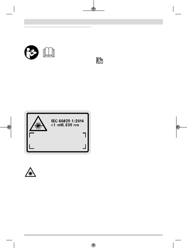
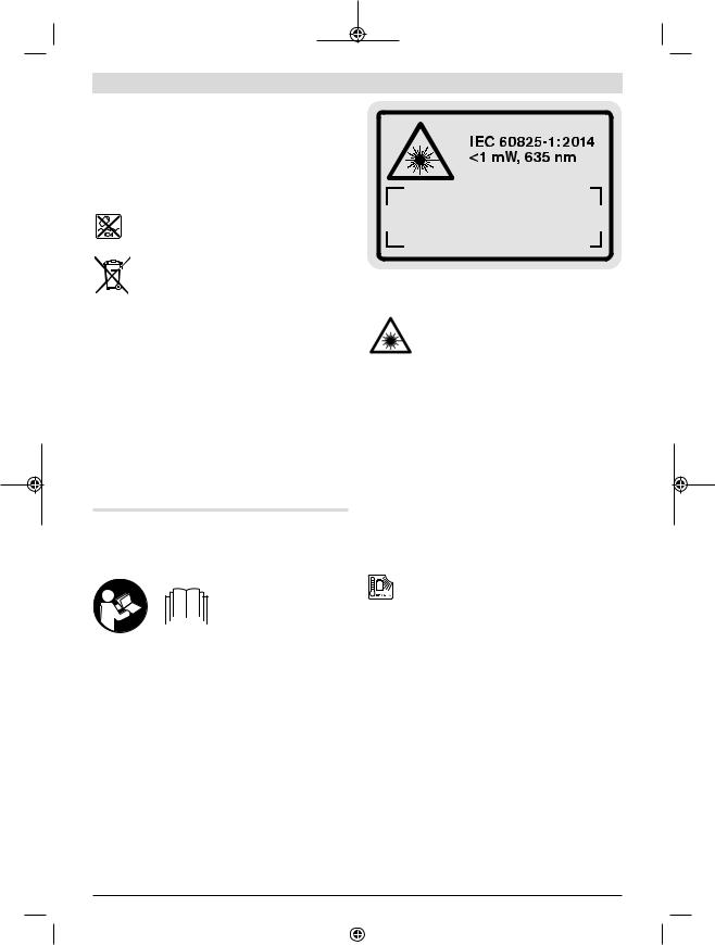
The measuring tool is delivered with a warning label (marked in the illustration of the measuring tool on the graphics page with number (20)).
Laser Radiation
Do not stare into beam
Class 2 laser product
uIf the text on the warning label is not in your native language, cover it with the label supplied, which is in your language, before initial commissioning.
Do not direct the laser beam at persons or animals and do not look directly into the laser beam or at its reflection. Doing so
could lead to blindless, or could cause acci-
dents or damage to the eyes.
uIf laser radiation hits your eye, you must close your eyes and immediately turn your head away from the beam.
uDo not make any modifications to the laser equipment.
uDo not use the laser goggles as protective goggles.
The laser goggles make the laser beam easier to see; they do not protect you against laser radiation.
uDo not use the laser goggles as sunglasses or while driving. The laser goggles do not provide full UV protection and impair your ability to see colours.
uHave the measuring tool serviced only by a qualified
specialist using only original replacement parts. This
will ensure that the safety of the measuring tool is main-
tained.
uDo not let children use the laser measuring tool unsupervised. They could accidentally dazzle someone.
uDo not use the measuring tool in explosive atmospheres which contain flammable liquids, gases or dust. Sparks may be produced inside the measuring tool, which can ignite dust or fumes.
Protect the measuring tool against heat, e.g. including prolonged sun exposure, fire, water, and moisture. Danger of explosion.
uThe battery may give off fumes if it becomes damaged or is used incorrectly. Ensure the area is well ventilated and seek medical attention should you experience any adverse effects. The fumes may irritate the respiratory system.
Product Description and
Specifications
Intended Use
The measuring tool is intended for measuring distances, lengths, heights, clearances and inclines, and for calculating areas and volumes.
The measuring tool is suitable for indoor and outdoor use.
Product features
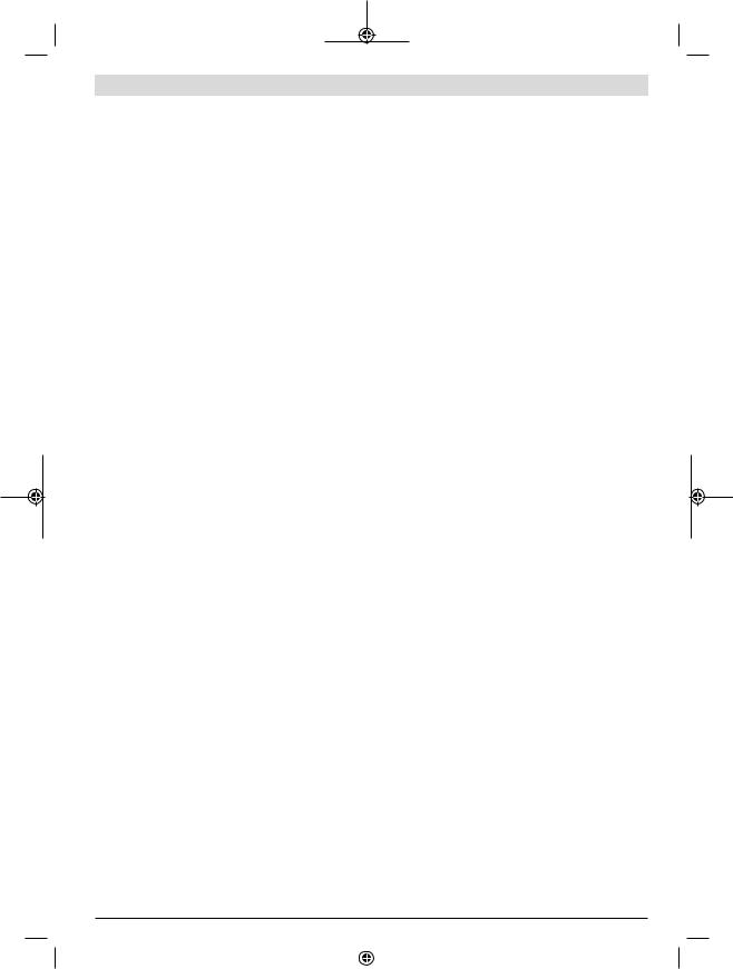
The numbering of the product features refers to the diagram of the measuring tool on the graphics page.
(1)Display
(2)Measuring button
(3)Button for grade measurement/calibrationA)
(4)Button for changing function/basic settingsA)
(5)Minus button
(6)Button for results/timer functionA)
(7)Button for list of measured values/saving constantA)
(8)Button for memory deletion/switching on or offA)
(9)Measuring pin
(10)Reference level selection button
(11)Plus button
(12)Button for distance, area and volume measurement
(13)Charging socket cover
(14)Socket for charging connector
(15)Carrying strap lug
(16)Laser beam output
(17)Reception lens
(18)Serial number
(19)1/4" thread
(20)Laser warning label
(21)Charging connector
1 609 92A 4R8 | (13.02.2019) |
|
|
|
Bosch Power Tools |
|
|
|
|
|
|
|
|
|
|
|
|
|
|
|
|
|
|
|
(22)Micro USB cable
(23)Protective bag
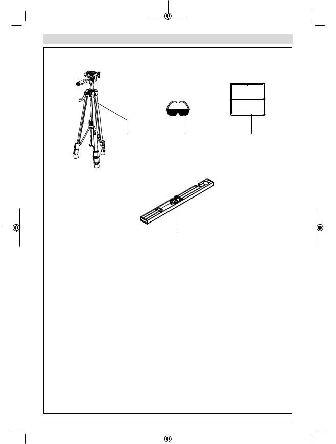
(24)Measuring railB)
(25)Locking lever for measuring barB)
(26)TripodB)
(27)Laser viewing glassesB)
(28)Laser target plateB)
A)Press and hold a button to activate its additional function.
B)Accessories shown or described are not included with the product as standard.
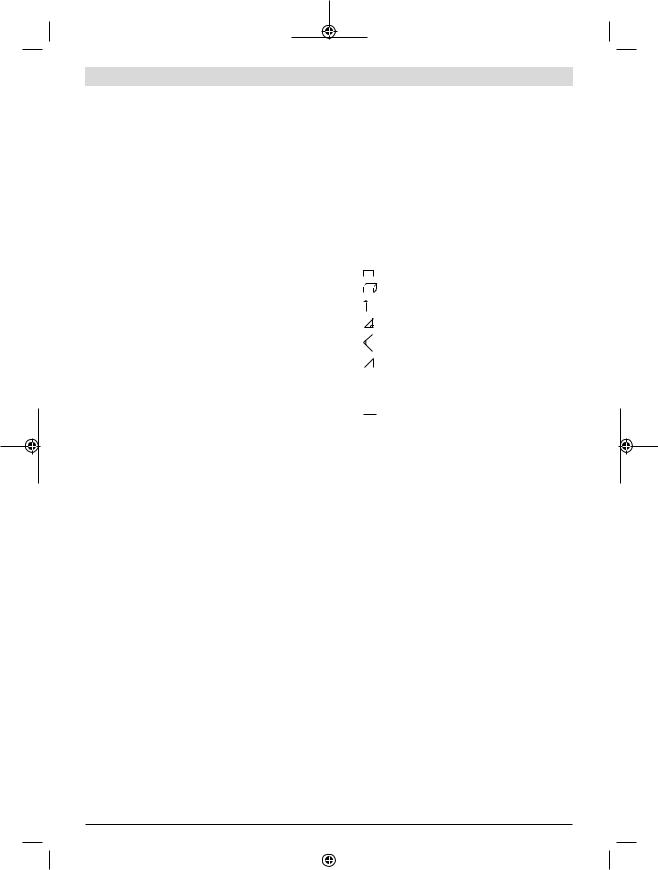
Display elements
(a)Measured value lines
(b)"ERROR" indicator
(c)Result line
(d)Digital spirit level/position of measured value list entry
(e)Indicator for measured value list
English | 9
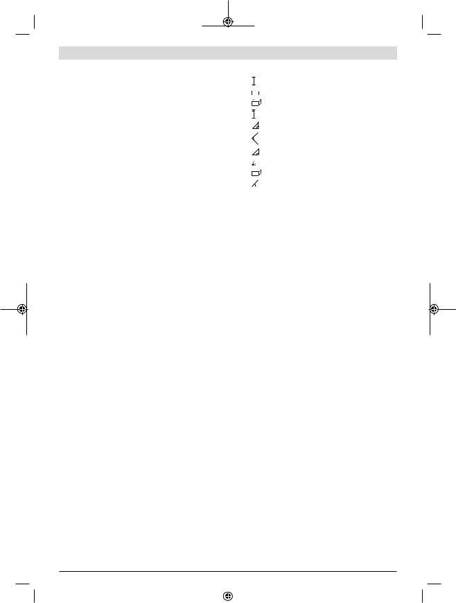
(f) Measuring functions
Length measurement
Area measurement
Volume measurement
Continuous measurement
|
1 |
Indirect height measurement |
|
|
|
1 |
|
Double indirect height measurement |
|
|
|
2 |
|
|
|
1 |
Indirect length measurement |
|
|
|
|
|
Timer function |
|
|
Wall area measurement |
|
|
Grade measurement |
(g)Battery charge indicator
(h)Laser switched on
(i)Reference level of measurement
(j)Temperature warning
Technical data
Digital laser measure |
GLM 100 |
GLM 100+R 60 |
Article number |
3 601 K72 P.. |
3 601 K72 P.. |
Distance measurement |
|
|
Measuring range (maximum) |
100 m A) |
100 m A) |
Measuring range (typical) |
0.05–80 m B) |
0.05–80 m B) |
Measuring range (typical, unfavourable conditions) |
35 m C) |
35 m C) |
Measuring accuracy (typical) |
± 1.5 mm B) |
± 1.5 mm B) |
Measuring accuracy (typical, unfavourable conditions) |
±2.5 mm C) |
±2.5 mm C) |
Smallest display unit |
0.1 mm |
0.1 mm |
Indirect distance measurement and level |
|
|
Measuring range |
-60° to +60° |
-60° to +60° |
Grade measurement |
|
|
Measuring range |
0°–360° (4 x 90°) D) |
0°–360° (4 x 90°) D) |
Measuring accuracy (typical) |
0.2° E) F) |
±0.2° E) F) |
Smallest display unit |
0.1° |
0.1° |
General |
|
|
Operating temperature |
-10 °C to +50 °C G) |
-10 °C to +50 °C G) |
Storage temperature |
-20 °C to +50 °C |
-20 °C to +50 °C |
Permitted charging temperature range |
+5 °C to +40 °C |
+5 °C to +40 °C |
Relative air humidity max. |
90% |
90% |
Max. altitude |
2000 m |
2000 m |
Pollution degree according to IEC 61010-1 |
2 H) |
2 H) |
Laser class |
2 |
2 |
Laser type |
635 nm, < 1 mW |
635 nm, < 1 mW |
Laser beam diameter (at 25 °C) approx. |
|
|
– 10 m distance |
6 mm F) |
6 mm F) |
– 80 m distance |
48 mm F) |
48 mm F) |
Adjustment accuracy of the laser to the housing approx. |
|
|
Bosch Power Tools |
|
|
|
1 609 92A 4R8 | (13.02.2019) |
|
|
|
|
|
|
|
|
|
|
|
|
|
|
|
|
|
|
|

10 | English
Digital laser measure |
GLM 100 |
GLM 100+R 60 |
|
– |
Vertical |
±2 mm/m I) |
±2 mm/m I) |
– |
Horizontal |
±10 mm/m I) |
±10 mm/m I) |
Automatic switch-off after approx. |
|
|
|
– |
Laser |
20 s |
20 s |
– Measuring tool (without measurement) |
5 min |
5 min |
|
Weight according to EPTA-Procedure 01:2014 |
0.14 kg |
0.14 kg |
|
Dimensions |
51 x 111 x 30 mm |
51 x 111 x 30 mm |
|
Protection rating |
IP 54 (dust and splash-proof) |
IP 54 (dust and splash-proof) |
|
Measuring rail |
|
|
|
Article number |
– |
3 601 K79 000 |
|
Dimensions |
– |
58 x 610 x 30 mm |
|
Battery |
Li-ion |
Li-ion |
|
Rated voltage |
3.7 V |
3.7 V |
|
Capacity |
1.25 Ah |
1.25 Ah |
|
Number of battery cells |
1 |
1 |
|
Individual measurements per battery charge approx. |
25000 J) |
25000 J) |
|
A)For distances greater than 80 m, we recommend using a retroreflective target plate (accessory).
B)For measurements from the front edge of the measuring tool, 100% reflectivity of the target (e.g. a white wall), weak backlighting and 25 °C operating temperature. In addition, a deviation influence of ± 0.05 mm/m needs to be taken into account.
C)For measurements from the rear edge of the measuring tool, 10–100 % reflectivity of the target, strong backlighting and 25 °C operating temperature. In addition, a deviation influence of ± 0.29 mm/m needs to be taken into account.
D)For measurements that use the back of the device as a reference, the max. measuring range amounts to ± 60°
E)After calibration in accordance with figure H. Additional pitch error of ± 0.01°/degree up to 45°.
F)The width of the laser line depends on the surface characteristics and on the ambient conditions.
G)In continuous measurement mode, the max. operating temperature is +40 °C.
H)Only non-conductive deposits occur, whereby occasional temporary conductivity caused by condensation is expected.
I)At 25 °C
J)For a new and charged battery without display illumination and sound.
The serial number (18) on the type plate is used to clearly identify your measuring tool.
Assembly
Battery charging
The battery can be charged from a USB port or USB power
supply (min. 500 mA) by using the micro USB cable.
Recommendations for optimal handling of the battery
do not leave it in a car for extended periods of time. In case of large variations in temperature, allow the measuring tool to adjust to the ambient temperature before putting it into operation. The precision of the measuring tool may be compromised if exposed to extreme temperatures or variations in temperature.
u Avoid substantial knocks to the measuring tool and
Only store the battery in the permitted temperature range (see "Technical data"). Do not leave the battery in your car in the summer, for example.
A significantly reduced operating time after charging indicates that the battery has deteriorated and must be replaced.
Follow the instructions on correct disposal.
Operation
Start-Up
uProtect the measuring tool from moisture and direct sunlight.
uDo not expose the measuring tool to any extreme temperatures or variations in temperature. For example,
avoid dropping it. Always carry out an accuracy check before continuing work if the measuring tool has been subjected to severe external influences (see "Checking accuracy and calibrating the grade measurement (see figure H)", page 14) and (see "Accuracy check of the distance measurement", page 14).
Switching on/off
uNever leave the measuring tool unattended when switched on, and ensure the measuring tool is switched off after use. Others may be dazzled by the laser beam.
The following options are available for switching on the measuring tool:
1 609 92A 4R8 | (13.02.2019) |
|
|
|
Bosch Power Tools |
|
|
|
|
|
|
|
|
|
|
|
|
|
|
|
|
|
|
|
–Pressing the on/off button (8): The measuring tool is switched on in the length measurement function. The laser is not switched on.
–Pressing the measuring button (2): Measuring tool and laser are switched on. The measuring tool will be in the length measurement function. When the measuring tool is inserted in the measuring rail (24), the grade measurement function is activated.
uDo not direct the laser beam at persons or animals and do not stare into the laser beam yourself (even from a distance).
To switch off the measuring tool, press and hold the on/off button (8).
If no button on the measuring tool is pressed for approx. five minutes, then the measuring tool will automatically switch itself off to preserve battery life.
If the angle has not been changed for approx. five minutes while the measuring tool is in the "grade measurement" operating mode, the tool will automatically switch itself off to preserve battery life.
All saved values are retained when the tool is automatically switched off.
Measuring process
After the measuring tool has been switched on by pressing the measuring button (2), the tool is always in the length measurement function by default, or in the grade measurement function if the tool has been inserted into the measuring rail (24). Other measuring functions can be switched to by pressing the respective function button (see "Measuring functions", page 12).
Once the measuring tool has been switched on, the rear edge of the measuring tool is selected as the reference level for measurement. You can change the reference level by pressing the reference level selection button(10) (see "Selecting the reference level (see figure A)", page 11).
Apply the measuring tool with the selected reference level to the point at which you want to start the measurement (e.g. wall).
To switch on the laser beam, briefly press the measuring button (2).
uDo not direct the laser beam at persons or animals and do not stare into the laser beam yourself (even from a distance).
Aim the laser beam at the target surface. To initiate the measurement, briefly press the measuring button (2) again. While the laser beam is continuously switched on, measurement will begin after the first press of the measuring button
(2). In the continuous measurement function, measurement begins as soon as the function is activated.
The measured value typically appears within 0.5 seconds and no later than 4 seconds. The duration of the measurement depends on the distance, the lighting conditions and the reflective properties of the target surface. The end of the measurement is indicated by an audio signal. Upon completion of the measurement, the laser beam is automatically switched off.
English | 11
If no measurement has been performed within approx. 20 seconds of aim being taken, the laser beam is switched off automatically to preserve battery life.
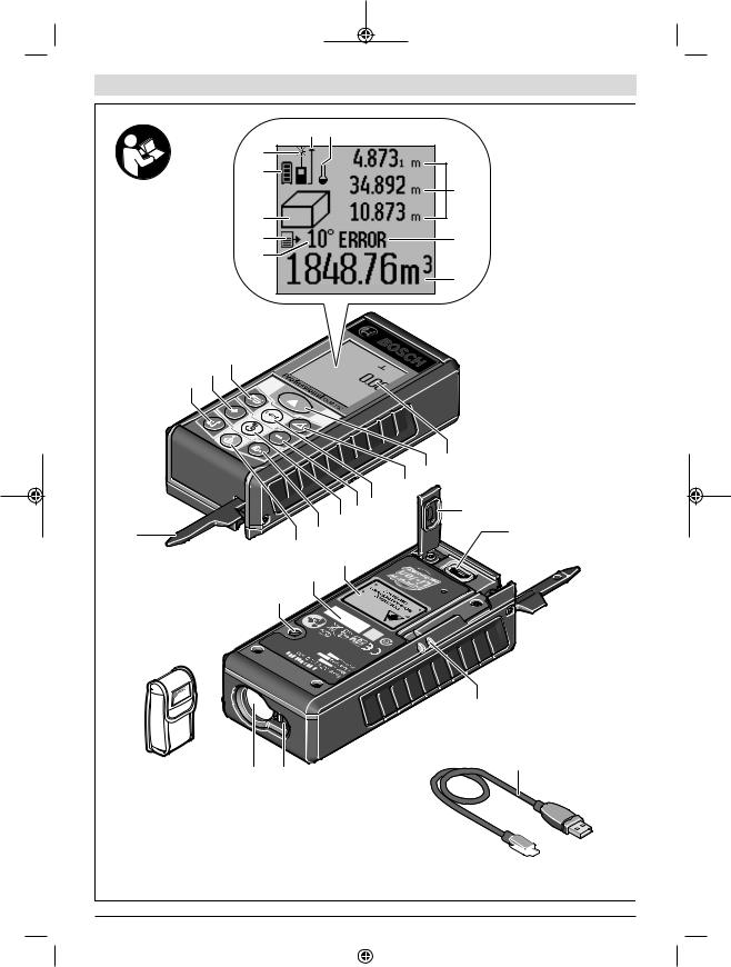
Selecting the reference level (see figure A)
You can choose between four different reference levels for the measurement:
–The rear edge of the measuring tool or the front edge of the measuring pin (9) when it has been folded out by 90° (e.g. when applying the tool to outer corners)
–The tip of the measuring pin (9) when it has been folded 180° (e.g. when measuring from a corner)
–The front edge of the measuring tool (e.g. when measuring from a table edge)
–The centre of the thread (19) (e.g. for tripod measurements)
To select the reference level, press the button (10) until the required reference level is shown on the display. The rear edge of the measuring tool is pre-set as the reference level every time the measuring tool is switched on.
It is not possible to make a retrospective alteration to the reference level for measurements that have already been taken (e.g. when displaying measured values in the measured value list).
Basic settings menu
To enter the basic settings menu, press and hold the button for basic settings (4).
Briefly press the basic settings button (4) to select the individual menu items.
Press the minus button (5) or the plus button (11) to select the setting within the menu items.
To exit the basic settings menu, press the measuring button
(2).
Basic settings
Audio signals |
On |
|
Off |
Display illumination |
On |
|
Off |
|
Automatically |
|
on/off |
Digital spirit level |
On |
|
Off |
Display rotation |
On |
Off
Bosch Power Tools |
|
|
|
1 609 92A 4R8 | (13.02.2019) |
|
|
|
|
|
|
|
|
|
|
|
|
|
|
|
|
|
|
|
On
Off
m, ft, inch, etc.
°, %, mm/m, inch/ft
All basic settings except for the continuous laser beam setting are saved when switching off the tool.
Continuous laser beam
uDo not direct the laser beam at persons or animals and do not stare into the laser beam yourself (even from a distance).
In this setting, the laser beam remains switched on even between measurements; measurement simply requires one brief press of the measuring button (2).
Measuring functions
Simple length measurement
For length measurements, repeatedly press the button (12) until the indicator for length measurement  appears on the display.
Briefly press the measuring button (2) once to switch on the laser and once to measure.
The measured value is displayed in the result line (c).
For multiple consecutive length measurements, the results of the last measurements are shown in the measured value lines (a).
Area measurement
For area measurements, repeatedly press the button (12) until the indicator for area measurement  appears on the display.
Then measure the width and length one after the other as with a length measurement. The laser beam remains switched on between the two measurements.
Once the second measurement has been completed, the area is automatically calculated and
displayed in the result line (c). The individual measured values can be found in the measured value lines (a).
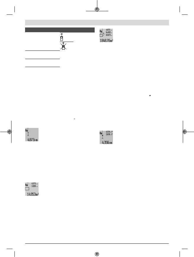
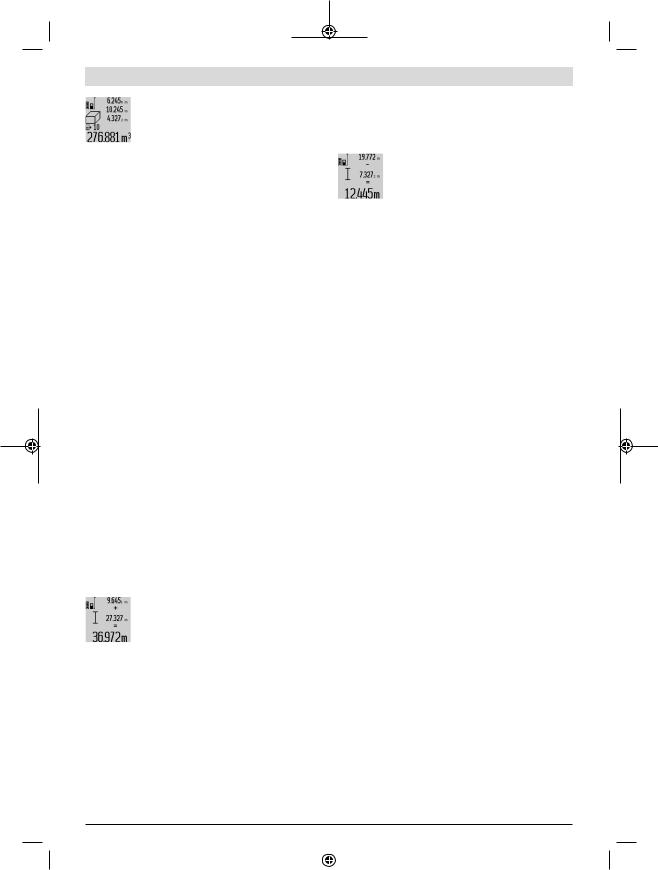
Volume measurement
For volume measurements, repeatedly press the button
(12) until the indicator for volume measurement  appears on the display.
Then measure the width, length and depth one after the other as with a length measurement. The laser beam remains switched on between the three measurements.
Once the third measurement has been completed, the volume is automatically calculated and displayed in the result line (c). The individual measured values can be found in the measured value lines (a).
Values over 999,999 m3 cannot be displayed; "ERROR" will instead appear on the display. Divide the volume to be measured into individual measurements, the resulting values of which you can calculate separately and then combine into an overall total.
Continuous measurement and minimum/maximum
measurement (see figure B)
In continuous measurement mode, the measuring tool can be moved relative to the target, during which the measured value will be updated every half a second. You can, for example, move a desired distance away from a wall while reading off the current distance at all times.
For continuous measurements, repeatedly press the button
for changing function (4) until the indicator  for continuous measurement appears on the display. To start the continuous measurement, press the measuring button (2).
The minimum measurement is used to determine the shortest distance from a fixed reference point. For example, it can help in determining verticals or horizontals.
The maximum measurement is used to determine the greatest distance from a fixed reference point. For example, it can help in determining diagonals.
The current measured value is shown in the result line (c). The maximum ("max") and minimum ("min") measured value appear in the measured value lines (a). It is then always overwritten if the current length measurement
value is smaller or larger than the previous minimum or maximum value.
Press the memory deletion button (8) to erase the previous minimum or maximum values.
Press the measuring button (2) to end the continuous measurement. The last measured value is displayed in the result line (c). Pressing the measuring button (2) again starts a new continuous measurement.
Continuous measurement automatically switches off after five minutes. The last measured value remains displayed in the result line (c).
Indirect distance measurement
The indirect distance measurement is used to determine distances that cannot be measured directly, due to an obstacle that would impede the path beam or the absence of a target surface that could serve as a reflector. This measuring procedure can only be employed vertically. Any horizontal deviation will lead to measurement errors.
The laser beam remains switched on between the individual measurements.
For indirect length measurements, three measuring modes are available. Each measuring mode can be used for determining different distances.
1 609 92A 4R8 | (13.02.2019) |
|
|
|
Bosch Power Tools |
|
|
|
|
|
|
|
|
|
|
|
|
|
|
|
|
|
|
|

a) Indirect height measurement (see figure C)
Repeatedly press the button for changing function (4) until
1
the indicator for indirect height measurement  appears on the display.
Ensure that the measuring tool is at the same height as the lower measuring point. Then tilt the measuring tool around the reference level and measure distance (1) as for a length measurement.
Once the measurement is complete, the result for the required distance "X" is displayed in the result line (c). The measured values for distance "1" and angle "α" can be found in the measured value lines (a).
b) Double indirect height measurement (see figure D)
Repeatedly press the button for changing function (4) until
1
the indicator for double indirect height measurement 2 appears on the display.
Measure distances "1" and "2" in succession as for a length measurement.
Once the measurement is complete, the result for the required distance "X" is displayed in the result line (c). The measured values for distances "1" and "2" and angle "α" can be found in the measured value lines (a).
Ensure that the reference level for the measurement (e.g. the rear edge of the measuring tool) remains in exactly the same place for all the individual measurements in a single measuring process.
a) Indirect length measurement (see figure E)
Repeatedly press the button for changing function (4) until the indicator for indirect length measurement 1  appears on the display.
Ensure that the measuring tool is at the same height as the required measuring point. Then tilt the measuring tool around the reference level and measure distance "1" as for a length measurement.
Once the measurement is complete, the result for the required distance "X" is displayed in the result line (c). The measured values for distance "1" and angle "α" can be found in the measured value lines (a).
Wall area measurement (see figure F)
The wall area measurement is used to determine the sum of multiple individual areas with a common height.
In the illustrated example, the total area of several walls that have the same ceiling height A but different lengths B is to be determined.
For wall area measurements, repeatedly press the button for changing function (4) until the indicator for wall area measurement  appears on the display.
Measure the ceiling height A as with a length measurement. The measured value ("cst") is displayed in the top measured value line (a). The laser remains switched on.
English | 13
Then measure the length B1 of the first wall. The area is automatically calculated and displayed in the result line (c). The last measured value for length can be found in the middle measured value line.(a). The laser remains
switched on.
Now measure the length B2 of the second wall. The individual measured value displayed in the middle measured value line (a) is added to the length B1. The sum of the two lengths ("sum", displayed in the bottom measured value line
(a)) is multiplied by the saved height A. The total area value is displayed in the result line (c).
You can measure any number of lengths Bx, which will be automatically added and multiplied by the height A.
The requirement for a correct area calculation is that the first measured length (for example the ceiling height A) is identical for all sub-areas.
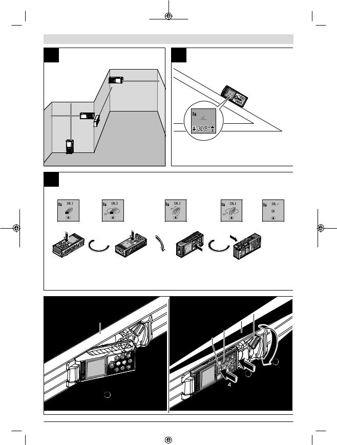
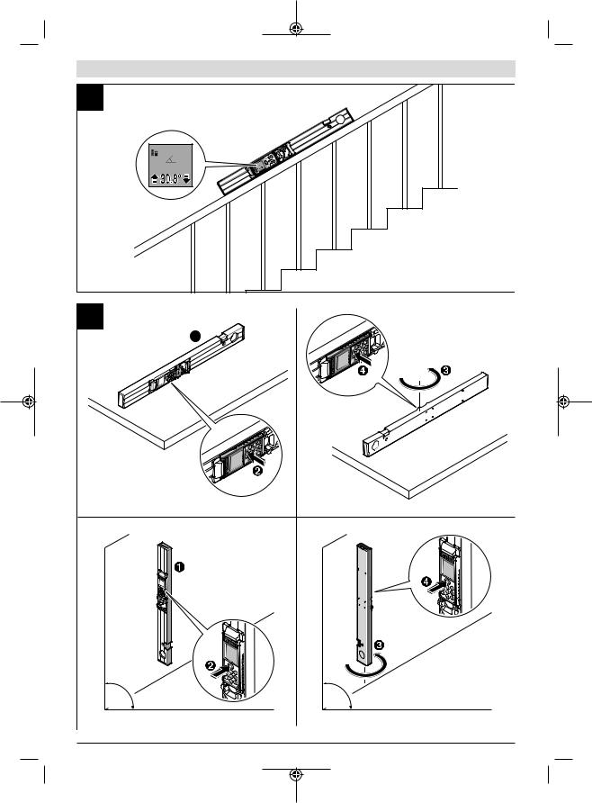
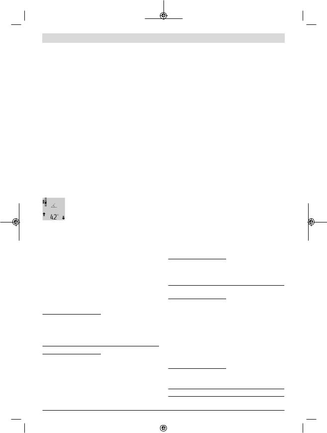
Grade measurement (see figure G)
Press the button for grade measurement (3) to bring up the indicator for grade measurement  on the display. The rear of the measuring tool serves as the reference level. Press the button for grade measurement (3) again to use the sides of the measuring tool as a reference level and rotate the display view by 90°.
Press the measuring button (2) to fix the measured value and transfer it to the measured value memory. Press the measuring button (2) again to continue the measurement. If the display flashes during measurement, the measuring tool has been tipped too heavily to the side.
If the "digital spirit level" function is activated in the basic settings, the grade value is also displayed in the other measuring functions in line (d) of the display (1).
Timer function
The timer function is useful when the measuring tool should be kept stationary during measurement, for example. Press and hold the button for the timer function (6) to bring up the indicator  on the display.
The time period between triggering the timer and starting measurement is displayed in the measured value line (a). The time period can be set between 1–60 seconds by pressing the plus button (11) or minus button (5).
The measurement is made automatically after the set time period has expired.
The timer function can also be used for distance measurements within other measuring
functions (e.g. area measurement). It is not possible to add or subtract measuring results or carry out continuous measurement.
List of the last measured values
The measuring tool stores the last 20 measured values and their calculations and displays them in reverse order (with the most recent measured value displayed first).
Bosch Power Tools |
|
|
|
1 609 92A 4R8 | (13.02.2019) |
|
|
|
|
|
|
|
|
|
|
|
|
|
|
|
|
|
|
|
14 | English
To retrieve the saved measurements, press the button (7). The result of the last measurement appears on the display, along with the indicator for the measured values list (e) and with storage space for the numbering of the dis-
played measurements.
If no further measurements are saved upon pressing the button (7) again, the measuring tool switches back to the last measuring function. Press one of the buttons for the measuring functions to exit the list of measured values.
To permanently save the currently displayed measured length value as a constant, press and hold the button for the list of measured values (7) until "CST" is shown on the display. An entry in the list of measured values cannot be retrospectively saved as a constant.
To use a measured length value in a measuring function (e.g. area measurement), press the button for the list of measured values (7), select the desired entry and confirm it by pressing the results button (6).
Deleting measured values
Briefly pressing the button (8) will delete the last measured value in all measuring functions. Repeatedly pressing the button briefly will delete the individual measured values in reverse order.
To delete the currently displayed entry in the list of measured values, briefly press the button (8). To delete the complete list of measured values and the constant "CST", press and hold the measured value list button (7) and at the same time briefly press the button (8).
In the wall area measurement function, a brief first press of the button (8) will delete the last individual measured value; a second press will delete all lengths BX; a third will delete the ceiling height A.
Adding measured values
To add measured values together, first perform any measurement or select an entry from the list of measured values. Next, press the plus button (11). "+" will appear on the display as confirmation. Then perform a second measurement or select another entry from the measured value list.
Press the results button (6) to retrieve the sum of both measurements. The calculation is shown in the measured value lines (a) and the sum is displayed in the result line (c).
When the sum has been calculated, you can add more measured values or measured value list entries to this result if you press the plus button (11) before each measurement. Press the results button (6) to end the addition.
Information on addition:
–Mixtures of length, area and volume values cannot be added together. For example, if a length value and an area value are added together, "ERROR" will appear briefly on the display when the results button (6) is pressed. The measuring tool will then switch back to the most recently active measuring function.
–The result of a measurement (e.g. volume value) is always added; for continuous measurements, the measured
value displayed in the result line (c) is added. It is not possible to add individual measured values from the measured value lines (a).
Subtracting measured values
To subtract measured values, press the minus button (5); "-" will appear on the display as confirmation. The subsequent steps are the same as for the "Adding measured values" section.
Practical advice
General advice
The reception lens (17) and the laser beam output (16) must not be covered during the measuring process.
The measuring tool must not be moved during a measurement (with the exception of the continuous measurement and grade measurement functions). For this reason, place the measuring tool against or on a firm surface whenever possible.
Influences on the measuring range
The measuring range depends on the lighting conditions and the reflective properties of the target surface. For better visibility of the laser beam when working outdoors and in bright sunlight, use the laser viewing glasses (27) (accessory) and the laser target plate (28) (accessory) or shade the target area.
Influences on the measurement result
Due to physical effects, the possibility of inaccurate measurements when measuring various surfaces cannot be excluded. These include:
–Transparent surfaces (e.g. glass, water)
–Reflective surfaces (e.g. polished metal, glass)
–Porous surfaces (e.g. insulating materials)
–Structured surfaces (e.g. roughcast, natural stone).
If necessary, use the laser target plate (28) (accessory) on these surfaces.
Inaccurate measurements are also possible where the laser is pointed at target surfaces diagonally.
Layers of air at different temperatures and indirectly received reflections can also influence the measured value.
Checking accuracy and calibrating the grade
measurement (see figure H)
Regularly check the accuracy of the grade measurement. This is accomplished by means of a reverse measurement. To do this, lay the measuring tool on a table and measure the inclination. Turn the measuring tool by 180° and measure the inclination again. The difference between the displayed values must not exceed 0.3°.
In case of greater deviation, the measuring tool must be recalibrated. To do this, press and hold the grade measurement button (3). Follow the directions on the display.
Accuracy check of the distance measurement
You can check the accuracy of the measuring tool as follows:
1 609 92A 4R8 | (13.02.2019) |
|
|
|
Bosch Power Tools |
|
|
|
|
|
|
|
|
|
|
|
|
|
|
|
|
|
|
|
–Choose a measuring section of approx. 1–10 m in length that is permanently unchanged, the exact length of which is known to you (e.g. room width, door opening). The measuring section must be indoors, and the target surface of the measurement must be smooth and reflect well.
–Measure the section ten times in succession.
The deviation between the individual measurements and the mean value must not exceed ± 2 mm. Record the measurements in order to be able to compare the accuracy later on.
Working with the tripod (accessory)
The use of a tripod is particularly necessary for larger distances. Place the measuring tool with the 1/4" thread (19) on the quick-release plate of the tripod (26) or a conventional camera tripod. Tighten it using the locking screw of the quick-release plate.
Set the reference level for measurements with a tripod by pressing the button (10) accordingly (thread reference level).
Working with the measuring rail (see figures I–K)
The measuring rail (24) can be used for a more exact grade measurement result. Distance measurements are not possible with the measuring rail.
Insert the measuring tool into the measuring rail (24) as shown and lock the measuring tool in place with the locking lever (25). Press the measuring button (2) to activate the "measuring rail" operating mode.
Regularly check the accuracy of the grade measurement by means of a reverse measurement or the levels on the measuring rail.
In case of greater deviation, the measuring tool must be recalibrated. To do this, press and hold the grade measurement button (3). Follow the directions on the display.
To end the "measuring rail" operating mode, switch off the measuring tool and remove it from the measuring rail.
Errors – Causes and Corrective Measures
Cause |
Corrective measures |
Temperature warning flashes, measurement not possible
The measuring tool is outside Wait until the measuring tool the operating temperature of has reached operating tem- -10 °C to +50 °C (in the conperature.
tinuous measurement function, up to +40 °C).
Display shows "ERROR"
Addition/subtraction of |
Only add/subtract measured |
measured values with differ- |
values with the same units of |
ent units of measurement. |
measurement. |
Angle between laser beam |
Increase the angle between |
and target is too acute. |
the laser beam and the target |
Target surface is too reflect- |
Use the laser target plate |
ive (e.g. mirror) or not re- |
(28). |
|
English | 15 |
|
|
Cause |
Corrective measures |
flective enough (e.g. black |
|
material), or ambient light is |
|
too bright. |
|
The laser beam output (16) |
Wipe the laser beam output |
and/or reception lens (17) |
(16) and/or reception lens |
are fogged up (e.g. due to a |
(17) dry with a soft cloth. |
rapid temperature change). |
|
Calculated value is larger |
Divide the calculation into in- |
than 999,999 m/m2/m3. |
termediate steps. |
Display shows "> 60°" or "< -60°" |
|
The grade measuring range |
Perform the measurements |
for the measuring function or |
within the specified angle |
reference level has been ex- |
range. |
ceeded. |
|
Display shows "CAL" and "ERROR" |
|
The calibration of the grade |
Repeat the calibration ac- |
measurement has not been |
cording to the instructions |
carried out in the right order |
that appear on the display |
or has not been carried out in |
and in the manual. |
the correct positions. |
|
The surfaces used for calib- |
Repeat the calibration on a |
ration were not precisely ho- |
horizontal or vertical surface |
rizontal or vertical. |
and check the surfaces be- |
|
forehand if necessary using a |
|
spirit level. |
The measuring tool has |
Repeat the calibration and |
moved or tilted when the |
hold the measuring tool still |
button was pressed. |
against the surface when |
|
pressing the button. |
Battery charge indicator (g), temperature warning (j)
and "ERROR" shown in the display
The temperature of the |
Wait until the charging tem- |
measuring tool is outside the |
perature range has been |
permissible charging temperreached. ature range.
Battery charge indicator (g) and "ERROR" shown in the display
The battery charging voltage |
Check whether the connec- |
is not correct. |
tion has been established |
|
correctly and that the micro |
|
USB cable is working prop- |
|
erly. If the device symbol |
|
flashes, the battery is defect- |
|
ive and must be replaced by |
|
the Bosch after-sales ser- |
|
vice. |
Battery charge indicator (g) and clock symbol (f) shown in the display
Charging time significantly Only use the original Bosch extended due to the charging micro USB cable.
current being too low.
Measurement result implausible
Bosch Power Tools |
|
|
|
1 609 92A 4R8 | (13.02.2019) |
|
|
|
|
|
|
|
|
|
|
|
|
|
|
|
|
|
|
|
16 | English
Cause |
Corrective measures |
Target surface reflection not |
Cover the target surface. |
distinct (e.g. water, glass). |
|
Laser beam output (16) and/ |
Keep the laser beam output |
or reception lens (17) are |
(16) and/or reception lens |
covered. |
(17) clear. |
An incorrect reference level |
Select a reference level that |
has been set. |
is appropriate for the meas- |
|
urement. |
Obstruction in the path of the The laser point must be fully
laser beam. on the target surface.
The indicator remains unchanged or the measuring tool
reacts unexpectedly when a button is pressed.
Software error. |
Press the measuring button |
|
(2) and the button for |
|
memory deletion/switching |
|
on or off (8) to reset the soft- |
|
ware. |
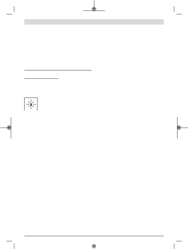
The measuring tool monitors correct functioning in every measurement. If a defect is detec-
ted, the display will indicate only the symbol shown opposite. In this case, or if the abovementioned corrective measures cannot rectify
an error, submit the measuring tool to the Bosch after-sales service via your dealer.
Maintenance and Service
Maintenance and Cleaning
Only store and transport the measuring tool in the protective bag provided.
Keep the measuring tool clean at all times.
Never immerse the measuring tool in water or other liquids. Wipe off any dirt using a damp, soft cloth. Do not use any detergents or solvents.
Take particular care of the reception lens (17), which must be handled with the same level of care you would give to a pair of glasses or a camera lens.
If the measuring tool needs to be repaired, send it off in the protective bag (23).
After-Sales Service and Application Service
Our after-sales service responds to your questions concerning maintenance and repair of your product as well as spare parts. You can find explosion drawings and information on spare parts at: www.bosch-pt.com
The Bosch product use advice team will be happy to help you with any questions about our products and their accessories.
In all correspondence and spare parts orders, please always include the 10 digit article number given on the nameplate of the product.
Great Britain
Robert Bosch Ltd. (B.S.C.)
P.O. Box 98
Broadwater Park
North Orbital Road
Denham Uxbridge
UB 9 5HJ
At www.bosch-pt.co.uk you can order spare parts or arrange the collection of a product in need of servicing or repair. Tel. Service: (0344) 7360109
E-Mail: boschservicecentre@bosch.com
Ireland
Origo Ltd.
Unit 23 Magna Drive
Magna Business Park
City West
Dublin 24
Tel. Service: (01) 4666700
Fax: (01) 4666888
Australia, New Zealand and Pacific Islands
Robert Bosch Australia Pty. Ltd.
Power Tools
Locked Bag 66
Clayton South VIC 3169
Customer Contact Center
Inside Australia:
Phone: (01300) 307044
Fax: (01300) 307045
Inside New Zealand:
Phone: (0800) 543353
Fax: (0800) 428570
Outside AU and NZ:
Phone: +61 3 95415555
www.bosch-pt.com.au
www.bosch-pt.co.nz
Republic of South Africa
Customer service
Hotline: (011) 6519600
Gauteng – BSC Service Centre
35 Roper Street, New Centre
Johannesburg
Tel.: (011) 4939375
Fax: (011) 4930126
E-mail: bsctools@icon.co.za
KZN – BSC Service Centre
Unit E, Almar Centre
143 Crompton Street
Pinetown
Tel.: (031) 7012120
Fax: (031) 7012446
E-mail: bsc.dur@za.bosch.com
Western Cape – BSC Service Centre
Democracy Way, Prosperity Park
Milnerton
Tel.: (021) 5512577
Fax: (021) 5513223
E-mail: bsc@zsd.co.za
1 609 92A 4R8 | (13.02.2019) |
|
|
|
Bosch Power Tools |
|
|
|
|
|
|
|
|
|
|
|
|
|
|
|
|
|
|
|
| 17
Bosch Headquarters
Midrand, Gauteng
Tel.: (011) 6519600
Fax: (011) 6519880
E-mail: rbsa-hq.pts@za.bosch.com
Disposal
Measuring tools, rechargeable/non-rechargeable batteries, accessories and packaging should be sorted for environmental-friendly recycling.
Do not dispose of the measuring tools or re- chargeable/non-rechargeable batteries with household waste.
Batteries:
uIntegrated batteries may only be removed for disposal by qualified personnel. Opening the housing shell can destroy the measuring tool.
Discharge the battery completely. Unscrew all screws on the housing and open the housing shell. Disconnect the connections at the battery and take out the battery.
Do not dispose of the batteries by throwing them out with household waste, on a fire or into water. After running down their charge (where possible), batteries should be collected and recycled or disposed of in an environmentally friendly manner.


u–
示意图中用编号(20)
Laser Radiation
Do not stare into beam
Class 2 laser product
u 戒牌上。
目、引发事故或损伤眼睛。
u 从光束位置将头移开。
彩的感知。
u 测量仪。
u 仪。
u 燃粉尘和气体。
的危险。
u 会刺激呼吸道。
(3)/ A)
(4)/ A)
Bosch Power Tools |
|
|
|
1 609 92A 4R8 | (13.02.2019) |
|
|
|
|
|
|
|
|
|
|
|
|
|
|
|
|
|
|
|
18 |
(6)/ A)
(7)/ A)
(8)/ A)
(19)1/4
(22)Micro USB
(24)B)
(25)B)
(26)B)
(27)B)
(28) B)
B) 中。
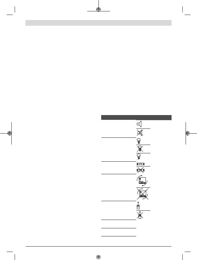
(b)“Error”
(d)/
|
|
|
|
|
|
|
|
|
|
|
|
|
|
|
|
|
|
|
|
1 |
|
||
2 |
|
|
|
1 |
|
|
|
1 


|
GLM 100 |
GLM 100+R 60 |
|
3 601 K72 P.. |
3 601 K72 P.. |
|
|
|
|
100 A) |
100 A) |
|
0.05-80 B) |
0.05-80 B) |
|
35 C) |
35 C) |
|
±1.5 B) |
±1.5 B) |
|
±2.5 C) |
±2.5 C) |
|
0.1 |
0.1 |
|
|
|
|
–60 +60 |
–60 +60 |
|
|
|
|
0 –360 4x90 D) |
0 –360 4x90 D) |
|
0.2 E) F) |
±0.2 E) F) |
|
0.1 |
0.1 |
|
|
|
|
–10 +50 G) |
–10 +50 G) |
|
–20 +50 |
–20 +50 |
|
+5 +40 |
+5 +40 |
1 609 92A 4R8 | (13.02.2019) |
|
|
|
Bosch Power Tools |
|
|
|
|
|
|
|
|
|
|
|
|
|
|
|
|
|
|
|
|
|
| 19 |
|
|
|
|
GLM 100 |
GLM 100+R 60 |
|
90 % |
90 % |
|
2000 |
2000 |
IEC 61010-1 |
2 H) |
2 H) |
|
2 |
2 |
|
635 < 1 |
635 < 1 |
25 |
|
|
– 10 |
6 F) |
6 F) |
– 80 |
48 F) |
48 F) |
|
|
|
– |
±2 / I) |
±2 / I) |
– |
±10 / I) |
±10 / I) |
|
|
|
– |
20 |
20 |
– |
5 |
5 |
EPTA-Procedure 01:2014 |
0.14 |
0.14 |
|
51 x 111 x 30 |
51 x 111 x 30 |
|
IP 54 |
IP 54 |
|
|
|
|
– |
3 601 K79 000 |
|
– |
58 x 610 x 30 |
|
|
|
|
3.7 |
3.7 |
|
1.25 |
1.25 |
|
1 |
1 |
|
25000 J) |
25000 J) |
A)80
B)100 % 25±0.05 /
C)10 –100 % 25 ±0.29/
D)±60
E)H ±0.01 / 45
G)+40
I)25
(18)
|
|
|
|
|
|
USB USB 500 |
|
Micro USB |
|
|
|
“ |
u |
” |
|
|
|
Bosch Power Tools |
|
|
|
1 609 92A 4R8 | (13.02.2019) |
|
|
|
|
|
|
|
|
|
|
|
|
|
|
|
|
|
|
|
20 |
u 一次精度检查( “H ”, 23) ( “”, 23)
/
u 可能会让旁人炫目。
–(8)
–(2) (24)
u 作。
(8)5 “ ” 5
(2)(24)( “ ”, 21)
准面按键(10) ( “
A ”, 20)
(2)
压测量按键(2) (2)0.5 420
A
–90 (9)
–180 (9)
– 时
–(19) (10)
“ ”
“ ”
(4)
(4)(5) (11)
“ ” (2)
|
|
|
|
|
|
|
|
|
|
|
/ |
|
|
|
|
|
|
|
|
|
|
|
|
|
|
|
|
|
% / |
|
/ |
1 609 92A 4R8 | (13.02.2019) |
|
|
|
Bosch Power Tools |
|
|
|
|
|
|
|
|
|
|
|
|
|
|
|
|
|
|
|
“ ”
u 作。
(2)
(12)
按压测量按键(2)(c)
(a)
(12)
显示在结果行(c)(a)
(12)
显示在结果行(c)(a)
999 999“ERROR”
/ / B
0.5 (4)
 (2)
(2)
(c)(a) “max”“min”
| 21
会被新的测量值取代。 按下存储器删除按键(8)(2) (c)(2)5 (c)
有障碍物阻挡了光路或者没有目标表面可以充当反 射体时。该测量方法只适用于垂直方向。任何水平 方向的偏差都会导致测量错误。
的功能可以确定不同的线段。
a) C
(4)1  (1)
(1)
(c)“X” “1” “α”(a)
b) D
(4)
1
2“1” “2”
(c)“X” “1”“2” “α”(a)
完全相同的位置。
c) E
(4)1  “1”
“1”
(c)“X” “1” “α”(a)
F
在图示的例子中要测定空间高度A B(4)
Bosch Power Tools |
|
|
|
1 609 92A 4R8 | (13.02.2019) |
|
|
|
|
|
|
|
|
|
|
|
|
|
|
|
|
|
|
|
Loading...