


 Loading...
GLM 150 C Professional
Robert Bosch Power Tools GmbH
70538 Stuttgart
GERMANY
www.bosch-pt.com
1 609 92A 62J (2020.09) O / 71
1 609 92A 62J
en Original instructions zh ko
th
id Petunjuk-Petunjuk untuk
Penggunaan Orisinal
vi Bản gốc hướng dẫn sửdụng

2 |
English ................................................... |
Page |
10 |
.................................................. |
19 |
|
............................................... |
28 |
|
...................................................... |
37 |
|
Bahasa Indonesia..................................... |
Halaman |
49 |
Tiếng Việt ............................................... |
Trang |
58 |
1 609 92A 62J | (22.09.2020) |
|
|
|
Bosch Power Tools |
|
|
|
|
|
|
|
|
|
|
|
|
|
|
|
|
|
|
|

| 3
(d)(e) (f)(g) (h)
05.05.2017
7:26:12
(c) |
30º |
8.179 M |
(b) |
|
9.273 M |
|
13.919 M |
|
|
|
18.558M |
(a) |
|
23.198M |
(j) |
(i) |
(o) |
|||||
|
|
|
|
|
|
|
|
|
|
|
Settings |
|
|
Tool Settings |
|
Length |
Bluetooth |
Language |
|||||
CAL
CAL
(k) |
(j) |
(i) |
(m) |
(l) |
(n) |
(2)
(13)
(12)
(11)
(10)
(9)
 (1)
(1)
(2)
(3)
(4)
(6)(5)
(7)
(8) |
(16) |
(15)
(14)
 (23)
(23)
(24) |
(21) |
(20) |
(17) |
|
(19) |
|
(18) |
GLM 150 C |
(22) |
|
Bosch Power Tools |
|
|
|
1 609 92A 62J | (22.09.2020) |
|
|
|
|
|
|
|
|
|
|
|
|
|
|
|
|
|
|
|
4 |
A
B |
1 |
|
1 |
|
X |
1 609 92A 62J | (22.09.2020) |
Bosch Power Tools |

|
| 5 |
C |
|
|
1 |
|
2 |
|
1 |
|
X |
|
2 |
D |
1 |
|
1 |
|
X |
Bosch Power Tools |
1 609 92A 62J | (22.09.2020) |
6 | |
|
|
E |
|
|
2 |
1 |
3 |
|
|
|
|
|
3 |
|
|
2 |
|
|
90° |
|
|
1 |
F |
|
|
|
|
L 3 |
|
|
L1 |
|
|
L 2 |
|
|
H |
1 609 92A 62J | (22.09.2020) |
Bosch Power Tools |
|
|
|
|
|
| 7 |
G |
|
|
|
|
|
|
|
|
2X 0.500M |
|
|
|
|
1.000 M |
|
|
1 |
|
|
1 |
|
|
|
|
X |
|
|
|
|
|
0,5 |
M |
||
|
|
|
||
2 |
|
|
|
|
|
X |
|
|
|
|
|
0,5 |
M |
|
|
|
|
|
|
Bosch Power Tools |
|
|
|
1 609 92A 62J | (22.09.2020) |
|
|
|
|
|
|
|
|
|
|
|
|
|
|
|
|
|
|
|
8 |
H
1 609 92A 62J | (22.09.2020) |
|
|
|
Bosch Power Tools |
|
|
|
|
|
|
|
|
|
|
|
|
|
|
|
|
|
|
|
| 9
2 607 001 391
1 608 M00 05B
BT 150
0 601 096 B00
Bosch Power Tools |
|
|
|
1 609 92A 62J | (22.09.2020) |
|
|
|
|
|
|
|
|
|
|
|
|
|
|
|
|
|
|
|
10 | English
English
Safety Instructions
All instructions must be read and observed in order for the measuring tool to function safely. The safeguards integrated into the measuring tool may be compromised if the
measuring tool is not used in accordance with these instructions. Never make warning signs on the measuring tool unrecognisable. SAVE THESE INSTRUCTIONS FOR FUTURE REFERENCE AND INCLUDE THEM WITH THE MEASURING TOOL WHEN TRANSFERRING IT TO A THIRD PARTY.
uWarning! If operating or adjustment devices other than those specified here are used or other procedures are carried out, this can lead to dangerous exposure to radiation.
uThe measuring tool is delivered with a laser warning sign (marked in the illustration of the measuring tool on the graphics page).
uIf the text of the laser warning label is not in your national language, stick the provided warning label in your national language over it before operating for the first time.
Do not direct the laser beam at persons or animals and do not stare into the direct or reflected laser beam yourself. You could
blind somebody, cause accidents or damage
your eyes.
uIf laser radiation hits your eye, you must close your eyes and immediately turn your head away from the beam.
uDo not make any modifications to the laser equipment.
uDo not use the laser goggles (accessory) as protective goggles. The laser goggles make the laser beam easier to see; they do not protect you against laser radiation.
uDo not use the laser goggles (accessory) as sunglasses or while driving. The laser goggles do not provide full UV protection and impair your ability to see colours.
uHave the measuring tool serviced only by a qualified specialist using only original replacement parts. This will ensure that the safety of the measuring tool is maintained.
uDo not let children use the laser measuring tool unsupervised. They could accidentally dazzle someone.
uDo not use the measuring tool in explosive atmospheres which contain flammable liquids, gases or dust. Sparks may be produced inside the measuring tool, which can ignite dust or fumes.
uThe measuring tool is equipped with a wireless interface. Local operating restrictions, e.g. in aeroplanes or hospitals, must be observed.
The Bluetooth® word mark and logos are registered trademarks owned by Bluetooth SIG, Inc. and any use of such marks by Robert Bosch Power Tools GmbH is under license.
uCaution! Using the measuring tool with Bluetooth® can cause faults to occur in other devices and systems, aeroplanes and medical devices (e.g. pacemakers, hearing aids). Also, damage to people and animals in the immediate vicinity cannot be completely excluded. Do not use the measuring tool with Bluetooth® in the vicinity of medical devices, petrol stations, chemical plants, areas with a potentially explosive atmosphere and in blasting areas. Do not use the measuring tool with Bluetooth® on aeroplanes. Avoid using the product near your body for extended periods.
Product Description and
Specifications
Please observe the illustrations at the beginning of this operating manual.
Intended Use
The measuring tool is intended for measuring distances, lengths, heights, clearances and inclines, and for calculating areas and volumes.
The measuring results can be transferred to other devices via Bluetooth®.
The measuring tool is suitable for indoor and outdoor use.
Product features
The numbering of the product features shown refers to the illustration of the measuring tool on the graphic page.
(1)Display
(2)Measuring button [ ] (can be used at the front or side)
(3)Soft key [ ]
]
(4)Plus button [+]/Select to the right
(5)Zoom button
(6)Carrying strap lug
(7)Measuring pin release button
(8)Measuring pin
(9)On/off/delete button [ ]
]
(10)Viewfinder button
(11)Minus button [–]/Select to the left
(12)Soft key [ ]
]
(13)Function button [Func]
(14)Laser warning label
(15)Serial number
(16)Battery compartment cover
(17)1/4" tripod socket
(18)Reception lens
1 609 92A 62J | (22.09.2020) |
|
|
|
Bosch Power Tools |
|
|
|
|
|
|
|
|
|
|
|
|
|
|
|
|
|
|
|
(19)Laser beam output
(20)Camera
(21)Rotary lock
(22)Batteries
(23)Protective bag
(24)Carrying strap
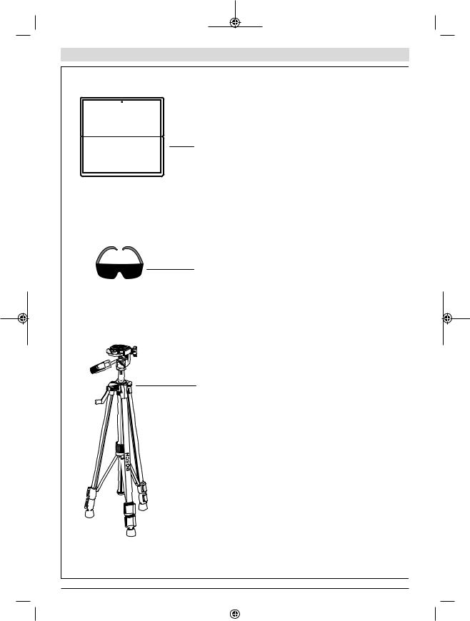
(25)Laser target plateA)
(26)Laser viewing glassesA)
(27)TripodA)
A)Accessories shown or described are not included with the product as standard. You can find the complete selection of accessories in our accessories range.
Display elements
(a)Result line
(b)Target display (crosshairs)
(c)Display tilt angle
(d)Date/time
(e)Reference level of measurement
(f)Connection status
Bluetooth® not activated
Bluetooth® activated, connection established
(g)Battery indicator
(h)Measured value lines
(i)Settings (soft key)
(j)Selected measuring function
(k)Internal memory (soft key)
(l)Integrated help function (soft key)
(m)Back (soft key)
(n)Start screen (soft key)
(o)Tool settings
Technical data
Digital laser |
GLM 150 C |
measure |
|
Article number |
3 601 K72 F.. |
Measuring range (typical) |
0.08–150 mA) |
Measuring range (typical, |
0.08–60 mB) |
unfavourable conditions) |
|
Measuring accuracy (typ- |
±1.5 mmA) |
ical) |
|
Measuring accuracy (typ- |
±3.0 mmB) |
ical, unfavourable condi- |
|
tions) |
|
Smallest display unit |
0.5 mm |
Indirect distance measurement and level |
|
Measuring range |
0°–360° (4 x 90°) |
Grade measurement |
|
|
|
English | 11 |
|
|
|
Digital laser |
GLM 150 C |
|
measure |
|
|
Measuring range |
0°–360° (4 x 90°) |
|
Measuring accuracy (typ- |
±0.2°C)D)E) |
|
ical) |
|
|
Smallest display unit |
0.1° |
|
General |
|
|
Operating temperature |
-10 °C to +45 °CF) |
|
Storage temperature |
-20 °C to +70 °C |
|
Permitted charging temper- |
+5 °C to +40 °C |
|
ature range |
|
|
Relative air humidity max. |
90% |
|
Max. altitude |
2000 m |
|
Pollution degree according |
2G) |
|
to IEC 61010-1 |
|
|
Laser class |
2 |
|
Laser type |
650 nm, < 1 mW |
|
Laser beam diameter (at 25 °C) approx. |
||
– |
10 m distance |
9 mm |
– |
100 m distance |
90 mm |
Automatic switch-off after approx. |
||
– |
Laser |
20 s |
– |
Measuring tool (without |
5 minH) |
|
measurement) |
|
Batteries |
3 x 1.5 V LR6 (AA) |
|
Weight according to EPTA- |
0.23 kg |
|
Procedure 01:2014 |
|
|
Dimensions |
142 (176) x 64 x 28 mm |
|
Protection rating |
IP 54 (dustand |
|
|
|
splash-proof) |
Data transmission |
|
|
Bluetooth® |
Bluetooth® |
|
|
|
(4.2 Low Energy)I) |
Operating frequency band |
2402–2480 MHz |
|
Bosch Power Tools |
|
|
|
1 609 92A 62J | (22.09.2020) |
|
|
|
|
|
|
|
|
|
|
|
|
|
|
|
|
|
|
|
12 | English
Digital laser |
GLM 150 C |
measure |
|
Max. transmission power |
8 mW |
A)For measurements from the front edge of the measuring tool, this applies for high reflectivity of the target (e.g. a whitepainted wall), weak backlighting and 25 °C operating temperature. In addition, a deviation of ±0.05 mm/m must be taken into account.
B)For measurements from the front edge of the measuring tool, this applies for high reflectivity of the target (e.g. a whitepainted wall), and strong backlighting. In addition, a deviation of ±0.15 mm/m must be taken into account.
C)After calibration at 0° and 90°. Additional pitch error of max. ±0.01°/degree up to 45°. The measurement accuracy refers to the three orientations of the grade measurement calibration, see figure H
D)At an operating temperature of 25 °C
E)The left-hand side of the measuring tool serves as the reference level for grade measurement.
F)In continuous measurement mode, the max. operating temperature is +40 °C.
G)non-conductive soiling only, whereby occasional temporary conductivity caused by condensation is expected
H)The automatic switch-off time can be adjusted (to two, five, ten minutes or never).
I)When using Bluetooth® Low Energy devices, it may not be possible to establish a connection depending on the model and operating system. Bluetooth® tools must support the GATT profile.
The serial number (15) on the type plate is used to clearly identify your measuring tool.
Fitting
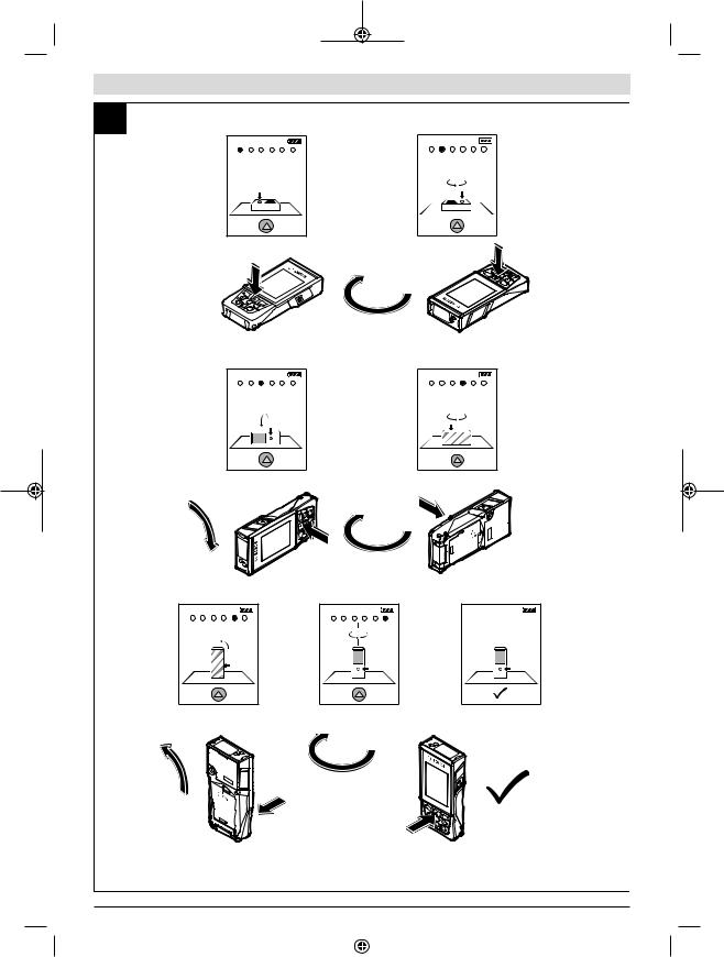
Inserting/Changing the Batteries
It is recommended that you use alkaline manganese batteries to operate the measuring tool.
–Press the release button (7) and fold the measuring pin
(8) out by 180°.
–To open the battery compartment cover (16), fold the rotary lock (21) upwards and turn it anti-clockwise by one quarter-turn. Lift up the battery compartment cover using the rotary lock. Insert the batteries. When inserting the batteries, ensure that the polarity is correct according to the illustration on the inside of the battery compartment.
uTake the batteries out of the measuring tool when you are not using it for a prolonged period of time. The batteries can corrode and self-discharge during prolonged storage.
uNote: TrackMyTools can only be used when batteries are inserted.
Operation
Start-Up
uNever leave the measuring tool unattended when switched on, and ensure the measuring tool is switched off after use. Others may be dazzled by the laser beam.
uProtect the measuring tool from moisture and direct sunlight.
uDo not expose the measuring tool to any extreme temperatures or variations in temperature. For example, do not leave it in a car for extended periods of time. In case of large variations in temperature, allow the measuring tool to adjust to the ambient temperature before putting it into operation. The precision of the measuring tool may be compromised if exposed to extreme temperatures or variations in temperature.
uAvoid substantial knocks to the measuring tool and avoid dropping it. Always carry out an accuracy check before continuing work if the measuring tool has been subjected to severe external influences (see "Accuracy check of the distance measurement", page 18).
uThe measuring tool is equipped with a wireless interface. Local operating restrictions, e.g. in aeroplanes or hospitals, must be observed.
Switching On/Off
During work, ensure that the reception lens (18), the laser beam output (19) and the camera (20) are not closed off or covered, otherwise correct measurement will not be possible.
–To switch on the measuring tool and the laser, briefly press the front or side measuring button (2) [ ].
].
–To switch on the measuring tool without the laser, briefly press the on/off/delete button (9) [ ].
].
uDo not direct the laser beam at persons or animals and do not stare into the laser beam yourself (even from a distance).
To switch off the laser, briefly press the on/off/delete button (9) [ ].
].
To switch off the camera, press the viewfinder button (10). To switch off the measuring tool, press and hold the on/off/ delete button (9) [ ].
].
The measured values and device settings in the memory are retained when you switch the measuring tool off.
Camera
The camera (20) is switched on automatically when the measuring tool is switched on for the first time. To switch it off, press the viewfinder button (10).
The camera setting (on/off) is saved when the measuring tool is switched off.
Optimising visibility of the laser point
Especially when using the measuring tool outdoors, in sunlight and also over long distances indoors, the laser point may not be visible. The visibility of the laser point/measurement point can additionally be improved in order to connect the camera by:
–Setting the display brightness (tool settings)
–Using the zoom by pressing the button (5).
1 609 92A 62J | (22.09.2020) |
|
|
|
Bosch Power Tools |
|
|
|
|
|
|
|
|
|
|
|
|
|
|
|
|
|
|
|
Measuring process
Once switched on, the measuring tool is in the length measurement function. For a different measuring function, press the [Func] button (13). Use the [+] button (4) or the [–] button (11) to select the required measuring function (see "Measuring functions", page 14). Activate the measuring function with the [Func] button (13) or with the measuring button (2) [ ].
].
Once the measuring tool has been switched on, the rear edge of the measuring tool is selected as the reference level for measurement. To change the reference level (see "Selecting the reference level (see figure A)", page 13). Apply the measuring tool to the point at which you want to start the measurement (e.g. wall).
Note: If the measuring tool has been switched on using the on/off/delete button (9) [ ], briefly press the measuring button (2) [
 ] to switch the laser on.
To initiate the measurement, briefly press the measuring button (2) [ ]. Afterwards, the laser beam is switched off. For a further measurement, repeat this process.
With the laser beam continuously switched on and when in the continuous measurement function, the measurement begins the first time you press the measuring button (2) [ ].
].
uDo not direct the laser beam at persons or animals and do not stare into the laser beam yourself (even from a distance).
Note: The measured value typically appears within half a second, and no later than approximately four seconds. The duration of the measurement depends on the distance, the lighting conditions and the reflective properties of the target surface. Upon completion of the measurement, the laser beam is automatically switched off. The continuously switched-on laser beam is not switched off after the measurement (see "Continuous laser beam", page 13).
Selecting the reference level (see figure A)
You can choose between four different reference levels for the measurement:
–The rear edge of the measuring tool (e.g. when placing against walls)
–The tip of the measuring pin (8) folded by 180° (e.g. when measuring from a corner)
–The front edge of the measuring tool (e.g. when measuring from a table edge)
–The centre of the thread (17) (e.g. for tripod measurements)
The folding out and in of the measuring pin (8) by 180° is detected automatically and the appropriate reference level is suggested. Confirm the setting by pressing the measuring button (2) [ ].
].
Select the settings for the measuring tool using the [ ] soft key (3). Use the [+] button (4) or the [–] button (11) to select the reference level and confirm this by pressing the [Func] button (13).
English | 13
The rear edge of the measuring tool is automatically preset as the reference level every time the measuring tool is switched on.
Continuous laser beam
If necessary, you can switch the measuring tool to continuous laser beam operation. To do this, select the settings for the measuring tool using the soft key (3) [ ]. Use the button (4) [+] or the button (11) [–] to select the continuous laser beam and confirm this by pressing the button (13)
[Func].
uDo not direct the laser beam at persons or animals and do not stare into the laser beam yourself (even from a distance).
In this setting, the laser beam remains switched on even between measurements; measurement simply requires one brief press of the measuring button (2) [ ].
].
The continuous laser beam can be switched off again in the settings or automatically when the measuring tool is switched off.
Settings menu
To enter the settings menu (i), briefly press the soft key (3)
[ ] or press and hold the button (13) [Func].
Use the button (4) [+] or the button (11) [–] to select the required setting and confirm this by pressing the button
(13) [Func]. Select the required setting.
To exit the settings menu, press the on/off/delete button (9)
[ ] or the soft key (12) [
 ].
].
Settings
Bluetooth®
Reference level
Timer function
Continuous laser beam
Grade measurement calibration
Target indicator calibration
Tool settings
Timer function
The timer function is useful when measuring in hard-to-reach areas, for example, or when the measuring tool should be kept stationary during measurement.
Select the timer function in the settings. Select the required time period between triggering the timer and starting measurement and confirm by pressing the measuring button (2)
[ ] or the button (13) [Func].
Then press the measuring button (2) [ ] to switch on the laser beam and focus on the target. Press the measuring button (2) [
 ] again to start the measurement. The measurement will begin after the set time period has expired. The measured value is displayed in the result line (a).
Bosch Power Tools |
|
|
|
1 609 92A 62J | (22.09.2020) |
|
|
|
|
|
|
|
|
|
|
|
|
|
|
|
|
|
|
|
14 | English
The time period between triggering the timer and starting measurement is displayed in the status bar at the top. Continuous measurement and minimum/maximum measurement are not possible with the timer function enabled.
The timer remains enabled until the measuring tool is switched off or until the timer is switched off in the settings menu.
Tool settings menu
Select the tool settings menu in the settings menu.
Use the button (4) [+] or the button (11) [–] to select the required tool setting and confirm this by pressing the button
(13) [Func]. Select the required tool settings.
To exit the tool settings menu (o), press the on/off/delete button (9) [ ] or the soft key (12) [
 ].
].
Tool settings
|
|
Language |
|
|
Time & date |
|
|
|
|
FT/M |
Unit of measurement |
|
|
Unit of measurement for angles |
|
|
TrackMyTools |
|
|
|
|
|
Tool information |
|
|
Tone signals |
|
|
|
|
|
Switch-off time |
|
|
Dimmer |
|
|
|
|
|
Display brightness |
|
|
|
|
|
Display orientation |
Setting the language
Select the "Language" option in the tool settings menu. Set the required language and confirm this by pressing the [Func] button (13) or the measuring button (2) [ ].
].
Setting the date and time
Select the "Time & date" option in the tool settings menu. Set the date and time according to the instructions on the display and confirm these by pressing the [ ] soft key (12).
Note: The date and time have to be reset after the batteries are changed.
Changing the unit of measurement
Select the unit of measurement option in the tool settings menu. The default unit of measurement is m (metres). Set the required unit of measurement and confirm this by pressing the button (13) [Func].
To exit the menu item, press the on/off/delete button (9) [ ] or the soft key (3) [
 ]. The selected tool settings remain saved after you switch off the measuring tool.
Changing the unit of measurement of an angle
Select the option for setting the unit of measurement for angles in the tool settings menu. The default unit of measurement for an angle is ° (degrees).
Set the required unit of measurement for angles and confirm this by pressing the button (13) [Func].
To exit the menu item, press the on/off/delete button (9) [ ] or the soft key (3) [
 ]. The selected tool settings remain saved after you switch off the measuring tool.
TrackMyTools
Select the "TrackMyTools" option in the tool settings menu. Confirm the setting by pressing the [Func] button (13). Initial activation is required. Data can only be transmitted using a suitable app or computer program.
TrackMyTools can be deactivated again at any time.
The TrackMyTools setting (activated/deactivated) is saved when the measuring tool is switched off.
Note: TrackMyTools can only be used when batteries are inserted. To activate TrackMyTools after changing the batteries, the measuring tool must be switched on briefly.
Display illumination
Select the dimmer option in the tool settings menu.
The display illumination is continuously switched on. If you do not press any buttons, the display lighting is dimmed after approximately 30 seconds to preserve the battery. The time until dimming starts can be adjusted (tool settings). The brightness of the display can be adjusted to the surrounding conditions in multiple increments (tool settings).
Measuring functions
Note: Integrated help function
Help in the form of an animation is saved in the measuring tool for each measuring function. To access this, select the button (13) [Func], the button (4) [+] or button (11) [−] and then the soft key (3) [ ]. The animation shows you the detailed procedure for the selected measuring function. The animation can be stopped and started again at any time using the soft key (3) [
 ]. You can scroll forwards and backwards using the button (4) [+] and button (11) [−].
Measuring length |
|
Select the length measurement mode |
. |
To switch on the laser beam, briefly press the measuring button (2) [ ].
].
To measure, briefly press the measuring button (2) [ ]. The measured value will be shown at the bottom of the display.
  Repeat the above-mentioned steps for each
  subsequent measurement. The last measured


 value is at the bottom of the display, the penul-
  timate measured value is above it, and so on.
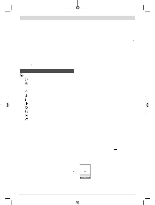
Continuous measurement
In continuous measurement mode, the measuring tool can be moved relative to the target, during which the measured value will be updated every half a second. You can, for ex-
1 609 92A 62J | (22.09.2020) |
|
|
|
Bosch Power Tools |
|
|
|
|
|
|
|
|
|
|
|
|
|
|
|
|
|
|
|
ample, move a desired distance away from a wall while reading off the current distance at all times.
Select the continuous measurement mode 


 .
.
To switch on the laser beam, briefly press the measuring button (2) [ ].
].
Move the measuring tool until the required distance value is shown in the display below.
Briefly pressing the measuring button (2) [ ] will interrupt the continuous measurement. The current measured value will be shown at the bottom of the display. The maximum and minimum measured value appear above it. Pressing the measuring button (2) [
 ] once
more will start the continuous measurement again. Continuous measurement automatically switches off after five minutes.
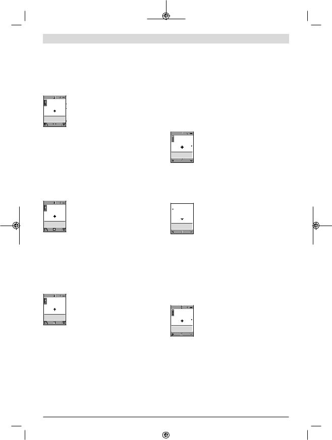
Area measurement
Select the area measurement mode  .
.
Then measure the width and length and height one after the other as with a length measurement. The laser beam remains switched on between the two measurements. The distance to be measured flashes in the indicator for area measurement  (see indicator element (j)).
The first measured value is shown at the top of
the display.
After the second measurement has been completed, the area will be automatically calcu-
lated and displayed. The end result is shown at the bottom of the display, while the individual
measured values are shown above it.
Volume measurement
Select the volume measurement mode  .
.
Then measure the width, length and depth one after the other as with a length measurement. The laser beam remains switched on between the three measurements. The distance to be measured flashes in the indicator for volume measurement  (see display element (j)).
The first measured value is shown at the top of
the display.
After the third measurement has been completed, the volume will be automatically calcu-
lated and displayed. The end result is shown at the bottom of the display, while the individual
measured values are shown above it.
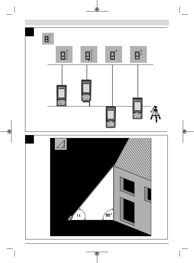
Indirect distance measurement
Select the indirect distance measurement mode  . There are four measuring functions available for the indirect distance measurement, each of which is capable of determining different distances.
The indirect distance measurement is used to determine distances that cannot be measured directly, due to an obstacle that would impede the path beam or the absence of a target surface that could serve as a reflector. This measuring procedure can only be employed vertically. Any horizontal deviation will lead to measurement errors.
English | 15
Note: Indirect distance measurement is always less accurate than direct distance measurement. For application-related reasons, measuring errors can be greater than with direct distance measurement. To improve the accuracy of measurement, we recommend the use of a tripod (accessory). The laser beam remains switched on between the individual measurements
a) Indirect height measurement (see figure B)
Select the indirect height measurement mode  .
.
Ensure that the measuring tool is at the same height as the lower measuring point. Then tilt the measuring tool around the reference level and measure distance 1 as for a length measurement (displayed as a red line).
Once the measurement is complete, the result
for the required distance X is displayed in the
result line (a). The measured values for distance 1 and angle α can be found in the meas-
ured value rows (h).
b) Double indirect height measurement (see figure C)
The measuring tool can indirectly measure all distances that lie in the vertical level of the measuring tool. Select the
double indirect height measurement mode  . Measure distances 1 and 2 in succession as for a length measurement.
  Once the measurement is complete, the result
  for the required distance X is displayed in the
  result row (a). The measured values for dis-
tances 1 and 2 and angle α can be found in the measured value rows (h).
Ensure that the reference level for the measurement (e.g. the rear edge of the measuring tool) remains in exactly the same place for all the individual measurements in a single measuring process.
c) Indirect length measurement (see figure D)
Select the indirect length measurement mode  .
.
Ensure that the measuring tool is at the same height as the required measuring point. Then tilt the measuring tool around the reference level and measure distance 1 as for a length measurement.
Once the measurement is complete, the result
for the required distance X is displayed in the
result row (a). The measured values for distance 1 and angle α can be found in the meas-
ured value row (h).
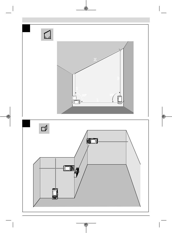
d) Trapezium measurement (see figure E)
The trapezium measurement can be used to determine the length of a roof slope, for example.
Select the trapezium measurement  .
.
Measure distances 1, 2 and 3 in succession as for a length measurement. Ensure that the measurement of distance 3 begins exactly at the point where distance 1 ends and that distances 2 and 3 are at right angles to distance 1.
Bosch Power Tools |
|
|
|
1 609 92A 62J | (22.09.2020) |
|
|
|
|
|
|
|
|
|
|
|
|
|
|
|
|
|
|
|
16 | English
13:20:23 |
|
Once the final measurement is complete, the |
09.06.2017 |
|
|
60º |
|
result for the required distance X is displayed |
|
3.624 M |
in the result line (a). The individual measured |
|
2.456 M |
|
|
4.872 M |
values can be found in the measured value |
|
4.356 M |
|
|
lines (h). |
|
|
|
|
|
|
|
Wall area measurement (see figure F)
The wall area measurement is used to determine the sum of multiple individual areas with a common height. In the illustrated example, the total area of several walls that have the same ceiling height H but different lengths L is to be determined.
Select the wall area measurement mode  .
.
Measure the ceiling height H as for a length measurement. The measured value is displayed in the top measured-value line. The laser remains switched on.
Then measure the length L1 of the first wall.
The area is automatically calculated and dis-
played in the result line (a). The last measured
value for length can be found in the bottom
measured value line.(h). The laser remains switched on.
Now measure the length L2 of the second wall. The individual measured value displayed in the measured value line (h) is added to the length L1. The sum of the two lengths (displayed in the middle measured value line (h)) is multiplied by the saved height H. The total area value is displayed in the result line (a).
You can measure any number of lengths Lx, which will be automatically added and multiplied by the height H. The requirement for a correct area calculation is that the first measured length (for example the ceiling height H) is identical for all sub-areas.
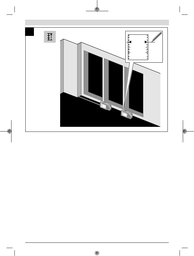
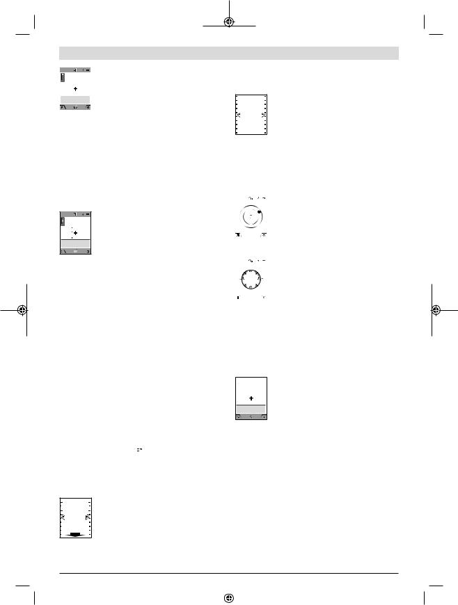
Stake out function (see figure G)
The stake out function repeatedly measures a defined length (distance). These lengths can be transferred to a surface, for example to enable material to be cut into pieces of equal lengths or to install stud walls in a drywall construction. The minimum adjustable length is 0.1 m and the maximum length is 50 m.
Note: The distance from the marking is shown in the display in the stake out function. The reference is not the edge of the measuring tool.
Select the stake out function  .
.
Use the button (4) [+] or the button (11) [–] to set the required length.
Begin the stake out function by pressing the measuring button (2) [ ] and slowly move away from the starting point.
 The measuring tool continuously measures the
 distance to the starting point. The defined
length and the current measured value are
thereby displayed. The lower or upper arrow
displays the shortest distance to the next or last marking.
Note: When measuring continuously, you can set a measured value as a defined length by pressing the measuring button (2) [ ].
].
The left factor specifies how many times the
defined length has already been reached. The
green arrows on either side of the display in-
dicate the reaching of a length for marking pur-
poses.
Red arrows or red text indicate the actual value when the reference is outside of the display.
Grade measurement/digital spirit level
Select the inclination measurement/digital spirit level 

 . The measuring tool automatically switches between two states.
|
The digital spirit level is used to check the hori- |
|
zontal or vertical alignment of an object (e.g. |
|
washing machine, refrigerator, etc.). |
|
When the inclination exceeds 3°, the ball in the |
|
display lights up red. |
|
The bottom of the measuring tool is used as |
|
|
the reference level for the digital spirit level. |
|
|
Grade measurement is used to measure a |
|
|
|
slope or incline (e.g. of stairs, railings, when |
88.0° |
fitting furniture, laying pipes, etc.). |
|
The left-hand side of the measuring tool serves |
|
as the reference level for grade measurement. |
|
If the display flashes during measurement, the |
|
|
measuring tool has been tipped too heavily to the side.
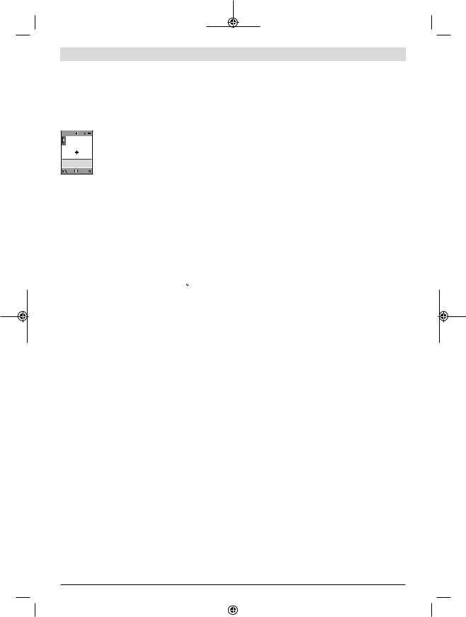
Memory functions
The value or end result of each completed measurement is automatically saved.
Memory value display
Maximum 50 values (measured values) can be retrieved. Select the memory function using the [ ] soft key (12).
  The number of the memory value is shown at
  the top of the display, the corresponding
memory value and the corresponding measur-
ing function are shown at the bottom.
Press the [+] button (4) to browse forwards through the saved values.
Press the [–] button (11) to browse backwards through the saved values.
If there is no value available in the memory, "0.000" is shown at the bottom of the display and "0" at the top.
The oldest value is located in position 1 in the memory, while the newest value is in position 50 (when 50 memory values are available). If a further value is saved, the oldest value in the memory is always deleted.
Deleting the memory
To open the memory, press the [ ] soft key (12). Press the [
 ] soft key (3) as often as required to delete the saved measurements in reverse order. To delete all the contents of the memory, press the [
 ] soft key (3) and the zoom button (5) at the same time.
1 609 92A 62J | (22.09.2020) |
|
|
|
Bosch Power Tools |
|
|
|
|
|
|
|
|
|
|
|
|
|
|
|
|
|
|
|
Adding/subtracting values
Measured values or end results can be added or subtracted.
Adding values
The following example describes the addition of areas: Determine an area as described in the section on area measurement (see "Area measurement", page 15).
Press the button (4) [+]. The calculated area
and the + symbol will be displayed. Press the measuring button (2) [ ] to start another area measurement. Measure the area as described
in the section on area measurement (see "Area
measurement", page 15). Once the second measurement is completed, the result of the second area measurement is displayed below. To show the end result, press the measuring button (2) [ ] once more.
Note: In the case of a length measurement, the end result is displayed immediately.
Subtracting values
To subtract values, press the button (11) [–]. The subsequent steps are the same as for the section on adding values.
Deleting measured values
Briefly pressing the on/off/delete button (9) [ ] will delete the last measured value in all measuring functions.
Bluetooth® interface
Transmitting data to other devices
The measuring tool is fitted with a Bluetooth® module which enables wireless data transfer to certain mobile devices with a Bluetooth® interface (e.g. smartphone, tablet).
Information about the system requirements for a Bluetooth® connection can be found on the Bosch website at www.bosch pt.com
uFurther information can be found on the Bosch product page.
When transmitting data by means of Bluetooth®, time lags may occur between the mobile device and the measuring tool. This can be due to the distance between the two devices or the measurement object itself.
Activating the Bluetooth® interface for transmitting data
to a mobile device
The Bluetooth® interface is activated in the settings. To activate the Bluetooth® signal, press the button (4) [+]. Ensure that the Bluetooth® interface is activated on your mobile device.
The Bosch Measuring Master app is specially designed to extend the range of functions of the mobile device and make data easier to process. This can be downloaded from the respective store of the device.
The connection between the mobile device and the measuring tool is established after the Bosch application has started. If multiple active measuring tools are found, select the appropriate measuring tool using the serial number. You can
English | 17
find the serial number (15) on your measuring tool's type plate.
The connection status, as well as the active connection (f), are shown in the display (1) of the measuring tool.
Deactivating the Bluetooth® interface
The Bluetooth® connection is deactivated in the settings. To deactivate the Bluetooth® signal, press the button (11) [–] or switch off the measuring tool.
Practical advice
uFurther information can be found on the Bosch product page.
uThe measuring tool is equipped with a wireless interface. Local operating restrictions, e.g. in aeroplanes or hospitals, must be observed.
General advice
The reception lens (18), the laser beam output (19) and the camera (20) must not be covered during measurement.
The measuring tool must not be moved while a measurement is being taken. For this reason, place the measuring tool against or on a firm surface whenever possible.
Influences on the measuring range
The measuring range depends on the lighting conditions and the reflective properties of the target surface. For better visibility of the laser beam in strong extraneous light, use the integrated camera (20), the laser viewing glasses (26) (accessory) and the laser target plate (25) (accessory) or shade the target area.
Influences on the measurement result
Due to physical effects, the possibility of inaccurate measurements when measuring various surfaces cannot be excluded. These include:
–Transparent surfaces (e.g. glass, water)
–Reflective surfaces (e.g. polished metal, glass)
–Porous surfaces (e.g. insulating materials)
–Structured surfaces (e.g. roughcast, natural stone).
If necessary, use the laser target plate (25) (accessory) on these surfaces.
Inaccurate measurements are also possible where the laser is pointed at target surfaces diagonally.
Layers of air at different temperatures and indirectly received reflections can also influence the measured value.
Checking accuracy and calibrating the grade
measurement (see figure H)
Regularly check the accuracy of the grade measurement. This is accomplished by means of a reverse measurement. To do this, lay the measuring tool on a table and measure the inclination. Turn the measuring tool by 180° and measure the inclination again. The difference between the displayed values must not exceed 0.3°.
Bosch Power Tools |
|
|
|
1 609 92A 62J | (22.09.2020) |
|
|
|
|
|
|
|
|
|
|
|
|
|
|
|
|
|
|
|
18 | English
In case of greater deviation, the measuring tool must be recalibrated. To do so, select 
 in the settings. Follow the directions on the display.
We recommend that you perform an accuracy check and if necessary a calibration of the measuring tool after extreme temperature variations and after impact to the tool. After a temperature variation, the measuring tool must acclimatise for a while before calibration is performed.
Accuracy check of the distance measurement
You can check the accuracy of the measuring tool as follows:
–Choose a measuring section of approx. 3 to 10 m in length that is permanently unchanged, the exact length of which is known to you (e.g. room width, door opening). The measurement should be performed under favourable conditions, i.e. the measuring section should be indoors with weak backlighting and the target area of the measurement should be smooth and reflect well (e.g. a whitepainted wall).
–Measure the section ten times in succession.
The deviation of the individual measurements from the mean value must not exceed ±2 mm over the entire measuring section in favourable conditions. Record the measurements in order to be able to compare the accuracy later on.
Checking accuracy and calibrating the target
indicator (crosshairs)
Check the accuracy of the alignment of the laser and target indicator on a regular basis.
–Select a bright area at least five metres away with as little illumination as possible (e.g. a white wall) as the target.
–Check whether the laser point is inside the target indicator in the display.
If the laser point is not inside the target indicator, you must recalibrate the target indicator.
To do so, select 
 in the settings. Follow the directions on the display.
For longer distances (of approx. more than five metres), a target marker is also superimposed to mark the measuring point.
Working with the tripod (accessory)
The use of a tripod is particularly necessary for larger distances. Place the measuring tool with the 1/4" thread (17) on the quick-release plate of the tripod (27) or a commercially available camera tripod. Tighten it using the locking screw of the quick-release plate.
Set the reference level for measurements with a tripod in the settings (tripod reference level).
Errors – Causes and Corrective
Measures
Cause |
Corrective measures |
Temperature warning flashes, measurement not possible
The measuring tool is outside |
Wait until the measuring tool |
the operating temperature of |
has reached operating tem- |
-10 °C to +45 °C (in the con- |
perature. |
tinuous measurement func- |
|
tion, up to +40 °C). |
|
Display shows "ERROR" |
|
Addition/subtraction of |
Only add/subtract measured |
measured values with differ- |
values with the same units of |
ent units of measurement. |
measurement. |
Angle between laser beam |
Increase the angle between |
and target is too acute. |
the laser beam and the tar- |
|
get. |
Target surface is too reflect- |
Use the laser target plate |
ive (e.g. mirror) or not re- |
(25). |
flective enough (e.g. black |
|
material), or ambient light is |
|
too bright. |
|
The laser beam output (19), |
Wipe the laser beam output |
reception lens (18) or cam- |
(19), reception lens (18) or |
era (20) are fogged up (e.g. |
camera (20) dry with a soft |
due to a rapid temperature |
cloth. |
change). |
|
Calculated value is larger |
Divide the calculation into in- |
than +1,999,999 or smaller |
termediate steps. |
than -999,999 m2/m3. |
|
Display shows "CAL" and "ERROR" |
|
The calibration of the grade |
Repeat the calibration ac- |
measurement has not been |
cording to the instructions |
carried out in the right order |
that appear on the display |
or has not been carried out in |
and in the manual. |
the correct positions. |
|
The surfaces used for calib- |
Repeat the calibration on a |
ration were not precisely ho- |
horizontal or vertical surface |
rizontal or vertical. |
and check the surfaces be- |
|
forehand if necessary using a |
|
spirit level. |
The measuring tool has |
Repeat the calibration and |
moved or tilted when the |
hold the measuring tool still |
button was pressed. |
against the surface when |
|
pressing the button. |
Measurement result implausible |
|
Target surface reflection not |
Cover the target surface. |
distinct (e.g. water, glass). |
|
The laser beam output (19), |
Keep the laser beam output |
reception lens (18) or cam- |
(19), reception lens (18) |
era (20) is covered. |
and camera (20) clear. |
1 609 92A 62J | (22.09.2020) |
|
|
|
Bosch Power Tools |
|
|
|
|
|
|
|
|
|
|
|
|
|
|
|
|
|
|
|
Cause |
Corrective measures |
An incorrect reference level |
Select a reference level that |
has been set. |
is appropriate for the meas- |
|
urement. |
Obstruction in the path of the The laser point must be fully
laser beam. |
on the target surface. |
Bluetooth® cannot be activated |
|
Batteries too weak. |
Change the batteries |
Switch Bluetooth® off and back on again on the measuring tool and mobile device.
Check the application on your mobile device.
Check whether Bluetooth® is activated on your measuring tool and mobile device.
Check whether your mobile device has been overloaded.
Reduce the distance between the measuring tool and your mobile device.
Where possible, ensure that there are no obstructions (e.g. reinforced concrete, metal doors) between the measuring tool and your mobile device. Keep the equipment away from any sources of electromagnetic interference (e.g. WiFi transmitters).
The measuring tool monitors for correct operation in every measurement. If a defect is detected, the display will indicate only the symbol shown opposite. In this case, or if you are unable to rectify an error using the corrective
measures above, send the measuring tool to Bosch customer service via your dealer.
| 19
outlet aperture or camera using pointed objects, and do not wipe over the reception lens, laser beam outlet aperture or camera (risk of scratching).
If the measuring tool needs to be repaired, send it off in the protective bag (23).
After-Sales Service and Application Service
Our after-sales service responds to your questions concerning maintenance and repair of your product as well as spare parts. You can find explosion drawings and information on spare parts at: www.bosch-pt.com
The Bosch product use advice team will be happy to help you with any questions about our products and their accessories.
In all correspondence and spare parts orders, please always include the 10 digit article number given on the nameplate of the product.
Malaysia
Robert Bosch Sdn. Bhd.(220975-V) PT/SMY
No. 8A, Jalan 13/6
46200 Petaling Jaya
Selangor
Tel.: (03) 79663194
Toll-Free: 1800 880188
Fax: (03) 79583838
E-Mail: kiathoe.chong@my.bosch.com
www.bosch-pt.com.my
You can find further service addresses at:
www.bosch-pt.com/serviceaddresses
Disposal
Measuring tools, accessories and packaging should be recycled in an environmentally friendly manner.
Do not dispose of measuring tools or batteries with household waste.
Only for AUS/NZ:
Supplier code ERAC000385
Maintenance and Service
Maintenance and Cleaning
Keep the measuring tool clean at all times.
Never immerse the measuring tool in water or other liquids. Wipe off any dirt using a damp, soft cloth. Do not use any detergents or solvents.
Clean the reception lens (18), laser beam outlet aperture
(19) and camera (20) particularly carefully: Ensure that there is no dirt on the reception lens, the laser beam outlet aperture or the camera. Only clean the reception lens, the laser beam outlet aperture and the camera with cleaning agents that are also suitable for camera lenses. Do not attempt to remove dirt from the reception lens, laser beam


Bosch Power Tools |
|
|
|
1 609 92A 62J | (22.09.2020) |
|
|
|
|
|
|
|
|
|
|
|
|
|
|
|
|
|
|
|
20 |
u(1)
u 請於第一次使用前將隨附的當地語言說明貼紙貼 覆於其上。
傷害。
u 立刻將頭轉離光束範圍。
u 光照射並沒有保護作用。
u 全性能。
u 具。
u 點燃粉塵或氣體。
Bluetooth® Bluetooth
SIG, Inc. Robert Bosch Power Tools GmbH
uBluetooth®
Bluetooth®Bluetooth®
測量結果可透過Bluetooth®
(2)[ ]
]
(3)[ ]
]
(4)[+]
(9)[ ]
]
(11)[−]
(12)[ ]
]
(13)[Func]
(17)1/4"
(25)A)
(26)A)
(27)A)
A) 中。本公司的配件清單中有完整的配件供應項目。
Bluetooth®
Bluetooth®
1 609 92A 62J | (22.09.2020) |
|
|
|
Bosch Power Tools |
|
|
|
|
|
|
|
|
|
|
|
|
|
|
|
|
|
|
|
|
GLM 150 C |
|
|
|
3 601 K72 F.. |
|
0.08–150 mA) |
|
0.08–60 mB) |
|
|
|
±1.5 mmA) |
|
±3.0 mmB) |
|
|
|
0.5 mm |
|
|
|
0°–360° (4x90°) |
|
|
|
0°–360° (4x90°) |
|
±0.2°C)D)E) |
|
0.1° |
|
|
|
–10 °C ...+45°CF) |
|
–20 °C ...+70 °C |
|
+5 °C...+40 °C |
|
90 % |
|
2000 m |
|
|
IEC 61010-1 |
2G) |
|
|
|
2 |
|
650 nm, < 1 mW |
25 °C |
|
– 10 m |
9 mm |
– 100 m |
90 mm |
|
|
– |
20 |
– |
5 H) |
|
|
|
3 x 1.5 V LR6 (AA) |
EPTA- |
0.23 kg |
Procedure 01:2014 |
|
|
142 (176) x 64 x 28 mm |
|
IP 54 |
|
|
|
|
Bluetooth® |
Bluetooth® |
|
4.2 I) |
|
2402 – 2480 MHz |
|
| 21 |
|
|
|
GLM 150 C |
|
|
|
8 mW |
A)25 °C± 0.05 mm/m
B)±
0.15 mm/m
C)0° 90° 45° ±0.01° H
D)25 °C
F)+40 °C
G) 暫時性導電
H)2 5 10
I)Bluetooth®
Bluetooth® GATT
(15)
–(7) (8) 180°
–(16) (21)
uTrackMyTools
u 產生眩光。
u 照射在儀器上。
u 才能繼續使用( ,
26)
Bosch Power Tools |
|
|
|
1 609 92A 62J | (22.09.2020) |
|
|
|
|
|
|
|
|
|
|
|
|
|
|
|
|
|
|
|
Loading...