


Robert Bosch GmbH
Power Tools Division
70745 Leinfelden-Echterdingen
Germany
www.bosch-pt.com
1 609 929 S02 (2009.03) T / 334 XXX
GLL 2-50 Professional
|
|
|
|
|
|
|
de |
Originalbetriebsanleitung |
cs |
Původní návod k používání |
cn |
|
|
en Original instructions |
sk Pôvodný návod na použitie |
tw |
|
|||
fr |
Notice originale |
hu Eredeti használati utasítás |
||||
ko |
|
|||||
es |
Manual original |
ru |
Оригинальное руководство |
|||
th |
|
|||||
pt |
Manual original |
|
по эксплуатации |
|||
it |
Istruzioni originali |
uk Оригінальна інструкція з |
id |
Petunjuk-Petunjuk untuk |
||
nl |
Oorspronkelijke gebruiks- |
|
експлуатації |
|
Penggunaan Orisinal |
|
|
aanwijzing |
ro |
Instrucţiuni originale |
vi |
BΩng hõëng dÿn nguy›n bΩn |
|
da Original brugsanvisning |
bg |
Оригинална инструкция |
ar |
ΔϴϠλϷ ϞϴϐθΘϟ ΕΎϤϴϠόΗ |
||
sv |
Bruksanvisning i original |
sr |
Originalno uputstvo za rad |
fa |
̶Ϡλ έΎ̯ ίήσ ̵ΎϤϨϫέ |
|
no |
Original driftsinstruks |
sl |
Izvirna navodila |
|
|
|
fi |
Alkuperäiset ohjeet |
hr |
Originalne upute za rad |
|
|
|
el |
Πρωτότυπο οδηγιών χρήσης |
et |
Algupärane kasutusjuhend |
|
|
|
tr |
Orijinal işletme talimat |
lv |
Instrukcijas oriģinālvalodā |
|
|
|
pl |
Instrukcja oryginalna |
lt |
Originali instrukcija |
|
|
|

2 |
Deutsch . . . . . . . . . . . . . . . . . . . . . . . . |
. . . . Seite |
6 |
English . . . . . . . . . . . . . . . . . . . . . . . . . . |
. . . Page |
16 |
Français . . . . . . . . . . . . . . . . . . . . . . . . . |
. . . Page |
27 |
Español. . . . . . . . . . . . . . . . . . . . . . . . . . |
. .Página |
37 |
Português . . . . . . . . . . . . . . . . . . . . . . . . |
. .Página |
47 |
Italiano . . . . . . . . . . . . . . . . . . . . . . . . . . |
. .Pagina |
57 |
Nederlands . . . . . . . . . . . . . . . . . . . . . . . |
. .Pagina |
67 |
Dansk . . . . . . . . . . . . . . . . . . . . . . . . . . . |
. . . Side |
76 |
Svenska . . . . . . . . . . . . . . . . . . . . . . . . . |
. . . Sida |
85 |
Norsk . . . . . . . . . . . . . . . . . . . . . . . . . . . |
. . . Side |
94 |
Suomi . . . . . . . . . . . . . . . . . . . . . . . . . . . |
. . . .Sivu |
103 |
Ελληνικά . . . . . . . . . . . . . . . . . . . . . . . . . |
. . Σελίδα |
112 |
Türkçe . . . . . . . . . . . . . . . . . . . . . . . . . . |
. . . Sayfa |
122 |
Polski . . . . . . . . . . . . . . . . . . . . . . . . . . . |
. .Strona |
131 |
Česky . . . . . . . . . . . . . . . . . . . . . . . . . . . |
. . Strana |
141 |
Slovensky . . . . . . . . . . . . . . . . . . . . . . . . |
. . Strana |
150 |
Magyar . . . . . . . . . . . . . . . . . . . . . . . . . . |
. . . Oldal |
159 |
Русский . . . . . . . . . . . . . . . . . . . . . . . . |
Страница |
169 |
Українська . . . . . . . . . . . . . . . . . . . . . . . |
Сторінка |
180 |
Română . . . . . . . . . . . . . . . . . . . . . . . . . |
. . Pagina |
190 |
Български . . . . . . . . . . . . . . . . . . . . . . |
Страница |
199 |
Srpski . . . . . . . . . . . . . . . . . . . . . . . . . . . |
. . Strana |
209 |
Slovensko . . . . . . . . . . . . . . . . . . . . . . . . |
. . . Stran |
218 |
Hrvatski . . . . . . . . . . . . . . . . . . . . . . . . . |
Stranica |
227 |
Eesti . . . . . . . . . . . . . . . . . . . . . . . . . . . . |
Lehekülg |
236 |
Latviešu . . . . . . . . . . . . . . . . . . . . . . . . . |
Lappuse |
245 |
Lietuviškai . . . . . . . . . . . . . . . . . . . . . . . |
Puslapis |
255 |
. . . . . . . . . . . . . . . . . . . . . . . . . . . . |
. . . . . 265 |
|
. . . . . . . . . . . . . . . . . . . . . . . . . . . . |
. . . . . 273 |
|
. . . . . . . . . . . . . . . . . . . . . . . . . . . |
. . . . . 281 |
|
. . . . . . . . . . . . . . . . . . . . . . . . . . |
. . . . |
289 |
Bahasa Indonesia . . . . . . . . . . . . . . . . . . |
Halaman |
298 |
Tiøng Vi·t . . . . . . . . . . . . . . . . . . . . . . . . |
. . .Trang |
308 |
. . . . . . . . . . . . . . . . . . . . . . . . . . . . |
. . . ΔΤϔλ |
317 |
vÝ—U . . . . . . . . . . . . . . . . . . . . . . . . . . |
. . . ϪΤϔλ |
325 |
1 609 929 S02 | (19.3.09) |
Bosch Power Tools |

3 | |
|
|
|
3 |
4 |
5 |
6 |
2 |
|
|
|
1 |
|
|
7 |
1 |
|
|
|
|
|
8 |
|
|
|
18 |
|
|
2 605 438 682 |
|
|
|
|
OPEN |
9 |
|
|
17 |
10 |
|
|
|
|
ional |
1 609 203 X77 |
|
|
Profess |
|
|
|
|
|
15 |
11 |
|
|
|
12 |
14 |
|
13 |
|
|
|
16 |
14 |
|
|
13 |
|
|
|
|
15 |
1 609 929 S02 | (19.3.09) |
|
|
Bosch Power Tools |
4 | |
|
A |
B |
C |
D |
E |
F |
1 609 929 S02 | (19.3.09) |
Bosch Power Tools |
5 | |
|
|
|
G |
H |
|
|
I |
J |
|
|
K |
L |
19 |
|
2 607 990 031 |
0 601 015 B00 |
||
|
|
0 601 015 A00 |
|
|
|
20 |
|
|
|
2 607 002 195 |
|
|
|
|
21 |
|
0 601 096 974 |
0 601 069 100 |
|
1 609 929 S02 | (19.3.09) |
|
|
Bosch Power Tools |
6 | Deutsch
Sicherheitshinweise
Sämtliche Anweisungen sind zu lesen, um mit dem Messwerkzeug gefahrlos und sicher zu arbeiten. Machen Sie Warnschilder am Messwerkzeug niemals unkenntlich. BEWAHREN SIE DIESE ANWEISUNGEN GUT AUF.
fVorsicht – wenn andere als die hier angegebenen Bedienungsoder Justiereinrichtungen benutzt oder andere Verfahrensweisen ausgeführt werden, kann dies zu gefährlicher Strahlungsexposition führen.
fDas Messwerkzeug wird mit einem Warnschild in englischer Sprache ausgeliefert (in der Darstellung des Messwerkzeugs auf der Grafikseite mit Nummer 10 gekennzeichnet).
fVerwenden Sie die Laser-Sichtbrille nicht als Schutzbrille. Die Laser-Sichtbrille dient zum besseren Erkennen des Laserstrahls, sie schützt jedoch nicht vor der Laserstrahlung.
fVerwenden Sie die Laser-Sichtbrille nicht als Sonnenbrille oder im Straßenverkehr.
Die Laser-Sichtbrille bietet keinen vollständigen UV-Schutz und vermindert die Farbwahrnehmung.
fLassen Sie das Messwerkzeug von qualifiziertem Fachpersonal und nur mit OriginalErsatzteilen reparieren. Damit wird sichergestellt, dass die Sicherheit des Messwerkzeuges erhalten bleibt.
fLassen Sie Kinder das Laser-Messwerkzeug nicht unbeaufsichtigt benutzen. Sie könnten unbeabsichtigt Personen blenden.
fArbeiten Sie mit dem Messwerkzeug nicht in explosionsgefährdeter Umgebung, in der sich brennbare Flüssigkeiten, Gase oder Stäube befinden. Im Messwerkzeug können Funken erzeugt werden, die den Staub oder die Dämpfe entzünden.
fÜberkleben Sie das englische Warnschild vor der ersten Inbetriebnahme mit dem mitgelieferten Aufkleber in Ihrer Landessprache.
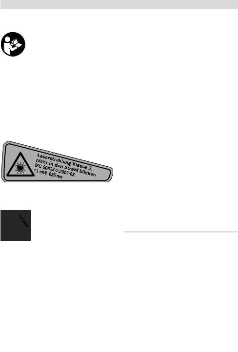
Richten Sie den Laserstrahl nicht auf Personen oder Tiere und blicken Sie nicht selbst in den Laserstrahl. Dieses Messwerkzeug erzeugt Laserstrahlung der Laserklasse 2 gemäß IEC 60825-1. Dadurch können Sie Personen blenden.
Funktionsbeschreibung
Bitte klappen Sie die Ausklappseite mit der Darstellung des Messwerkzeugs auf, und lassen Sie diese Seite aufgeklappt, während Sie die Betriebsanleitung lesen.
Bestimmungsgemäßer Gebrauch
Das Messwerkzeug ist bestimmt zum Ermitteln und Überprüfen von waagrechten und senkrechten Linien.
1 609 929 S02 | (19.3.09) |
Bosch Power Tools |

|
Deutsch | 7 |
|
|
Technische Daten |
|
|
|
Kreuzlinienlaser |
GLL 2-50 |
|
Professional |
Sachnummer |
3 601 K63 1.. |
Arbeitsbereich |
|
– Standard |
20 m |
– mit Pulsfunktion |
15 m |
– mit Laserempfänger |
50 m |
Nivelliergenauigkeit |
±0,3 mm/m |
Selbstnivellierbereich typisch |
±4° |
Nivellierzeit typisch |
<4 s |
Betriebstemperatur |
–10 °C ... +50 °C |
Lagertemperatur |
–20 °C ... +70 °C |
Relative Luftfeuchte max. |
90 % |
Laserklasse |
2 |
Lasertyp |
635 nm, <1 mW |
C6 |
1 |
kürzeste Impulsdauer |
1/1600 s |
Stativaufnahme |
1/4" |
Batterien |
3 x 1,5 V LR6 (AA) |
Betriebsdauer ca. |
12 h |
Abschaltautomatik nach ca. |
30 min |
Gewicht entsprechend EPTA-Procedure 01/2003 |
0,45 kg |
Maße |
118 x 57 x 89 mm |
Schutzart |
IP 54 (staubund spritzwassergeschützt) |
|
|
Bitte beachten Sie die Sachnummer auf dem Typenschild Ihres Messwerkzeugs, die Handelsbezeichnungen einzelner Messwerkzeuge können variieren.
Zur eindeutigen Identifizierung Ihres Messwerkzeugs dient die Seriennummer 9 auf dem Typenschild.
Bosch Power Tools |
1 609 929 S02 | (19.3.09) |

8 | Deutsch
Abgebildete Komponenten
Die Nummerierung der abgebildeten Komponenten bezieht sich auf die Darstellung des Messwerkzeugs auf der Grafikseite.
1Austrittsöffnung Laserstrahlung
2Anzeige Pulsfunktion
3Taste Pulsfunktion
4Betriebsarten-Taste
5Batterie-Anzeige
6Stativaufnahme 1/4"
7Ein-/Ausschalter
8Batteriefachdeckel
9Seriennummer
10Laser-Warnschild
11Arretierung des Batteriefachdeckels
12Ausrichtscheibe*
13Ausrichthilfe 0° an der Ausrichtscheibe
14Ausrichthilfe 90° an der Ausrichtscheibe
15Ausrichthilfe 45° an der Ausrichtscheibe
16Stift an der Ausrichtscheibe
17Schutztasche*
18Koffer*
19Laser-Sichtbrille*
20Messplatte mit Fuß*
21Laserempfänger*
*Abgebildetes oder beschriebenes Zubehör gehört nicht zum Standard-Lieferumfang.
Montage
Batterien einsetzen/wechseln
Verwenden Sie ausschließlich Alkali-Mangan- Batterien.
Zum Öffnen des Batteriefachdeckels 8 drücken Sie die Arretierung 11 in Pfeilrichtung und nehmen den Batteriefachdeckel ab. Setzen Sie die mitgelieferten Batterien ein. Achten Sie dabei auf die richtige Polung entsprechend der Darstellung auf der Innenseite des Batteriefachs.
Blinkt die Batterie-Anzeige 5 rot, dann müssen Sie die Batterien wechseln.
Ersetzen Sie immer alle Batterien gleichzeitig. Verwenden Sie nur Batterien eines Herstellers und mit gleicher Kapazität.
fNehmen Sie die Batterien aus dem Messwerkzeug, wenn Sie es längere Zeit nicht benutzen. Die Batterien können bei längerer Lagerung korrodieren und sich selbst entladen.
Betrieb
Inbetriebnahme
fSchützen Sie das Messwerkzeug vor Nässe und direkter Sonneneinstrahlung.
fSetzen Sie das Messwerkzeug keinen extremen Temperaturen oder Temperaturschwankungen aus. Lassen Sie es z.B. nicht längere Zeit im Auto liegen. Lassen Sie das Messwerkzeug bei größeren Temperaturschwankungen erst austemperieren, bevor Sie es in Betrieb nehmen. Bei extremen Temperaturen oder Temperaturschwankungen kann die Präzision des Messwerkzeugs beeinträchtigt werden.
fVermeiden Sie heftige Stöße oder Stürze des Messwerkzeuges. Nach starken äußeren Einwirkungen auf das Messwerkzeug sollten Sie vor dem Weiterarbeiten immer eine Genauigkeitsüberprüfung durchführen (siehe „Nivelliergenauigkeit“).
fSchalten Sie das Messwerkzeug aus, wenn Sie es transportieren. Beim Ausschalten wird die Pendeleinheit verriegelt, die sonst bei starken Bewegungen beschädigt werden kann.
1 609 929 S02 | (19.3.09) |
Bosch Power Tools |

Ein-/Ausschalten
Zum Einschalten des Messwerkzeugs schieben Sie den Ein-/Ausschalter 7 in die Position
„ on“ (für Arbeiten ohne Nivellierautomatik) oder in die Position „
 on“ (für Arbeiten mit Nivellierautomatik). Das Messwerkzeug sendet sofort nach dem Einschalten Laserlinien aus den Austrittsöffnungen 1.
fRichten Sie den Laserstrahl nicht auf Personen oder Tiere und blicken Sie nicht selbst in den Laserstrahl, auch nicht aus größerer Entfernung.
Zum Ausschalten des Messwerkzeugs schieben Sie den Ein-/Ausschalter 7 in die Position „off“. Beim Ausschalten wird die Pendeleinheit verriegelt.
Abschaltautomatik deaktivieren
Das Messwerkzeug schaltet sich nach 30 min Betriebsdauer automatisch ab. Um die Abschaltautomatik zu deaktivieren, halten Sie beim Einschalten des Messwerkzeugs die BetriebsartenTaste 4 3 s lang gedrückt. Ist die Abschaltautomatik deaktiviert, blinken die Laserlinien nach 3 s kurz.
fLassen Sie das eingeschaltete Messwerkzeug nicht unbeaufsichtigt und schalten Sie das Messwerkzeug nach Gebrauch ab.
Andere Personen könnten vom Laserstrahl geblendet werden.
Um die automatische Abschaltung zu aktivieren, schalten Sie das Messwerkzeug aus und wieder ein (ohne gedrückte Betriebsarten-Taste 4).
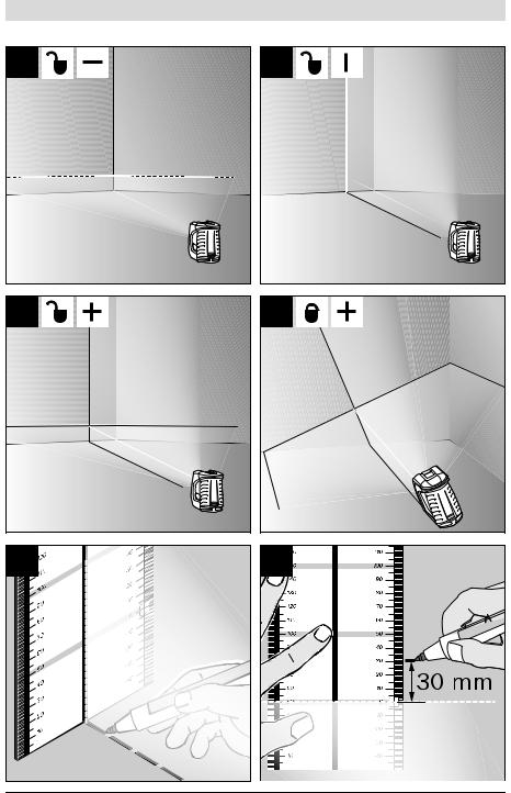
Betriebsarten (siehe Bilder A–D)
Das Messwerkzeug verfügt über drei Betriebsarten, zwischen denen Sie jederzeit wechseln können:
–Horizontalbetrieb „–“: erzeugt eine waagrechte Laserlinie,
–Vertikalbetrieb „l“: erzeugt eine senkrechte Laserlinie,
–Kreuzlinienbetrieb „+“: erzeugt eine waagrechte und eine senkrechte Laserlinie.
Deutsch | 9
Nach dem Einschalten befindet sich das Messwerkzeug im Kreuzlinienbetrieb. Um die Betriebsart zu wechseln, drücken Sie die Betriebs- arten-Taste 4.
Alle drei Betriebsarten können sowohl mit als auch ohne Nivellierautomatik gewählt werden.
Pulsfunktion
Für das Arbeiten mit dem Laserempfänger 21 muss – unabhängig von der gewählten Betriebsart – die Pulsfunktion aktiviert werden.
In der Pulsfunktion blinken die Laserlinien mit sehr hoher Frequenz und werden dadurch für den Laserempfänger 21 auffindbar.
Zum Einschalten der Pulsfunktion drücken Sie die Taste 3. Bei eingeschalteter Pulsfunktion leuchtet die Anzeige 2 grün.
Für das menschliche Auge ist die Sichtbarkeit der Laserlinien bei eingeschalteter Pulsfunktion verringert. Für Arbeiten ohne Laserempfänger schalten Sie deshalb die Pulsfunktion durch erneutes Drücken der Taste 3 aus. Bei ausgeschalteter Pulsfunktion erlischt die Anzeige 2.
Nivellierautomatik
Arbeiten mit Nivellierautomatik (siehe Bild C)
Stellen Sie das Messwerkzeug auf eine waagrechte, feste Unterlage oder befestigen Sie es auf einem handelsüblichen Fotostativ.
Schieben Sie für Arbeiten mit Nivellierautomatik den Ein-/Ausschalter 7 in Position „ on“.
on“.
Die Nivellierautomatik gleicht Unebenheiten innerhalb des Selbstnivellierbereiches von ±4° automatisch aus. Sobald die Laserlinien nicht mehr blinken, ist das Messwerkzeug einnivelliert.
Ist die automatische Nivellierung nicht möglich, z.B. weil die Standfläche des Messwerkzeugs mehr als 4° von der Waagrechten abweicht, blinken die Laserlinien. Stellen Sie in diesem Fall das Messwerkzeug waagrecht auf und warten Sie die Selbstnivellierung ab.
Bei Erschütterungen oder Lageänderungen während des Betriebs wird das Messwerkzeug automatisch wieder einnivelliert. Überprüfen Sie nach einer erneuten Nivellierung die Position der waagrechten bzw. senkrechten Laserlinie in Bezug auf Referenzpunkte, um Fehler zu vermeiden.
Bosch Power Tools |
1 609 929 S02 | (19.3.09) |
10 | Deutsch
Arbeiten ohne Nivellierautomatik (siehe Bild D)
Schieben Sie für Arbeiten ohne Nivellierautomatik den Ein-/Ausschalter 7 in Position „ on“. Bei ausgeschalteter Nivellierautomatik blinken die Laserlinien dauerhaft.
Bei abgeschalteter Nivellierautomatik können Sie das Messwerkzeug frei in der Hand halten oder auf eine geneigte Unterlage stellen. Im Kreuzlinienbetrieb verlaufen die zwei Laserlinien nicht mehr zwingend senkrecht zueinander.
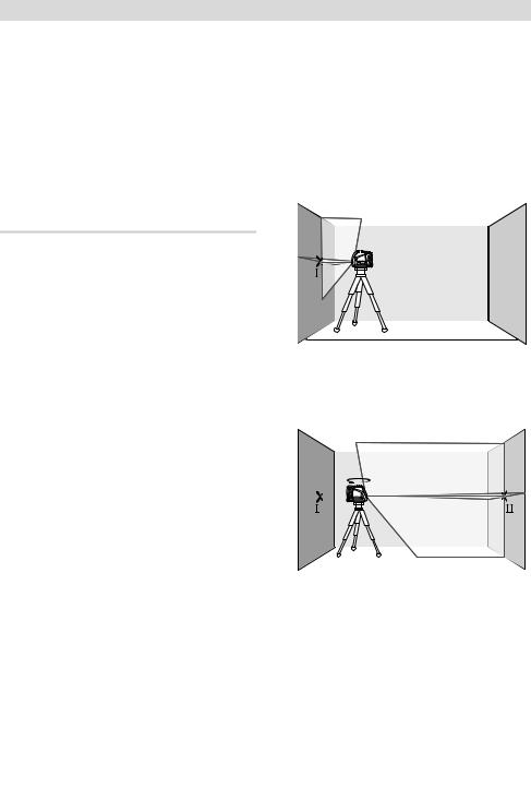
Höhengenauigkeit der waagrechten Linie überprüfen
Für die Überprüfung benötigen Sie eine freie Messstrecke von 5 m auf festem Grund zwischen zwei Wänden A und B.
–Montieren Sie das Messwerkzeug nahe der Wand A auf einem Stativ oder stellen Sie es auf festen, ebenen Untergrund. Schalten Sie das Messwerkzeug ein. Wählen Sie Kreuzlinienbetrieb mit Nivellierautomatik.
Nivelliergenauigkeit
Genauigkeitseinflüsse
Den größten Einfluss übt die Umgebungstemperatur aus. Besonders vom Boden nach oben verlaufende Temperaturunterschiede können den Laserstrahl ablenken.
Da die Temperaturschichtung in Bodennähe am größten ist, sollten Sie das Messwerkzeug ab einer Messstrecke von 20 m immer auf einem Stativ montieren. Stellen Sie das Messwerkzeug außerdem nach Möglichkeit in der Mitte der Arbeitsfläche auf.
Neben äußeren Einflüssen können auch gerätespezifische Einflüsse (wie z.B. Stürze oder heftige Stöße) zu Abweichungen führen. Überprüfen Sie deshalb vor jedem Arbeitsbeginn die Genauigkeit des Messwerkzeugs.
Überprüfen Sie jeweils zuerst die Höhensowie die Nivelliergenauigkeit der waagrechten Laserlinie, danach die Nivelliergenauigkeit der senkrechten Laserlinie.
Sollte das Messwerkzeug bei einer der Prüfungen die maximale Abweichung überschreiten, dann lassen Sie es von einem Bosch-Kunden- dienst reparieren.
A B
5 m
–Richten Sie den Laser auf die nahe Wand A und lassen Sie das Messwerkzeug einnivellieren. Markieren Sie die Mitte des Punktes, an dem sich die Laserlinien an der Wand kreuzen (Punkt I).
A B 180˚
–Drehen Sie das Messwerkzeug um 180°, lassen Sie es einnivellieren und markieren Sie den Kreuzungspunkt der Laserlinien an der gegenüberliegenden Wand B (Punkt II).
1 609 929 S02 | (19.3.09) |
Bosch Power Tools |
–Platzieren Sie das Messwerkzeug – ohne es zu drehen – nahe der Wand B, schalten Sie es ein und lassen Sie es einnivellieren.
A B
–Richten Sie das Messwerkzeug in der Höhe so aus (mit Hilfe des Stativs oder gegebenenfalls durch Unterlegen), dass der Kreuzungspunkt der Laserlinien genau den zuvor markierten Punkt II auf der Wand B trifft.
A |
180˚ B |
d
Deutsch | 11
Nivelliergenauigkeit der waagrechten Linie überprüfen
Für die Überprüfung benötigen Sie eine freie Fläche von ca. 5 x 5 m.
–Stellen Sie das Messwerkzeug auf festem, ebenem Grund in der Mitte zwischen den Wänden A und B auf. Lassen Sie das Messwerkzeug im Horizontalbetrieb einnivellieren.
A
|
5 |
|
|
|
|
|
m |
|
|
m |
|
|
|
|
|
|
|
|
|
2,5 |
|
|
B |
|
|
|
|
||
–Markieren Sie in 2,5 m Entfernung vom Messwerkzeug an beiden Wänden die Mitte der Laserlinie (Punkt I auf Wand A und Punkt II auf Wand B).
–Drehen Sie das Messwerkzeug um 180°, ohne die Höhe zu verändern. Richten Sie es so auf die Wand A, dass die senkrechte Laserlinie durch den bereits markierten Punkt I läuft. Lassen Sie das Messwerkzeug einnivellieren und markieren Sie den Kreuzungspunkt der Laserlinien auf der Wand A (Punkt III).
–Die Differenz d der beiden markierten Punkte I und III auf der Wand A ergibt die tatsächliche Höhenabweichung des Messwerkzeugs.
Die maximale zulässige Abweichung dmax berechnen Sie wie folgt:
dmax = doppelter Abstand der Wände x 0,3 mm/m Beispiel: Bei einem Abstand der Wände von 5 m darf die maximale Abweichung
dmax = 2 x 5 m x 0,3 mm/m = 3 mm betragen. Die Markierungen dürfen folglich höchstens
3 mm auseinander liegen.
A
,5m
B
–Stellen Sie das Messwerkzeug um 180° gedreht in 5 m Entfernung auf und lassen Sie es einnivellieren.
–Richten Sie das Messwerkzeug in der Höhe so aus (mit Hilfe des Stativs oder gegebenenfalls durch Unterlegen), dass die Mitte der Laserlinie genau den zuvor markierten Punkt II auf der Wand B trifft.
Bosch Power Tools |
1 609 929 S02 | (19.3.09) |
12 | Deutsch
–Markieren Sie auf der Wand A die Mitte der Laserlinie als Punkt III (senkrecht über bzw. unter dem Punkt I).
–Die Differenz d der beiden markierten Punkte I und III auf der Wand A ergibt die tatsächliche Abweichung des Messwerkzeugs von der Waagrechten.
Die maximale zulässige Abweichung dmax berechnen Sie wie folgt:
dmax = doppelter Abstand der Wände x 0,3 mm/m Beispiel: Bei einem Abstand der Wände von 5 m darf die maximale Abweichung
dmax = 2 x 5 m x 0,3 mm/m = 3 mm betragen. Die Markierungen dürfen folglich höchstens 3 mm
auseinander liegen.
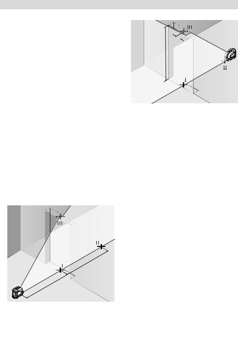
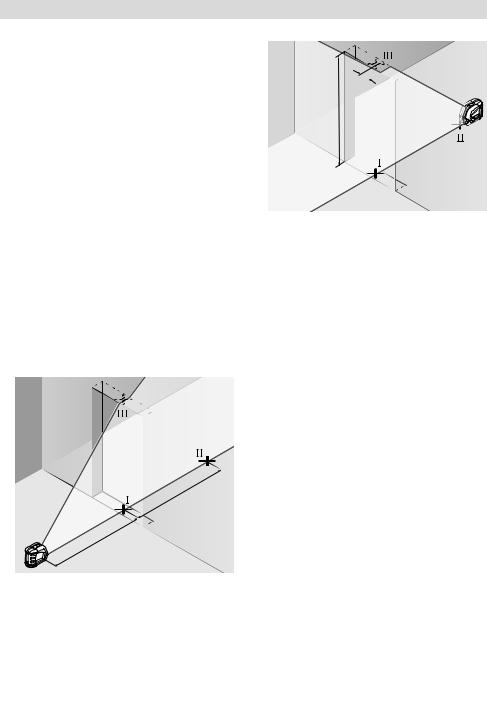
Nivelliergenauigkeit der senkrechten Linie überprüfen
Für die Überprüfung benötigen Sie eine Türöffnung, bei der (auf festem Grund) auf jeder Seite der Tür mindestens 2,5 m Platz sind.
–Stellen Sie das Messwerkzeug in 2,5 m Entfernung von der Türöffnung auf festem, ebenem Grund auf (nicht auf einem Stativ). Lassen Sie das Messwerkzeug im Kreuzlinienbetrieb einnivellieren, und richten Sie die Laserlinien auf die Türöffnung.
d
<![endif]>m2
–Stellen Sie das Messwerkzeug auf der anderen Seite der Türöffnung direkt hinter den Punkt II. Lassen Sie das Messwerkzeug einnivellieren und richten Sie die senkrechte Laserlinie so aus, dass ihre Mitte genau durch die Punkte I und II verläuft.
–Die Differenz d zwischen dem Punkt III
und der Mitte der Laserlinie am oberen Rand der Türöffnung ergibt die tatsächliche Abweichung des Messwerkzeugs von der Senkrechten.
–Messen Sie die Höhe der Türöffnung.
Die maximale zulässige Abweichung dmax berechnen Sie wie folgt:
dmax = doppelte Höhe der Türöffnung x 0,3 mm/m Beispiel: Bei einer Höhe der Türöffnung von 2 m darf die maximale Abweichung
dmax = 2 x 2 m x 0,3 mm/m = 1,2 mm betragen. Die Markierungen dürfen folglich höchstens
1,2 mm auseinander liegen.
m 2,5
–Markieren Sie die Mitte der senkrechten Laserlinie am Boden der Türöffnung (Punkt I), in 5 m Entfernung auf der anderen Seite der Türöffnung (Punkt II) sowie am oberen Rand der Türöffnung (Punkt III).
1 609 929 S02 | (19.3.09) |
Bosch Power Tools |

Arbeitshinweise
fVerwenden Sie immer nur die Mitte der Laserlinie zum Markieren. Die Breite der Laserlinie ändert sich mit der Entfernung.
Arbeiten mit der Ausrichtscheibe
Mit Hilfe der Ausrichtscheibe 12 können Sie das Messwerkzeug an einer Referenzlinie ausrichten oder die senkrechte Laserlinie im Winkel von 45° oder 90° zu einer Referenzlinie anzeigen.
Setzen Sie das Messwerkzeug mit der Stativaufnahme 6 auf den Stift 16 an der Ausrichtscheibe. Platzieren Sie es so auf der Ausrichtscheibe, dass die senkrechte Laserlinie (je nach gewünschtem Winkel) mittig durch die Ausrichthilfe 13, 14 oder 15 verläuft.
Richten Sie die Ausrichtscheibe 12 mit Hilfe der korrespondierenden Ausrichthilfen 13, 14 oder 15 auf die gewünschte Referenzlinie aus.
Arbeiten mit der Messplatte (Zubehör) (siehe Bilder E–F)
Mit Hilfe der Messplatte 20 können Sie die Lasermarkierung auf den Boden bzw. die Laserhöhe auf eine Wand übertragen.
Mit dem Nullfeld und der Skala können Sie den Versatz zur gewünschten Höhe messen und an anderer Stelle wieder antragen. Damit entfällt das exakte Einstellen des Messwerkzeugs auf die zu übertragende Höhe.
Die Messplatte 20 hat eine Reflexbeschichtung, die die Sichtbarkeit des Laserstrahls in größerer Entfernung bzw. bei starker Sonnenstrahlung verbessert. Die Helligkeitsverstärkung ist nur zu erkennen, wenn Sie parallel zum Laserstrahl auf die Messplatte blicken.
Deutsch | 13
Arbeiten mit dem Stativ (Zubehör)
Ein Stativ bietet eine stabile, höheneinstellbare Messunterlage. Setzen Sie das Messwerkzeug mit der Stativaufnahme 6 auf das 1/4"-Gewinde des Stativs auf und schrauben Sie es mit der Feststellschraube des Stativs fest.
Arbeiten mit Laserempfänger (Zubehör) (siehe Bild G)
Bei ungünstigen Lichtverhältnissen (helle Umgebung, direkte Sonneneinstrahlung) und auf größere Entfernungen verwenden Sie zum besseren Auffinden der Laserlinien den Laserempfänger 21. Schalten Sie beim Arbeiten mit dem Laserempfänger die Pulsfunktion ein (siehe „Pulsfunktion“, Seite 9).
Laser-Sichtbrille (Zubehör)
Die Laser-Sichtbrille filtert das Umgebungslicht aus. Dadurch erscheint das rote Licht des Lasers für das Auge heller.
fVerwenden Sie die Laser-Sichtbrille nicht als Schutzbrille. Die Laser-Sichtbrille dient zum besseren Erkennen des Laserstrahls, sie schützt jedoch nicht vor der Laserstrahlung.
fVerwenden Sie die Laser-Sichtbrille nicht als Sonnenbrille oder im Straßenverkehr.
Die Laser-Sichtbrille bietet keinen vollständigen UV-Schutz und vermindert die Farbwahrnehmung.
Bosch Power Tools |
1 609 929 S02 | (19.3.09) |

14 | Deutsch
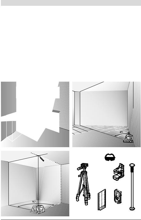
Arbeitsbeispiele (siehe Bilder H–K)
Bodenplatten im 45°-Winkel verlegen (siehe Bild J)
Setzen Sie das Messwerkzeug mit der Stativaufnahme 6 auf den Stift 16 an der Ausrichtscheibe. Platzieren Sie es so auf der mittleren Erhebung der Ausrichtscheibe 12, dass die senkrechte Laserlinie mittig durch die Ausrichthilfe 15 verläuft. Richten Sie dann die Ausrichtscheibe mit den Ausrichthilfen 13 oder 14 an der Referenzlinie aus.
Bei Kreuzlinienoder Vertikalbetrieb zeigt die senkrechte Laserlinie am Boden den 45°-Winkel zur Referenzlinie an. Richten Sie die Bodenplatten an dieser Linie aus.
Bodenpunkt (Lot) an Decke übertragen (siehe Bild K)
Zeichnen Sie zwei im rechten Winkel gekreuzte Linien durch den Punkt, den Sie an die Decke übertragen wollen. Setzen Sie die Ausrichtscheibe 12 auf das Linienkreuz und richten Sie sie mit den Ausrichthilfen 13 sowie 14 auf dem Linienkreuz aus.
Setzen Sie das Messwerkzeug mit der Stativaufnahme 6 auf den Stift 16 an der Ausrichtscheibe. Platzieren Sie es so auf einer der beiden äußeren Erhebungen auf der Ausrichtscheibe, dass die senkrechte Laserlinie mittig durch die entsprechende Ausrichthilfe 13 oder 14 verläuft. Wählen Sie Vertikalbetrieb und zeichnen Sie die Mitte der Linie, die über dem Messwerkzeug verläuft, an der Decke an.
Drehen Sie das Messwerkzeug auf der Ausrichtscheibe um 90°. Achten Sie darauf, dass Sie die Ausrichtscheibe dabei nicht verschieben. Zeichnen Sie nach dem Einnivellieren den Kreuzungspunkt der senkrechten Laserlinie mit der bereits angezeichneten Linie an. Der Kreuzungspunkt der beiden Linien ist der übertragene Lotpunkt.
Wartung und Service
Wartung und Reinigung
Lagern und transportieren Sie das Messwerkzeug nur in der Schutztasche 17 bzw. dem Koffer 18.
Halten Sie das Messwerkzeug stets sauber.
Tauchen Sie das Messwerkzeug nicht ins Wasser oder andere Flüssigkeiten.
Wischen Sie Verschmutzungen mit einem feuchten, weichen Tuch ab. Verwenden Sie keine Reinigungsoder Lösemittel.
Reinigen Sie insbesondere die Flächen an der Austrittsöffnung des Lasers regelmäßig und achten Sie dabei auf Fusseln.
Sollte das Messwerkzeug trotz sorgfältiger Herstellungsund Prüfverfahren einmal ausfallen, ist die Reparatur von einer autorisierten Kundendienststelle für Bosch-Elektrowerkzeuge ausführen zu lassen. Öffnen Sie das Messwerkzeug nicht selbst.
Geben Sie bei allen Rückfragen und Ersatzteilbestellungen bitte unbedingt die 10-stellige Sachnummer laut Typenschild des Messwerkzeugs an.
Senden Sie im Reparaturfall das Messwerkzeug in der Schutztasche 17 bzw. dem Koffer 18 ein.
Zubehör
Schutztasche 17 . . . . . . . . . . . . 1 609 203 X77 Koffer 18 . . . . . . . . . . . . . . . . . . 2 605 438 682 Laser-Sichtbrille 19 . . . . . . . . . . 2 607 990 031 Messplatte mit Fuß 20 . . . . . . . . 2 607 002 195 Laserempfänger 21 . . . . . . . . . . 0 601 069 100 Baustativ BS 150 . . . . . . . . . . . . 0 601 096 974 Universelle Halterung BM 1 . . . . 0 601 015 A00 Teleskopstange BT 350 . . . . . . . 0 601 015 B00
1 609 929 S02 | (19.3.09) |
Bosch Power Tools |

Kundendienst und Kundenberatung
Der Kundendienst beantwortet Ihre Fragen zu Reparatur und Wartung Ihres Produkts sowie zu Ersatzteilen. Explosionszeichnungen und Informationen zu Ersatzteilen finden Sie auch unter: www.bosch-pt.com
Das Bosch-Kundenberater-Team hilft Ihnen gerne bei Fragen zu Kauf, Anwendung und Einstellung von Produkten und Zubehören.
www.powertool-portal.de, das Internetportal für Handwerker und Heimwerker. www.ewbc.de, der Informations-Pool für Handwerk und Ausbildung.
Deutschland
Robert Bosch GmbH Servicezentrum Elektrowerkzeuge Zur Luhne 2
37589 Kalefeld – Willershausen
Tel. Kundendienst: +49 (1805) 70 74 10 Fax: +49 (1805) 70 74 11
E-Mail: Servicezentrum.Elektrowerkzeuge@de.bosch.com Tel. Kundenberatung: +49 (1803) 33 57 99
Fax: +49 (711) 7 58 19 30
E-Mail: kundenberatung.ew@de.bosch.com
Österreich
Tel.: +43 (01) 7 97 22 20 10
Fax: +43 (01) 7 97 22 20 11
E-Mail: service.elektrowerkzeuge@at.bosch.com
Schweiz
Tel.: +41 (044) 8 47 15 11
Fax: +41 (044) 8 47 15 51
Luxemburg
Tel.: +32 (070) 22 55 65
Fax: +32 (070) 22 55 75
E-Mail: outillage.gereedschap@be.bosch.com
Deutsch | 15
Entsorgung
Messwerkzeuge, Zubehör und Verpackungen sollen einer umweltgerechten Wiederverwertung zugeführt werden.
Nur für EU-Länder:
Werfen Sie Messwerkzeuge nicht in den Hausmüll!
Gemäß der Europäischen Richtlinie 2002/96/EG über Elektro-
und Elektronik-Altgeräte und ihrer Umsetzung in nationales Recht
müssen nicht mehr gebrauchsfähige Messwerkzeuge getrennt gesammelt und einer umweltgerechten Wiederverwertung zugeführt werden.
Akkus/Batterien:
Werfen Sie Akkus/Batterien nicht in den Hausmüll, ins Feuer oder ins Wasser. Akkus/Batterien sollen gesammelt, recycelt oder auf umweltfreundliche Weise entsorgt werden.
Nur für EU-Länder:
Gemäß der Richtlinie 91/157/EWG müssen defekte oder verbrauchte Akkus/Batterien recycelt werden.
Nicht mehr gebrauchsfähige Akkus/Batterien können direkt abgegeben werden bei:
Deutschland
Recyclingzentrum Elektrowerkzeuge Osteroder Landstraße 3
37589 Kalefeld
Schweiz
Batrec AG
3752 Wimmis BE
Änderungen vorbehalten.
Bosch Power Tools |
1 609 929 S02 | (19.3.09) |
16 | English
Safety Notes
Working safely with the measuring tool is possible only when the oper-
ating and safety information are
read completely and the instructions contained therein are strictly
followed. Never make warning labels on the measuring tool unrecognisable. SAVE THESE INSTRUCTIONS.
fCaution – The use of other operating or adjusting equipment or the application of other processing methods than those mentioned here, can lead to dangerous radiation exposure.
fThe measuring tool is provided with a warning label in English (marked with number 10 in the representation of the measuring tool on the graphics page).
fDo not use the laser viewing glasses as safety goggles. The laser viewing glasses are used for improved visualisation of the laser beam, but they do not protect against laser radiation.
fDo not use the laser viewing glasses as sun glasses or in traffic. The laser viewing glasses do not afford complete UV protection and reduce colour perception.
fHave the measuring tool repaired only through qualified specialists using original spare parts. This ensures that the safety of the measuring tool is maintained.
fDo not allow children to use the laser measuring tool without supervision. They could unintentionally blind other persons or themselves.
fDo not operate the measuring tool in explosive atmospheres, such as in the presence of flammable liquids, gases or dusts. Sparks can be created in the measuring tool which may ignite the dust or fumes.
Do not direct the laser beam at persons or animals and do not stare into the laser beam yourself. This measuring tool produces laser class 2 laser radiation according to IEC 60825-1. This can lead to persons being blinded.
Functional Description
Please unfold the fold-out page with the representation of the measuring tool and leave it unfolded while reading the operating instructions.
Intended Use
The measuring tool is intended for determining and checking horizontal and vertical lines.
1 609 929 S02 | (19.3.09) |
Bosch Power Tools |

|
English | 17 |
|
|
Technical Data |
|
|
|
Cross-line Laser |
GLL 2-50 |
|
Professional |
Article number |
3 601 K63 1.. |
Working range |
|
– Standard |
20 m |
– With pulse function |
15 m |
– With laser receiver |
50 m |
Levelling Accuracy |
±0.3 mm/m |
Self-levelling range, typically |
±4° |
Levelling duration, typically |
<4 s |
Operating temperature |
–10 °C ... +50 °C |
Storage temperature |
–20 °C ... +70 °C |
Relative air humidity, max. |
90 % |
Laser class |
2 |
Laser type |
635 nm, <1 mW |
C6 |
1 |
Shortest pulse duration |
1/1600 s |
Tripod mount |
1/4" |
Batteries |
3 x 1.5 V LR6 (AA) |
Operating life time, approx. |
12 h |
Automatic switch-off after approx. |
30 min |
Weight according to EPTA-Procedure 01/2003 |
0.45 kg |
Dimensions |
118 x 57 x 89 mm |
Degree of protection |
IP 54 (dust and splash water protected) |
|
|
Please observe the article number on the type plate of your measuring tool. The trade names of the individual measuring tools may vary.
The measuring tool can be clearly identified with the serial number 9 on the type plate.
Bosch Power Tools |
1 609 929 S02 | (19.3.09) |

18 | English
Product Features
The numbering of the product features shown refers to the illustration of the measuring tool on the graphic page.
1Exit opening for laser beam
2Pulse-function indicator
3Pulse-function button
4Operating mode button
5Battery indicator
6Tripod mount 1/4"
7On/Off switch
8Battery lid
9Serial number
10Laser warning label
11Latch of battery lid
12Alignment plate*
130° alignment aid on the alignment plate
1490° alignment aid on the alignment plate
1545° alignment aid on the alignment plate
16Pin on the alignment plate
17Protective pouch*
18Case*
19Laser viewing glasses*
20Measurement plate with stand*
21Laser receiver*
*The accessories illustrated or described are not included as standard delivery.
Assembly
Inserting/Replacing the Battery
Use only alkali-manganese batteries.
To open the battery lid 8, press the latch of the battery lid 11 in the direction of the arrow and remove the battery lid. Insert the supplied batteries. When inserting, pay attention to the correct polarity according to the representation on the inside of the battery compartment.
When the battery indication 5 flashes red, the batteries must be replaced.
Always replace all batteries at the same time. Only use batteries from one brand and with the identical capacity.
fRemove the batteries from the measuring tool when not using it for extended periods.
When storing for extended periods, the batteries can corrode and discharge themselves.
Operation
Initial Operation
fProtect the measuring tool against moisture and direct sun irradiation.
fDo not subject the measuring tool to extreme temperatures or variations in temperature. As an example, do not leave it in vehicles for longer periods. In case of large variations in temperature, allow the measuring tool to adjust to the ambient temperature before putting it into operation. In case of extreme temperatures or variations in temperature, the accuracy of the measuring tool can be impaired.
fAvoid heavy impact or falling of the measuring tool. After heavy exterior impact on the measuring tool, an accuracy check should always be carried out before continuing to work (see “Levelling Accuracy”).
fSwitch the measuring tool off during transport. When switching off, the levelling unit, which can be damaged in case of intense movement, is locked.
1 609 929 S02 | (19.3.09) |
Bosch Power Tools |

Switching On and Off
To switch on the measuring tool, push the On/Off switch 7 to the “ on” position (when working without automatic levelling) or to the “
 on” position (when working with automatic levelling). Immediately after switching on, the measuring tool sends laser beams out of the exit openings 1.
fDo not point the laser beam at persons or animals and do not look into the laser beam yourself, not even from a large distance.
To switch off the measuring tool, slide the On/Off switch 7 to the “off” position. When switching off, the levelling unit is locked.
Deactivating the Automatic Shut-off
The measuring tool switches off automatically after an operating duration of 30 minutes. To deactivate the automatic switch-off, keep the operating mode button 4 pressed for 3 s while switching on the measuring tool. When the automatic switch-off is deactivated, the laser lines briefly flash after 3 s.
fDo not leave the switched on measuring tool unattended and switch the measuring tool off after use. Other persons could be blinded by the laser beam.
To activate the automatic shut-off, switch the measuring tool off and then on again (without the operating mode button 4 pushed).
Operating Modes (see figures A–D)
The measuring tool has three operating modes between which you can switch at any time:
–Horizontal operation “–”: Produces a horizontal laser line,
–Vertical operation “l”: Produces a vertical laser line,
–Cross-line operation “+”: Produces a horizontal and vertical laser line.
After switching on, the measuring tool is in cross-line operating mode. To change the operating mode, press the operating mode button 4.
All three operating modes can be selected either with or without automatic levelling.
English | 19
Pulse Function
When working with the laser receiver 21, the pulse function must be activated, – independent of the selected operating mode.
In pulse function, the laser lines flash at very high frequency and thus become detectable for the laser receiver 21.
To switch on the pulse function, press button 3. When the pulse function is switched on, the pulse-function indicator 2 lights up green.
When the pulse function is switched on, the visibility of the laser lines is reduced for the human eye. Therefore, shut off the pulse function by pushing button 3 again when working without laser receiver. When the pulse function is switched off, the pulse-function indicator 2 is deactivated.
Automatic Levelling
Working with Automatic Levelling (see figure C)
Position the measuring tool on a level and firm support or attach it to a commercially available photographic tripod.
When working with automatic levelling, push the On/Off switch 7 to the “ on” position.
After switching on, the levelling function automatically compensates irregularities within the self-levelling range of ±4°. The measuring tool is levelled in as soon as the laser lines no longer flash.
If the automatic levelling function is not possible, e.g. because the surface on which the measuring tool stands deviates by more than 4° from the horizontal plane, the laser beams flash. In this case, bring the measuring tool to the level position and wait for the self-levelling to take place.
In case of ground vibrations or position changes during operation, the measuring tool is automatically levelled in again. To avoid errors, check the position of the horizontal and vertical laser line with regard to the reference points upon re-levelling.
Bosch Power Tools |
1 609 929 S02 | (19.3.09) |

20 | English
Working without Automatic Levelling (see figure D)
For work without automatic levelling, push the On/Off switch 7 to the “ on” position. When the automatic levelling is switched off, the laser lines flash continuously.
When the automatic levelling is switched off, the measuring tool can be held by hand or placed on an inclined surface. In cross-line operation, the two laser lines do not necessarily run at a right angle to each other.
Levelling Accuracy
Influences on Accuracy
The ambient temperature has the greatest influence. Especially temperature differences occurring from the ground upward can divert the laser beam.
Because the largest difference in temperature layers is close to the ground, the measuring tool should always be mounted on a tripod when measuring distances exceeding 20 m. If possible, also set up the measuring tool in the centre of the work area.
Apart from exterior influences, device-specific influences (such as heavy impact or falling down) can lead to deviations. Therefore, check the accuracy of the measuring tool each time before starting your work.
First, check both the height as well as the levelling accuracy of the horizontal laser line, then the levelling accuracy of the vertical laser line.
Should the measuring tool exceed the maximum deviation during one of the tests, please have it repaired by a Bosch after-sales service.
Checking the Height Accuracy of the Horizontal Line
For this check, a free measuring distance of
5 metres on a firm surface between two walls A and B is required.
–Mount the measuring tool onto a tripod or place it on a firm and level survace close to wall A. Switch on the measuring tool. Select cross-line operation with automatic levelling.
A B
5 m
–Direct the laser against the close wall A and allow the measuring tool to level in. Mark the centre of the point where the laser lines cross each other on the wall (point I).
A B 180˚
–Turn the measuring tool by 180°, allow it to level in and mark the cross point of the laser lines on the opposite wall B (point II).
1 609 929 S02 | (19.3.09) |
Bosch Power Tools |
–Without turning the measuring tool, position it close to wall B. Switch the measuring tool on and allow it to level in.
A B
–Align the height of the measuring tool (using a tripod or by underlaying, if required) in such a manner that the cross point of the laser lines is projected against the previously marked point II on the wall B.
A |
180˚ B |
d
English | 21
Checking the Levelling Accuracy of the Horizontal Line
For the check, a free surface of approx. 5 x 5 metres is required.
–Set up the measuring tool on a firm, level surface between both walls A and B. Allow the measuring tool to level in while in horizontal operation.
A
|
5 |
|
|
|
m |
|
m |
|
|
|
|
|
|
|
2,5 |
|
|
B |
|
|
|
|
||
–At a distance of 2.5 metres from the measuring tool, mark the centre of the laser line (point I on wall A and point II on wall B) on both walls.
–Without changing the height, turn around the measuring tool by 180°. Direct it against the wall A in such a manner that the vertical laser line runs through the already marked point I. Allow the measuring tool to level in and mark the cross point of the laser lines on the wall A (point III).
–The difference d of both marked points I and III on wall A indicates the actual height deviation of the measuring tool.
The maximum permitted deviation dmax is calculated as follows:
dmax = double distance of the walls x 0.3 mm/m Example: With a 5 metre distance between the walls, the maximum deviation must not exceed
dmax = 2 x 5 m x 0.3 mm/m = 3 mm. Thus, the marks must not be more than 3 mm apart.
A
,5m
B
–Set up the measuring tool 5 metres away turned by 180° and allow it to level in.
–Align the height of the measuring tool (using a tripod or by underlaying, if required) in such a manner that the centre of the laser line is projected exactly against the previously marked point II on wall B.
Bosch Power Tools |
1 609 929 S02 | (19.3.09) |
22 | English
–Mark the centre of the laser line as point III (vertically above or below point I) on the wall A.
–The difference d of both marked points I and III on wall A indicates the actual deviation of the measuring tool from the level plane.
The maximum permitted deviation dmax is calculated as follows:
dmax = double distance of the walls x 0.3 mm/m Example: With a 5 metre distance between the walls, the maximum deviation must not exceed
dmax = 2 x 5 m x 0.3 mm/m = 3 mm. Thus, the marks must not be more than 3 mm apart.
Checking the Levelling Accuracy of the Vertical Line
For this check, a door opening is required with at least 2.5 metres of space (on a firm surface) to each side of the door.
–Position the measuring tool on a firm, level surface (not on a tripod) 2.5 m away from the door opening. Allow the measuring tool to level in while in cross-line operation mode, and direct the laser beams at the door opening.
m 2,5
–Mark the centre of the vertical laser line at the floor of the door opening (point I), at a distance of 5 metres beyond the other side of the door opening (point II) and at the upper
edge of the door opening (point III).
d
<![endif]>m2
–Position the measuring tool on the other side of the door opening directly behind point II. Allow the measuring tool to level in and align the vertical laser line in such a manner that its centre runs exactly throught points I and II.
–The difference d between point III and the centre of the laser line at the upper edge of the door opening results in the actual deviation of the measuring tool from the vertical plane.
–Measure the height of the door opening.
The maximum permitted deviation dmax is calculated as follows:
dmax = double height of the door opening x 0.3 mm/m
Example: With a door opening height of 2 metres, the maximum permitted deviation is
dmax = 2 x 2 m x 0.3 mm/m = 1.2 mm. Thus, the marks must not be more than 1.2 mm apart.
1 609 929 S02 | (19.3.09) |
Bosch Power Tools |

Working Advice
fAlways use the centre of the laser line for marking. The width of the laser line changes with the distance.
Working with the Alignment Plate
With the alignment plate 12, the measuring tool can be aligned by a reference line or the vertical laser line can be indicated at an angle of 45° or 90° to a reference line.
Position the measuring tool via the tripod mount 6 onto the pin 16 of the alignment plate. Position it in such a manner on the alignment plate that the vertical laser line (depending on the requested angle) runs centrally through the alignment aid 13, 14 or 15.
Align the alignment plate 12 with the corresponding alignment aids 13, 14 or 15 to the desired reference line.
Working with the Measuring Plate (Accessory) (see figures E–F)
With the measuring plate 20, it is possible to project the laser mark onto the floor or the laser height onto a wall.
With the zero field and the scale, the offset or drop to the required height can be measured and projected at another location. This eliminates the necessity of precisely adjusting the measuring tool to the height to be projected.
The measuring plate 20 has a reflective coating that enhances the visibility of the laser beam at greater distances or in intense sunlight. The brightness intensification can be seen only when viewing, parallel to the laser beam, onto the measuring plate.
Working with the Tripod (Accessory)
A tripod offers a stable, height-adjustable measuring support. Place the measuring tool via the tripod mount 6 onto the 1/4" male thread of the tripod and screw the locking screw of the tripod tight.
English | 23
Working with the Laser Receiver (Accessory) (see figure G)
Under unfavourable light conditions (bright environment, direct sunlight) and for larger distances, use the laser receiver for improved finding of the laser lines 21. When working with the laser receiver, switch the pulse function on (see “Pulse Function”, page 19).
Laser Viewing Glasses (Accessory)
The laser viewing glasses filter out the ambient light. This makes the red light of the laser appear brighter for the eyes.
fDo not use the laser viewing glasses as safety goggles. The laser viewing glasses are used for improved visualisation of the laser beam, but they do not protect against laser radiation.
fDo not use the laser viewing glasses as sun glasses or in traffic. The laser viewing glasses do not afford complete UV protection and reduce colour perception.
Work Examples (see figures H–K)
Laying Flooring Plates at a 45° Angle (see figure J)
Position the measuring tool via the tripod mount 6 onto the pin 16 of the alignment plate. Position it in such a manner on the centred protrusion of the alignment plate 12 that the vertical laser line runs centrally through the alignment aid 15. Then, align the alignment plate with the alignment aids 13 or 14 with regard to the reference line.
For cross line or in vertical operation, the vertical laser line on the floor indicates a 45° angle to the reference line. Align the flooring plates with regard to this line.
Bosch Power Tools |
1 609 929 S02 | (19.3.09) |

24 | English
Projecting Plumb Points to the Ceiling (see figure K)
Draw two lines crossed at a right angle through the point that you want to project to the ceiling. Place the alignment plate 12 onto the crossed lines and align it with the alignment aids 13 and 14 on the cross.
Position the measuring tool via the tripod mount 6 onto the pin 16 of the alignment plate. Position it in such a manner on one of the two outer protrusions on the alignment plate that the vertical laser line runs centrally through the corresponding alignment aid 13 or 14. Select vertical operation and draw the centre of the line running across the measuring tool to the ceiling.
Turn the measuring tool on the alignment plate by 90°. Pay attention not to move the position of the alignment plate. After levelling in, draw the cross point of the vertical laser line to the already drawn line. The cross point of both lines is the projected plumb point.
Maintenance and Service
Maintenance and Cleaning
Store and transport the measuring tool only in the protective pouch 17 or in the case 18.
Keep the measuring tool clean at all times.
Do not immerse the measuring tool into water or other fluids.
Wipe off debris using a moist and soft cloth. Do not use any cleaning agents or solvents.
Regularly clean the surfaces at the exit opening of the laser in particular, and pay attention to any fluff of fibres.
If the measuring tool should fail despite the care taken in manufacturing and testing procedures, repair should be carried out by an authorized after-sales service centre for Bosch power tools. Do not open the measuring tool yourself.
In all correspondence and spare parts orders, please always include the 10-digit article number given on the type plate of the measuring tool.
For repairs, only send in the measuring tool in the protective pouch 17 or in the case 18.
Accessories
Protective Pouch 17 . . . . . . . . . 1 609 203 X77 Case 18 . . . . . . . . . . . . . . . . . . . 2 605 438 682 Laser Viewing Glasses 19 . . . . . 2 607 990 031 Measuring plate with foot 20 . . . 2 607 002 195 Laser Receiver 21 . . . . . . . . . . . 0 601 069 100 Construction tripod BS 150 . . . . 0 601 096 974 Universal holder BM 1 . . . . . . . . 0 601 015 A00 Telescopic rod BT 350 . . . . . . . . 0 601 015 B00
After-sales Service and Customer Assistance
Our after-sales service responds to your questions concerning maintenance and repair of your product as well as spare parts. Exploded views and information on spare parts can also be found under:
www.bosch-pt.com
Our customer consultants answer your questions concerning best buy, application and adjustment of products and accessories.
Great Britain
Robert Bosch Ltd. (B.S.C.)
P.O. Box 98
Broadwater Park
North Orbital Road
Denham
Uxbridge
UB 9 5HJ
Tel. Service: +44 (0844) 736 0109
Fax: +44 (0844) 736 0146
E-Mail: SPT-Technical.de@de.bosch.com
Ireland
Origo Ltd.
Unit 23 Magna Drive
Magna Business Park
City West
Dublin 24
Tel. Service: +353 (01) 4 66 67 00
Fax: +353 (01) 4 66 68 88
1 609 929 S02 | (19.3.09) |
Bosch Power Tools |

Australia, New Zealand and Pacific Islands
Robert Bosch Australia Pty. Ltd. Power Tools
Locked Bag 66
Clayton South VIC 3169
Customer Contact Center Inside Australia:
Phone: +61 (01300) 307 044 Fax: +61 (01300) 307 045 Inside New Zealand:
Phone: +64 (0800) 543 353 Fax: +64 (0800) 428 570 Outside AU and NZ: Phone: +61 (03) 9541 5555 www.bosch.com.au
People’s Republic of China
Website: www.bosch-pt.com.cn
China Mainland
Bosch Power Tools (China) Co., Ltd. 567, Bin Kang Road
Bin Jiang District 310052 Hangzhou, P.R.China
Service Hotline: 800 8 20 84 84 Tel.: +86 (571) 87 77 43 38 Fax: +86 (571) 87 77 45 02
HK and Macau Special Administrative Regions
Robert Bosch Hong Kong Co. Ltd. 21st Floor, 625 King’s Road North Point, Hong Kong
Customer Service Hotline: +852 (21) 02 02 35 Fax: +852 (25) 90 97 62
E-Mail: info@hk.bosch.com www.bosch-pt.com.cn
Indonesia
PT. Multi Tehaka
Kawasan Industri Pulogadung
Jalan Rawa Gelam III No. 2
Jakarta 13930
Indonesia
Tel.: +62 (21) 4 60 12 28
Fax: +62 (21) 46 82 68 23
E-Mail: sales@multitehaka.co.id
www.multitehaka.co.id
English | 25
Philippines
Robert Bosch, Inc.
Zuellig Building
Sen. Gil Puyat Avenue
Makati City 1200, Metro Manila
Philippines
Tel.: +63 (2) 8 17 32 31
www.bosch.com.ph
Malaysia
Robert Bosch (SEA.) Pte. Ltd. No. 8a, Jalan 13/6
46200 Petaling Jaya, Selangor,
Malaysia
Tel.: +6 (03) 7966 3000
Fax: +6 (03) 7958 3838
E-Mail: hengsiang.yu@my.bosch.com Toll Free Tel.: 1 800 880 188
Fax: +6 (03) 7958 3838 www.bosch.com.sg
Thailand
Robert Bosch Ltd. Liberty Square Building No. 287, 11 Floor Silom Road, Bangrak Bangkok 10500
Tel.: +66 (2) 6 31 18 79 – 18 88 (10 lines) Fax: +66 (2) 2 38 47 83
Robert Bosch Ltd., P. O. Box 2054 Bangkok 10501, Thailand
Bosch Service – Training Centre 2869-2869/1 Soi Ban Kluay
Rama IV Road (near old Paknam Railway) Prakanong District
10110 Bangkok Thailand
Tel.: +66 (2) 6 71 78 00 – 4 Fax: +66 (2) 2 49 42 96 Fax: +66 (2) 2 49 52 99
Bosch Power Tools |
1 609 929 S02 | (19.3.09) |

26 | English
Singapore
Robert Bosch (SEA.) Pte. Ltd. 38 C Jalan Pemimpin Singapore 915701
Republic of Singapore
Tel.: +65 (3) 50 54 94
Fax: +65 (3) 50 53 27 www.bosch.com.sg
Vietnam
Robert Bosch (SEA) Pte. Ltd – Vietnam
Representative Office
Saigon Trade Center, Suite 1206
37 Ton Duc Thang Street,
Ben Nghe Ward, District 1
HCMC
Vietnam
Tel.: +84 (8) 9111 374 – 9111 375
Fax: +84 (8) 9111376
Disposal
Measuring tools, accessories and packaging should be sorted for environmental-friendly recycling.
Only for EC countries:
Do not dispose of measuring tools into household waste!
According the European Guideline 2002/96/EC for Waste Electrical and Electronic Equipment and its
implementation into national right, measuring tools that are no longer usable must be collected separately and disposed of in an environmentally correct manner.
Battery packs/batteries:
Do not dispose of battery packs/batteries into household waste, fire or water. Battery packs/ batteries should be collected, recycled or disposed of in an environmental-friendly manner.
Only for EC countries:
Defective or dead out battery packs/batteries must be recycled according the guideline 91/157/EEC.
Batteries no longer suitable for use can be directly returned at:
Great Britain
Robert Bosch Ltd. (B.S.C.)
P.O. Box 98
Broadwater Park
North Orbital Road
Denham
Uxbridge
UB 9 5HJ
Tel. Service: +44 (0844) 736 0109
Fax: +44 (0844) 736 0146
E-Mail: SPT-Technical.de@de.bosch.com
Subject to change without notice.
1 609 929 S02 | (19.3.09) |
Bosch Power Tools |

Consignes de sécurité
Lire toutes les instructions pour travailler avec l’appareil de mesure sans risques et en toute sécurité. S’assurer que les panneaux d’avertissement se trouvant sur l’appareil de mesure sont toujours lisibles. GARDER PRECIEUSEMENT CES INSTRUCTIONS DE SECURITE.
fAttention – si d’autres dispositifs d’utilisation ou d’ajustage que ceux indiqués ici sont utilisés ou si d’autres procédés sont appliqués, ceci peut entraîner une exposition au rayonnement dangereuse.
fCet appareil de mesure est fourni avec une plaque d’avertissement en langue anglaise (dans la représentation de l’appareil de mesure se trouvant sur la page des graphiques elle est marquée du numéro 10).
fAvant la première mise en service, recouvrir le texte anglais de la plaque d’avertissement par l’autocollant fourni dans votre langue.
Ne pas diriger le faisceau laser vers des personnes ou des animaux et ne jamais regarder soimême dans le faisceau laser. Cet appareil de mesure génère des rayonnements laser Classe laser 2 suivant IEC 60825-1. D’autres personnes peuvent être éblouies.
Français | 27
fNe pas utiliser les lunettes de vision du faisceau laser en tant que lunettes de protection. Les lunettes de vision du faisceau laser servent à mieux reconnaître le faisceau laser, elles ne protègent cependant pas du rayonnement laser.
fNe pas utiliser les lunettes de vision du faisceau laser en tant que lunettes de soleil ou en circulation routière. Les lunettes de vision du faisceau laser ne protègent pas parfaitement contre les rayons ultra-violets et réduisent la perception des couleurs.
fNe faire réparer l’appareil de mesure que par une personne qualifiée et seulement avec des pièces de rechange d’origine. Ceci permet d’assurer la sécurité de l’appareil de mesure.
fNe pas laisser les enfants utiliser l’appareil de mesure laser sans surveillance. Ils risqueraient d’éblouir par mégarde d’autres personnes.
fNe pas faire fonctionner les appareils de mesure en atmosphère explosive, par exemple en présence de liquides inflammables, de gaz ou de poussières. L’appareil de mesure produit des étincelles qui peuvent enflammer les poussières ou les vapeurs.
Description du fonctionnement
Dépliez le volet sur lequel l’appareil de mesure est représenté de manière graphique. Laissez le volet déplié pendant la lecture de la présente notice d’utilisation.
Utilisation conforme
L’appareil de mesure est conçu pour déterminer et vérifier des lignes horizontales et verticales.
Bosch Power Tools |
1 609 929 S02 | (19.3.09) |

28 | Français
Caractéristiques techniques
Laser à lignes croisées |
GLL 2-50 |
|
Professional |
|
|
N° d’article |
3 601 K63 1.. |
|
|
Zone de travail |
|
– Standard |
20 m |
– avec fonction pulsation |
15 m |
– avec récepteur de faisceau laser |
50 m |
|
|
Précision de nivellement |
±0,3 mm/m |
|
|
Plage typique de nivellement automatique |
±4° |
|
|
Temps typique de nivellement |
<4 s |
|
|
Température de service |
–10 °C ... +50 °C |
|
|
Température de stockage |
–20 °C ... +70 °C |
|
|
Humidité relative de l’air max. |
90 % |
|
|
Classe laser |
2 |
|
|
Type de laser |
635 nm, <1 mW |
|
|
C6 |
1 |
la plus courte durée de l’impulsion |
1/1600 s |
|
|
Raccord de trépied |
1/4" |
|
|
Piles |
3 x 1,5 V LR6 (AA) |
|
|
Durée de service env. |
12 h |
|
|
Coupure automatique après env. |
30 min |
|
|
Poids suivant EPTA-Procédure 01/2003 |
0,45 kg |
|
|
Dimensions |
118 x 57 x 89 mm |
|
|
Type de protection |
IP 54 (étanche à la poussière |
|
et aux projections d’eau) |
|
|
Faire attention au numéro d’article se trouvant sur la plaque signalétique de l’appareil de mesure. Les désignations commerciales des différents appareils peuvent varier.
Pour permettre une identification précise de votre appareil de mesure, le numéro de série 9 est marqué sur la plaque signalétique.
1 609 929 S02 | (19.3.09) |
Bosch Power Tools |

Eléments de l’appareil
La numérotation des éléments de l’appareil se réfère à la représentation de l’appareil de mesure sur la page graphique.
1Orifice de sortie du faisceau laser
2Indicateur fonction pulsation
3Touche fonction pulsation
4Touche du mode de fonctionnement
5Indicateur de charge de la pile
6Raccord de trépied 1/4"
7Interrupteur Marche/Arrêt
8Couvercle du compartiment à piles
9Numéro de série
10Plaque d’avertissement de laser
11Blocage du couvercle du compartiment à piles
12Plaque d’alignement*
13Trait de visée 0° sur la plaque d’alignement
14Trait de visée 90° sur la plaque d’alignement
15Trait de visée 45° sur la plaque d’alignement
16Goupille sur la plaque d’alignement
17Etui de protection*
18Coffre*
19Lunettes de vision du faisceau laser*
20Platine de mesure avec pied*
21Cellule de réception laser*
*Les accessoires décrits ou montrés ne sont pas compris dans l’emballage standard.
Montage
Mise en place/changement des piles
N’utiliser que des piles alcalines au manganèse.
Pour ouvrir le couvercle du compartiment à piles 8, appuyer sur le blocage 11 dans le sens de la flèche et enlever le couvercle du compartiment
àpiles. Introduire les piles fournies. Veiller à la bonne position des pôles qui doit correspondre
àla figure se trouvant à l’intérieur du compartiment à piles.
Français | 29
Si l’indicateur de charge des piles 5 clignote rouge, il faut remplacer les piles.
Toujours remplacer toutes les piles en même temps. N’utiliser que des piles de la même marque avec la même capacité.
fSortir les piles de l’appareil de mesure au cas où l’appareil ne serait pas utilisé pour une période assez longue. En cas de stockage long, les piles peuvent corroder et se décharger.
Fonctionnement
Mise en service
fProtéger l’appareil de mesure contre l’humidité, ne pas l’exposer aux rayons directs du soleil.
fNe pas exposer l’appareil de mesure à des températures extrêmes ou de forts changements de température. Ne le laissez pas traîner longtemps dans la voiture par ex. En cas d’importants changements de température, laissez l’appareil de mesure prendre la température ambiante avant de le mettre en service. Des températures extrêmes ou de forts changements de température peuvent entraver la précision de l’appareil de mesure.
fEviter les chocs ou les chutes de l’appareil de mesure. Lorsque l’appareil de mesure a été soumis à de fortes influences extérieures, toujours effectuer un contrôle de précision avant de continuer à travailler (voir
« Précision de nivellement »).
fEteignez l’appareil de mesure quand vous le transportez. Lorsque l’appareil est éteint, l’unité pendulaire se verrouille afin de prévenir son endommagement lors de mouvements forts.
Bosch Power Tools |
1 609 929 S02 | (19.3.09) |

30 | Français
Mise en Marche/Arrêt
Pour mettre en marche l’appareil de mesure, poussez l’interrupteur Marche/Arrêt 7 dans la position «  on » (pour travailler sans nivellement automatique) ou dans la position «
  on » (pour travailler avec nivellement automatique). Immédiatement après avoir été mis en marche, l’appareil de mesure envoie des lignes laser à travers les orifices de sortie 1.
fNe pas diriger le faisceau laser vers des personnes ou des animaux et ne jamais regarder dans le faisceau laser, même si vous êtes à grande distance de ce dernier.
Pour éteindre l’appareil de mesure, poussez l’interrupteur Marche/Arrêt 7 dans la position « off ». Lorsque l’appareil est éteint, l’unité pendulaire est verrouillée.
Désactiver la coupure automatique
Après une durée de service de 30 minutes, l’appareil de mesure se met automatiquement hors fonctionnement. Pour désactiver la coupure automatique, maintenez appuyé la touche du mode de fonctionnement 4 pendant 3 secondes pendant la mise en service de l’appareil de mesure. Si la coupure automatique est désactivée, les faisceaux laser clignotent brièvement au bout de 3 secondes.
fNe pas laisser sans surveillance l’appareil de mesure allumé et éteindre l’appareil de mesure après l’utilisation. D’autres personnes pourraient être éblouies par le faisceau laser.
Pour activer la coupure automatique, éteignez l’appareil de mesure et remettez-le en marche (sans appuyer sur la touche du mode de fonctionnement 4).
Mode opératoire (voir fig. A–D)
L’appareil de mesure dispose de trois modes de fonctionnement entre lesquels vous pouvez commuter à tout temps :
–Service horizontal « – » : génère une ligne laser horizontale,
–Service vertical « l » : génère une ligne laser verticale,
–Mode lignes croisées « + » : génère une ligne laser horizontale et une ligne laser verticale.
Après chaque mise en fonctionnement, l’appareil de mesure se trouve en mode lignes croisées. Pour changer le mode de fonctionnement, appuyez sur la touche du mode de fonctionnement 4.
Il est possible de choisir tous les trois modes de fonctionnement avec ou sans nivellement automatique.
Fonction pulsation
Pour travailler avec le récepteur de faisceau laser 21, la fonction pulsation doit être activée,
– indépendamment du mode de service sélectionné –.
En fonction pulsation, les lignes laser clignotent à très haute fréquence et peuvent ainsi être repérées par le récepteur de faisceau laser 21.
Pour activer la fonction pulsation, appuyez sur la touche 3. Lorsque la fonction pulsation est activée, l’affichage 2 s’allume en vert.
Pour l’œil humain, la visibilité des lignes laser est réduite lorsque la fonction pulsation est mise en marche. Pour travailler sans récepteur de faisceau laser, désactivez alors la fonction pulsation en appuyant à nouveau sur la touche 3. Lorsque la fonction pulsation est désactivée, l’affichage 2 disparaît.
Nivellement automatique
Travailler avec nivellement automatique (voir figure C)
Placez l’appareil de mesure sur un support horizontale solide ou montez-le sur un trépied disponible dans le commerce.
Pour travailler avec nivellement automatique, pousser l’interrupteur Marche/Arrêt 7 en position «  on ».
on ».
Le nivellement automatique compense automatiquement les inégalités à l’intérieur de la plage de nivellement automatique de ±4°. Dès que les lignes laser ne clignotent plus, l’appareil de mesure est nivelé.
Si un nivellement automatique n’est pas possible, par ex. parce que la surface où est posé l’appareil de mesure diffère de plus de 4° de
1 609 929 S02 | (19.3.09) |
Bosch Power Tools |
 Loading...