


IMPORTANT: |
IMPORTANT : |
IMPORTANTE: |
Read Before Using |
Lire avant usage |
Leer antes de usar |
Operating/Safety Instructions 
 Consignes de fonctionnement/sécurité
Instrucciones de funcionamiento y seguridad
GPL3
|
|
|
|
Call Toll Free for |
Pour obtenir des informations |
Llame gratis para |
|
Consumer Information |
et les adresses de nos centres |
obtener información |
|
& Service Locations |
de service après-vente, |
para el consumidor y |
|
|
|
appelez ce numéro gratuit |
ubicaciones de servicio |
1-877-BOSCH99 (1-877-267-2499) www.boschtools.com
For English Version |
Version française |
Versión en español |
See page 4 |
Voir page 14 |
Ver la página 24 |
|
|
|

-2-

|
|
|
|
|
|
|
in |
|
|
|
|
|
1 |
1/4 ) |
|
|
|
|
|
|
|
mm |
|
|
|
|
|
|
(32 |
||
|
3/4 |
|
|
|
|||
|
in |
|
|
|
|||
2 |
(20 |
|
|
|
|
||
mm) |
|
|
|
||||
|
|
|
|
|
|||
1 |
3 |
|
|
|
|
|
|
|
|
|
|
|
|
|
|
|
|
|
|
|
in |
|
|
|
|
|
1 |
3/4 ) |
|
|
|
|
|
|
|
mm |
|
|
|
|
|
|
(45 |
|
|
||
|
|
|
|
|
|
||
1 |
|
|
|
|
|
|
|
|
4 |
|
|
|
|
|
|
|
9 |
|
|
|
1 |
|
|
|
|
|
|
|
|
|
|
|
7 |
|
|
|
|
|
|
|
6 |
|
|
|
|
|
|
8 |
|
|
|
|
|
|
|
|
5 |
|
|
|
|
|
|
12 |
10 |
|
|
|
|
|
|
|
|
|
|
|
|
|
|
11 |
12 |
|
|
|
|
|
|
|
|
|
|
|
|
|
|
14 |
|
|
|
|
|
|
|
13 |
|
|
|
|
|
|
|
|
16 |
|
|
|
|
|
|
15 |
17 |
|
|
|
|
|
|
|
-3- |
|
|
|
|
|
|

General Safety Rules
Read all instructions. Failure to follow all instructions listed below may result in hazardous radiation exposure, electric shock, fire and/or
serious injury. The term “tool” in all of the warnings listed below refers to your mains-operated (corded) tool or battery-operated (cordless) tool.
The following labels are on your laser tool for your convenience and ! WARNING safety. They indicate where the laser light is emitted by the tool.
ALWAYS BE AWARE of their location when using the tool.
Do not direct the laser beam at persons or animals and do not stare into the laser beam yourself. This tool produces laser class 2 laser radiation and complies with 21 CFR 1040.10 and 1040.11 except for deviations pursuant to Laser Notice No. 50, dated June 24, 2007. This can lead to persons
being blinded.
DO NOT remove or deface any warning or caution labels. Removing labels increases the risk of exposure to laser radiation.
Use of controls or adjustments or performance of procedures other than those specified in this manual, may result in hazardous radiation exposure.
ALWAYS make sure that any bystanders in the vicinity of use are made aware of the dangers of looking directly into the laser tool.
DO NOT place the laser tool in a position that may cause anyone to stare into the laser beam intentionally or unintentionally. Serious eye injury could result.
ALWAYS position the laser tool securely. Damage to the laser tool and/or serious injury to the user could result if the laser tool fails.
ALWAYS use only the accessories that are recommended by the manufacturer of your laser tool. Use of accessories that have been designed for use with other laser tools could result in serious injury.
DO NOT use this laser tool for any purpose other than those outlined in this manual. This could result in serious injury.
DO NOT leave the laser tool “ON” unattended in any operating mode.
DO NOT disassemble the laser tool. There are no user serviceable parts inside. Do not modify the product in any way. Modifying the laser tool may result in hazardous laser
radiation exposure.
DO NOT use the laser viewing glasses as safety goggles. The laser viewing glasses are used for improved visualization of the laser beam, but they do not protect against laser radiation.
DO NOT use the laser viewing glasses as sun glasses or in traffic. The laser viewing glasses do not afford complete UV protection and reduce color perception.
DO NOT use any optical tools such as, but not limited to, telescopes or transits to view the laser beam. Serious eye injury could result.
DO NOT stare directly at the laser beam or project the laser beam directly into the eyes of others. Serious eye injury could result.
SAVE THESE INSTRUCTIONS
-4-

Work area safety
Keep work area clean and well lit.
Cluttered or dark areas invite accidents.
DO NOT operate the laser tool around children or allow children to operate the laser tool. Serious eye injury could result.
Electrical safety
Batteries can explode or leak, cause injury or fire.
To reduce this risk, always follow all instructions and warnings on the battery label and package.
DO NOT short any battery terminals. DO NOT charge alkaline batteries.
DO NOT mix old and new batteries. Replace all of them at the same time with new batteries of the same brand and type.
DO NOT mix battery chemistries. Dispose of or recycle batteries per local code.
DO NOT dispose of batteries in fire. Keep batteries out of reach of children. Remove batteries if the device will not be used for several months.
Personal safety
Stay alert, watch what you are doing and use common sense when operating a tool. Do not use a tool while you are tired or under the influence of drugs, alcohol or medication. A moment of inattention while operating a tool may result in serious personal injury or incorrect
measurement results.
Use safety equipment. Always wear eye protection. Safety equipment such as dust mask, non-skid safety shoes, hard hat, or hearing protection used for appropriate conditions will reduce personal injuries.
Multiple-Purpose Attachment
Keep the multiple-purpose attachment 8 away from cardiac pacemakers. The magnets 12 generate a field that can impair the function of cardiac pacemakers.
•Keep the multiple-purpose attachment 8 away from magnetic data medium and magnetically-sensitive equipment. The effect of the magnets 12 can lead to irreversible data loss.
Use and care
Use the correct tool for your application.
The correct tool will do the job better and safer.
Do not use the tool if the switch does not turn it on and off. Any tool that cannot be controlled with the switch is dangerous and must be repaired.
Store idle tool out of the reach of children and do not allow persons unfamiliar with the tool or these instructions to operate the tool. Tools are dangerous in the hands of untrained users.
Maintain tools. Check for misalignment or binding of moving parts, breakage of parts and any other condition that may affect the operation. If damaged, tool repaired before use. Many accidents are caused by poorly maintained tools.
Use the tool, accessories, etc., in accordance with these instructions and in the manner intended for the particular type of tool, taking into account the working conditions and the work to be performed. Use of the tool for operations different from those intended could result in a hazardous situation.
Service
Have your tool serviced by a qualified repair person using only identical replacement parts. This will ensure that the safety of the tool is maintained.
Develop a periodic maintenance schedule for tool. When cleaning a tool be careful not to disassemble any portion of the tool since internal wires may be misplaced or pinched or may be improperly mounted.
Certain cleaning agents such as gasoline, carbon tetrachloride, ammonia, etc. may damage plastic parts.
SAVE THESE INSTRUCTIONS.
-5-

Intended Use
This tool projects plumb and horizontal points and is intended for accurate transfer and alignment of plumb, level, graded and 90-degree points
Preparation
Inserting/Replacing the Battery
Alkaline batteries are recommended for the tool.
To open the battery compartment 3, turn the latch 2 in clockwise direction to position  and pull off the battery lid. Insert the batteries provided.
When inserting, pay attention to the correct polarity according to the representation on the inside of the battery compartment.
Position the battery lid to the bottom of the housing and then push it upward. To lock the battery lid, turn the latch 2 in
counterclockwise direction to the  position.
When the laser beams flash slowly during operation,the batteries are low. When the flashing begins, the tool can be operated for approx. 8 h.
Always replace all batteries at the same time. Only use batteries from one brand and with the identical capacity.
•Remove the batteries from the tool when not using it for extended periods. When storing for extended
periods, the batteries can corrode and discharge themselves.
Features
The numbering of the product features shown |
11 |
Opening for strap attachment |
|
refers to the illustration of the tool on the |
12 |
Magnets |
|
graphic page. |
13 |
1/4" tripod mount on Multi-Purpose |
|
1 |
Exit opening for laser beam |
14 |
Attachment |
2 |
Latch of battery lid |
5/8" tripod mount on Multi-Purpose |
|
3 |
Battery lid |
15 |
Attachment |
4 |
On/Off switch |
Measurement plate with stand* |
|
5 |
Laser warning label |
16 |
Belt Pouch |
6 |
Tripod mount 1/4" |
17 |
Laser viewing glasses* |
7 |
Serial number |
18 |
Tripod* |
8 |
Multiple-Purpose Attachment |
*The accessories illustrated or described are |
|
9 |
Locking screw for Multi-Purpose |
not included as standard delivery. |
|
|
Attachment |
|
|
10Screw holes of Multi-Purpose Attachment
Technical Data
Working range (typical) |
100 ft (30m) |
|
Leveling Accuracy |
|
|
Minimum Factory |
|
|
Accuracy |
+/- 0.3mm/m (0.0036in/ft) |
|
Typical Accuracy |
|
up to 1/4 at 100 ft |
Self-leveling range (typical) alongside the |
||
– longitudinal axis |
|
±5° |
– lateral axis |
|
±3° |
Leveling duration, typically |
<4s |
|
Operating temperature |
14 °F... 122 °F |
|
|
|
(–10 °C ... +50 °C) |
Storage temperature |
-4 °F... 158 °F |
|
|
( –20 °C ... +70 °C) |
|
Relative air humidity, |
|
|
max. |
|
90 % |
Laser class |
|
2 |
Laser type |
|
635 nm, <1 mW |
Tripod mount |
|
1/4-20 |
Batteries |
3 x 1.5 V LR6 (AA) |
|
Operating lifetime, approx. |
24 h |
|
Weight according to EPTA-Procedure |
||
01/2003 |
|
0.5lb (0.25kg) |
Dimensions |
|
4-1/4” x 3” x 1-1/2” |
|
|
(108x 80 x 40mm) |
Degree of protection |
|
IP 5X |
Please observe the article number on the type plate of your tool. The trade names of the individual tools may vary.
-6-

Operation
Initial Operation
•Protect the tool against moisture and direct sun irradiation.
•Do not subject the tool to extreme temperatures or variations in temperature.
As an example, do not leave it in vehicles for longer periods. In case of large variations in temperature, allow the
tool to adjust to the ambient temperature before putting it into operation. In case of extreme temperatures or variations in temperature, the accuracy of the tool can be impaired.
•Avoid heavy impact or falling of the tool. After heavy exterior impact on the tool, an accuracy check should always be carried out before continuing to work (see “Leveling Accuracy”).
•Switch the tool off during transport.
When switching off, the leveling unit, which can be damaged in case of intense movement, is locked.
Switching On and Off
To switch on the tool, push the On/Off switch 4 upward so that “I” is indicated on the switch. Immediately after switching on, the tool sends a laser beam out of each exit opening 1.
•Do not point the laser beam at persons or animals and do not look into the laser beam yourself, not even from a large distance.
To switch off the tool, push the On/Off switch 4 downward so that “0” is indicated on the switch. When switching off, the leveling unit is locked.
Setting the Automatic Switch-off
By default, the tool automatically shuts off 20 minutes after being switched on. The automatic switch-off can be set from 20
minutes to 8 hours. For this, switch the tool on, then immediately off, and then on again within 4 s. To confirm the change, all laser beams will flash quickly for 2 s after switching on the second time.
•Do not leave the switched on tool unattended and switch the tool off after use. Other persons could be blinded by the laser beam. When switching on the tool the next time, the automatic switch-off is set to 20 minutes again.
Working with Automatic Leveling
Position the tool on a level and firm support, attach it to the holder 8 or to the tripod 18.
After switching on, the automatic leveling function automatically compensates irregularities within the self-leveling range from ±5° (longitudinal axis) and ±3° (lateral axis). The leveling is finished as soon as the laser points do not move any more.
If the automatic leveling function is not possible, e.g. because the surface on which the tool stands deviates by more than 5° (or 3° from the horizontal plane) the laser beams flash rapidly.
In this case, bring the tool to the level position and wait for the self-leveling to take place. As soon as the tool is within the selfleveling range of ±5° or ±3° respectively, all laser beams light up continuously again.
In case of ground vibrations or position changes during operation, the tool is automatically leveled in again. To avoid errors by moving the tool, check the position of the laser beams with regard to the reference points upon re-leveling.
Working Advice
•Always use the center of the laser point for marking. The size of the laser point changes with the distance.
Leveling Accuracy
Influences on Accuracy
The ambient temperature has the greatest influence. Especially temperature differences occurring from the ground upward can divert the laser beam.
As thermal fluctuation is largest close to the ground, the tool, if possible, should be mounted on a commercially available tripod and placed in the center of the working area.
Apart from exterior influences, devicespecific influences (such as heavy impact or falling down) can lead to deviations. Therefore, check the accuracy of the tool each time before starting your work.
Should the tool exceed the maximum deviation during one of the tests, see recalibration procedure or have it recalibrated by a Bosch after-sales service center.
-7-
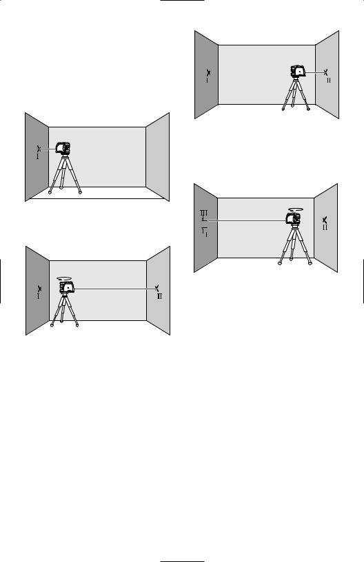
Checking the Horizontal Leveling
Accuracy
A free measuring distance of approximately |
A |
B |
|
78 ft on a firm surface between two walls A |
|
|
|
and B is required for the check. |
|
|
|
– Mount the tool onto the holder or a tripod, |
|
|
|
or place it on a firm and level surface close |
|
|
|
to wall A. Switch the tool on. |
|
|
|
A |
B |
– Align the height of the tool (using the tripod |
|
|
|
or by underlaying, if required) in such a |
|
|
|
manner that the center point of the laser |
|
|
|
beam is projected exactly against the |
|
|
|
previously marked point II on wall B. |
|
78 ft
–Direct the horizontal laser beam against the close wall A and allow the measuring tool to level in. Mark the center of the laser beam on the wall (point I).
A |
180˚ B |
d
A |
B |
180˚
–Turn the tool around by 180°, allow it to level in and mark the center point of the laser beam on the opposite wall
B (point II).
–Without turning the tool, position it close to wall B. Switch the tool on and allow it to level in.
–Rotate the tool by 180° without changing the height. Allow it to level in and mark the center point of the laser beam on wall A (point III). Take care that point III is as vertical as possible above or below point I.
–The difference d of both marked points I and III on wall A indicates the actual height deviation of the tool.
On the measuring distance of 2 x 78 ft = 156 ft, the maximum allowable deviation is:
156 ft x ±0.0036 in/ft = ±9/16 in(.563). Thus, the difference d between points I and III should not exceed 9/16 in (max.).
Checking the Vertical Leveling Accuracy
For this check, a free measuring distance of approx. 13 ft between floor and ceiling on a firm surface is required.
–Draw a straight line on the ceiling.
–Mount the tool to the holder or a tripod. Switch the tool on and rotate it in such a manner that the bottom plumb beam can be seen on the floor.
-8-
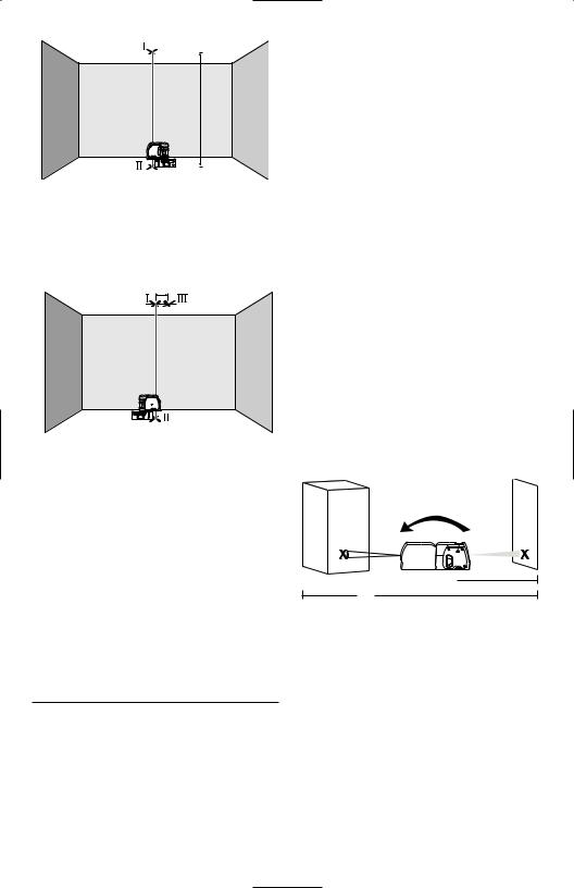
13 ft
–Position the tool in such a manner that the upper plumb beam points against the line on the ceiling. Allow the tool to level in.
Mark the center of the upper laser point on the line on the ceiling (point I). Also, mark the center of the laser point on the floor (point II).
d
–Rotate the tool by 180°. Position it in such a manner that the center of the bottom laser point is directed on the already marked point II and the upper laser point is directed against the line on the ceiling. Allow the tool to level in. Mark the center of the upper laser point on the line on the ceiling (point III).
–The difference d of both marked points I and III on the ceiling results in the actual deviation of the tool to the plumb line.
On the measuring distance of 2 x 13 ft = 26 ft , the maximum allowable deviation is:
26 ft x ±0.0036 in/ft = ±3/16 in.
Thus, the difference d between points I and III should not exceed 3/16 in (max.).
Recalibration Procedure (Front, Up &
Down Beams)
All tools are calibrated when processed through the Bosch quality control program. This process assures that the customer receives a superior product which conforms to the Product Specifications. Although tools have been calibrated before reaching our customers, it contains many precision machined parts which may be affected if the instrument is subjected to abuse. Therefore,
if the device is ever dropped or sustains significant impact, the user should check calibration by following these steps:
Calibrating the Front Beam
1.Choose your recalibration site. To get the most accurate calibration possible, it is best to use two vertical (plumb) surfaces directly opposite each other 100’ apart (50’ minimum).
2.The recalibration process should be done on level ground so that the height of the tool does not change during calibration.
3.Turn the tool off.
4.Remove the calibration plug on the front of tool with a flathead screw-driver.
Set the plug where it will not be lost.
5.Place the tool about 5’ from one of the two vertical surfaces. This will be Surface 1. Turn the tool on.
6.Ensure the tool is level (the laser beam is not blinking).
7.Position the front beam on Surface 1 and mark the dot location Mark A.
8.Turn the tool 180 degrees (make sure you do not change the height) so
that the front laser beam is now visible on the opposing surface, Surface 2. Mark the laser dot position on Surface 2,
Mark B.
Surface 2 |
Surface 1 |
B |
A |
 5ʹ
5ʹ
50ʹ
9.Move the tool to about 5’ from Surface 2 (the location you just marked). Raise or lower the tool so that the laser dot hits the spot you have already marked.
10.Turn the tool 180 degrees (make sure you do not change the height) so
that the front laser beam is now visible on the opposing surface, Surface 1. Mark this new spot, Mark C. You should now have two spots marked on Surface 1. Any difference in height between the two marks is equal to twice the error in calibration. If the two marks are at the same point, the unit does not need to be calibrated. If the two marks are not on the same point, proceed to step 11.
-9-
11.Turn the tool off.
12.Insert the 2mm Allen wrench into the front calibration port. Locate the calibration screw and rotate it in a clockwise direction to lower the beam or in the counter-clockwise direction to raise the beam.
Surface 2 |
Surface 1 |
|
B |
C |
1/2 |
|
||
|
A |
|
|
|
5ʹ
50ʹ
13.Turn the tool on and check the position of the beam to see if it is at a height exactly halfway between the first and second markings made on Surface 1 (where you started). Repeat steps 11 to 13 until the dot is halfway between the two markings.
14.Once this recalibration of the front beam is complete, turn the tool off.
Replace the recalibration plug by pressing it back firmly.
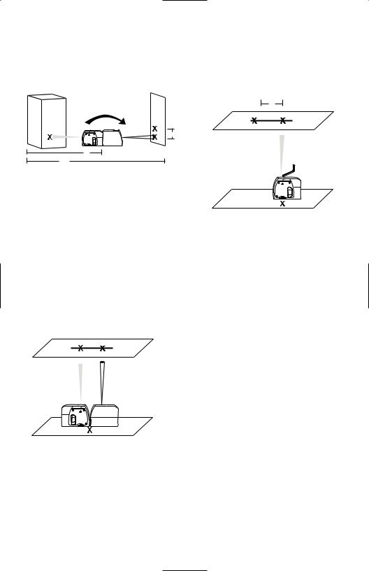
Calibrating the Top and Bottom Beams
15.Choose your recalibration site. To get the most accurate calibration possible, it is best to use a floor/ceiling distance greater than 10’ (the greater distance, the better the accuracy). Floor/Ceiling (top of doorway) distance of approximately 10’.
EF
D
16.Turn the tool off.
17.Remove the calibration plug on the side of tool with a flathead screw-driver.
Set the plug where it will not be lost.
18.Draw a straight line on the ceiling.
19.Turn the tool on.
20.Place the tool on the floor (on its accessory so that you can see the down laser beam on the floor).
21.Align the tool so that the top laser beam hits the line on the ceiling.
22.Mark the down laser beam on the floor, Mark D. Mark the up laser beam on the ceiling, Mark E.
23.Rotate the tool 180 degrees and align the down beam with the mark on the floor.
1
EF
 1/2
1/2
24.Mark the up beam on the ceiling, Mark F. You should have two marks on
the ceiling.
25.Compare the two marks on the ceiling. If the two marks are on the same point, the unit does not need to be calibrated. If the two marks are not on the same point, proceed to step 26.
26.Turn the tool off.
27.Insert the 2mm Allen wrench into the side calibration port. The objective is to get the laser beam halfway between the two marks on the ceiling. Turn the Allen wrench clockwise or counter clockwise to move the laser beam.
28.Turn the tool on and check the
position of the beam to see if it is exactly halfway between the marks on the ceiling. If the beam is not correctly positioned, repeat steps 26–28 until the beam is at the correct position.
29.Plug the side calibration plug on the tool.
30.Calibration is complete.
-10-
Applications
Plumbing a surface
1.Position tool close to the surface to be plumbed.
2.Turn on tool.
3.Measure distance A at a point relatively close to tool and make a note of
the distance.
4.Measure distance B at a point further away from tool and make a note of the distance.
Note: The greater the distance between the two points of measurement, the greater the accuracy.
5.Compare distance A with distance B. If distance A equals distance B, then the surface is plumb. If distance A does not equal distance B, then the surface is not plumb and should be corrected.
Plumb |
B |
A |
Transferring points with the plumb beam
1.Mark the point to be transferred (labeled A in this illustration).
2.Use the Mounting accessory or a Tripod to position the plumb down beam over point A.
3.The plumb up beam will transfer this point along a perfectly vertical axis to point B.
Leveling
1.Adjust the height of tool using the mounting accessory or a tripod so that the horizontal beam hits a reference point (labeled A in this illustration).
2.Rotate tool around its mounting axis to position the front level beam at a point of interest (labeled B in this illustration).
Note: It is possible to use the beam as a leveling instrument without marking a line through beam locations, however, some may find it more satisfying to mark the beam location at a variety of points and then create a straight line through those points to achieve a level line.
Level |
|
A |
B |
|
|
Grading |
|
1.Position tool at the highest point of the surface to be graded.
2.Turn tool on.
3.Measure distance A and make a note of the distance.
4.Measure distance B at distance X away from A and note these distances.
5.Slope = (B – A)/X
Note: To calculate Pitch, set X equal to 12”.
4. Mark point B.
Note: This process may be reversed. Plumb Transfer
B |
A |
Grade |
|
A |
B |
|
|
-11- |
|
 Loading...