


 Loading...
P7P55D EVO
Motherboard

E4647
First Edition (V1)
July 2009
Copyright © 2009 ASUSTeK COMPUTER INC. All Rights Reserved.
No part of this manual, including the products and software described in it, may be reproduced, transmitted, transcribed, stored in a retrieval system, or translated into any language in any form or by any means, except documentation kept by the purchaser for backup purposes, without the express written permission of ASUSTeK COMPUTER INC. (“ASUS”).
Product warranty or service will not be extended if: (1) the product is repaired, modified or altered, unless such repair, modification of alteration is authorized in writing byASUS; or (2) the serial number of the product is defaced or missing.
ASUS PROVIDES THIS MANUAL “AS IS” WITHOUT WARRANTY OF ANY KIND, EITHER EXPRESS OR IMPLIED, INCLUDING BUT NOT LIMITED TO THE IMPLIED WARRANTIES OR CONDITIONS OF MERCHANTABILITY OR FITNESS FOR A PARTICULAR PURPOSE. IN NO EVENT SHALL ASUS, ITS DIRECTORS, OFFICERS, EMPLOYEES OR AGENTS BE LIABLE FOR ANY INDIRECT, SPECIAL, INCIDENTAL, OR CONSEQUENTIAL DAMAGES (INCLUDING DAMAGES FOR LOSS OF PROFITS, LOSS OF BUSINESS, LOSS OF USE OR DATA, INTERRUPTION OF BUSINESS AND THE LIKE), EVEN IF ASUS HAS BEEN ADVISED OF THE POSSIBILITY OF SUCH DAMAGES ARISING FROM ANY DEFECT OR ERROR IN THIS MANUAL OR PRODUCT.
SPECIFICATIONS AND INFORMATION CONTAINED IN THIS MANUAL ARE FURNISHED FOR INFORMATIONAL USE ONLY, AND ARE SUBJECT TO CHANGE AT ANY TIME WITHOUT NOTICE, AND SHOULD NOT BE CONSTRUED AS A COMMITMENT BY ASUS. ASUS ASSUMES NO RESPONSIBILITY OR LIABILITY FOR ANY ERRORS OR INACCURACIES THAT MAY APPEAR IN THIS MANUAL, INCLUDING THE PRODUCTS AND SOFTWARE DESCRIBED IN IT.
Products and corporate names appearing in this manual may or may not be registered trademarks or copyrights of their respective companies, and are used only for identification or explanation and to the owners’ benefit, without intent to infringe.
ii

Contents
Contents...................................................................................................................... |
iii |
Notices ...................................................................................................................... |
viii |
Safety information...................................................................................................... |
ix |
About this guide........................................................................................................... |
x |
P7P55D EVO specifications summary..................................................................... |
xii |
Chapter 1: |
Product introduction |
|
|
1.1 |
Welcome! |
..................................................................................................... |
1-1 |
1.2 |
Package contents....................................................................................... |
1-1 |
|
1.3 |
Special features.......................................................................................... |
1-2 |
|
|
1.3.1 ........................................................................ |
Product highlights |
1-2 |
|
1.3.2 ................................... |
ASUS Xtreme Design—Hybrid Processor |
1-3 |
|
1.3.3 ......................................... |
ASUS Xtreme Design—Hybrid Phase |
1-3 |
|
1.3.4 .............................................. |
ASUS Xtreme Design—Hybrid OS |
1-3 |
|
1.3.5 ............................................................ |
ASUS Exclusive Features |
1-3 |
Chapter 2: |
Hardware information |
|
|
2.1 |
Before you proceed.................................................................................... |
2-1 |
|
2.2 |
Motherboard overview............................................................................... |
2-2 |
|
|
2.2.1 |
Motherboard layout...................................................................... |
2-2 |
|
2.2.2 |
Layout contents........................................................................... |
2-3 |
|
2.2.3 |
Placement direction..................................................................... |
2-4 |
|
2.2.4 |
Screw holes................................................................................. |
2-4 |
2.3 |
Central Processing Unit (CPU).................................................................. |
2-5 |
|
|
2.3.1 |
Installing the CPU........................................................................ |
2-5 |
|
2.3.2 |
Installing the CPU heatsink and fan............................................. |
2-8 |
|
2.3.3 |
Uninstalling the CPU heatsink and fan........................................ |
2-9 |
2.4 |
System memory........................................................................................ |
2-10 |
|
|
2.4.1 |
Overview.................................................................................... |
2-10 |
|
2.4.2 |
Memory configurations.............................................................. |
2-11 |
|
2.4.3 |
Installing a DIMM....................................................................... |
2-19 |
|
2.4.4 |
Removing a DIMM..................................................................... |
2-19 |
2.5 |
Expansion slots........................................................................................ |
2-20 |
|
|
2.5.1 |
Installing an expansion card...................................................... |
2-20 |
|
2.5.2 |
Configuring an expansion card.................................................. |
2-20 |
|
2.5.3 |
Interrupt assignments................................................................ |
2-21 |
|
2.5.4 |
PCI slots.................................................................................... |
2-22 |
|
2.5.5 |
PCI Express 2.0 x1 slots (2.5GT/s)........................................... |
2-22 |
|
2.5.6 |
PCI Express 2.0 x16 slots.......................................................... |
2-22 |
iii

Contents
2.6 |
Onboard switches..................................................................................... |
2-24 |
|
2.7 |
Connectors................................................................................................ |
2-27 |
|
|
2.7.1 |
Rear panel connectors............................................................... |
2-27 |
|
2.7.2 |
Audio I/O connections................................................................ |
2-28 |
|
2.7.3 |
Internal connectors.................................................................... |
2-31 |
|
2.7.4. |
ASUS Q-Connector (system panel)........................................... |
2-40 |
2.8 |
Onboard LEDs........................................................................................... |
2-41 |
|
2.9 |
Starting up for the first time.................................................................... |
2-42 |
|
2.10 |
Turning off the computer......................................................................... |
2-42 |
|
Chapter 3: |
BIOS setup |
|
|
3.1 |
Knowing BIOS............................................................................................. |
3-1 |
|
3.2 |
Updating BIOS............................................................................................ |
3-1 |
|
|
3.2.1 |
ASUS Update utility..................................................................... |
3-2 |
|
3.2.2 |
ASUS EZ Flash 2 utility............................................................... |
3-4 |
|
3.2.3 |
ASUS CrashFree BIOS 3 utility................................................... |
3-5 |
3.3 |
BIOS setup program................................................................................... |
3-6 |
|
|
3.3.1 |
BIOS menu screen...................................................................... |
3-6 |
|
3.3.2 |
Menu bar...................................................................................... |
3-6 |
|
3.3.3 |
Navigation keys........................................................................... |
3-7 |
|
3.3.4 |
Menu items.................................................................................. |
3-7 |
|
3.3.5 |
Submenu items............................................................................ |
3-7 |
|
3.3.6 |
Configuration fields...................................................................... |
3-7 |
|
3.3.7 |
Pop-up window............................................................................ |
3-7 |
|
3.3.8 |
Scroll bar...................................................................................... |
3-7 |
|
3.3.9 |
General help................................................................................ |
3-7 |
3.4 |
Main menu................................................................................................... |
3-8 |
|
|
3.4.1 |
SATA 1-6...................................................................................... |
3-8 |
|
3.4.2 |
Storage Configuration................................................................ |
3-10 |
|
3.4.3 |
AHCI Configuration.................................................................... |
3-11 |
|
3.4.4 |
System Information.................................................................... |
3-11 |
3.5 |
Ai Tweaker menu...................................................................................... |
3-12 |
|
|
3.5.1 |
Ai Overclock Tuner [Auto].......................................................... |
3-12 |
|
3.5.2 |
CPU Ratio Setting [Auto]........................................................... |
3-13 |
|
3.5.3 |
Intel(R) SpeedStep(TM) Tech [Enabled].................................... |
3-13 |
|
3.5.4 |
DRAM Frequency [Auto]............................................................ |
3-14 |
|
3.5.5 |
PQI Frequency [Auto]................................................................ |
3-14 |
iv

Contents
|
3.5.6 |
DRAM Timing Control................................................................ |
3-14 |
|
3.5.7 |
Intel(R) TurboMode Tech [Enabled]........................................... |
3-14 |
|
3.5.8 |
Xtreme Phase Full Power Mode [Auto]...................................... |
3-14 |
|
3.5.9 |
BCLK Frequency [XXX]............................................................. |
3-14 |
|
3.5.10 |
PCIE Frequency [XXX].............................................................. |
3-14 |
|
3.5.11 |
CPU Differential Amplitude [Auto].............................................. |
3-16 |
|
3.5.12 |
CPU Clock Skew [Auto]............................................................. |
3-16 |
|
3.5.13 |
CPU Voltage Mode [Offset] ....................................................... |
3-17 |
|
3.5.14 |
IMC Voltage [Auto] .................................................................... |
3-17 |
|
3.5.15 |
DRAM Voltage [Auto]................................................................. |
3-17 |
|
3.5.16 |
CPU PLL Voltage [Auto]............................................................ |
3-17 |
|
3.5.17 |
PCH Voltage [Auto].................................................................... |
3-18 |
|
3.5.18 |
DRAM DATA REF Voltage on CHA/B [Auto].............................. |
3-18 |
|
3.5.19 |
Load-Line Calibration [Auto]...................................................... |
3-18 |
|
3.5.20 |
CPU Spread Spectrum [Auto].................................................... |
3-18 |
|
3.5.21 |
PCIE Spread Spectrum [Auto]................................................... |
3-18 |
3.6 |
Advanced menu........................................................................................ |
3-19 |
|
|
3.6.1 |
CPU Configuration..................................................................... |
3-19 |
|
3.6.2 |
North Bridge Configuration........................................................ |
3-21 |
|
3.6.3 |
Onboard Devices Configuration................................................. |
3-22 |
|
3.6.4 |
USB Configuration..................................................................... |
3-23 |
|
3.6.5 |
PCIPnP...................................................................................... |
3-24 |
|
3.6.6 |
Intel VT-d [Disabled].................................................................. |
3-24 |
|
3.6.7 |
T.Probe [Enabled]...................................................................... |
3-24 |
3.7 |
Power menu.............................................................................................. |
3-25 |
|
|
3.7.1 |
Suspend Mode [Auto]................................................................ |
3-25 |
|
3.7.2 |
Repost Video on S3 Resume [No]............................................. |
3-25 |
|
3.7.3 |
ACPI 2.0 Support [Disabled]...................................................... |
3-25 |
|
3.7.4 |
ACPI APIC Support [Enabled]................................................... |
3-25 |
|
3.7.5 |
EuP Ready [Disabled]................................................................ |
3-25 |
|
3.7.6 |
APM Configuration..................................................................... |
3-26 |
|
3.7.7 |
Hardware Monitor...................................................................... |
3-27 |
3.8 |
Boot menu................................................................................................. |
3-28 |
|
|
3.8.1 |
Boot Device Priority................................................................... |
3-28 |
|
3.8.2 |
Boot Settings Configuration....................................................... |
3-29 |
|
3.8.3 |
Security...................................................................................... |
3-30 |

Contents
3.9 |
Tools menu................................................................................................ |
3-32 |
|
|
3.9.1 |
ASUS O.C. Profile..................................................................... |
3-32 |
|
3.9.2 |
Drive Xpert Configuration.......................................................... |
3-33 |
|
3.9.3 |
AI NET 2.................................................................................... |
3-35 |
|
3.9.4 |
ASUS EZ Flash 2....................................................................... |
3-35 |
|
3.9.5 |
Express Gate [Auto]................................................................... |
3-35 |
3.10 |
Exit menu................................................................................................... |
3-36 |
|
Chapter 4: |
Software support |
|
|
4.1 |
Installing an operating system.................................................................. |
4-1 |
|
4.2 |
Support DVD information........................................................................... |
4-1 |
|
|
4.2.1 |
Running the support DVD............................................................ |
4-1 |
|
4.2.2 |
Obtaining the software manuals.................................................. |
4-2 |
4.3 |
Software information.................................................................................. |
4-3 |
|
|
4.3.1 |
ASUS PC Probe II....................................................................... |
4-3 |
|
4.3.2 |
ASUS AI Suite.............................................................................. |
4-4 |
|
4.3.3 |
ASUS Fan Xpert.......................................................................... |
4-5 |
|
4.3.4 |
ASUS EPU................................................................................... |
4-6 |
|
4.3.5 |
ASUS Express Gate.................................................................... |
4-7 |
|
4.3.6 |
VIA® High DefinitionAudio utility.................................................. |
4-8 |
|
4.3.7 |
ASUS Drive Xpert........................................................................ |
4-9 |
4.4 |
ASUS Unique Overclocking Utility—TurboV EVO................................. |
4-10 |
|
|
4.4.1 |
Using ASUS TurboV.................................................................. |
4-10 |
|
4.4.2 |
Using ASUS TurboV Auto Tuning Mode.................................... |
4-11 |
|
4.4.3 |
Using ASUS Turbo Key.............................................................. |
4-12 |
4.5 |
RAID configurations................................................................................. |
4-13 |
|
|
4.5.1 |
RAID definitions......................................................................... |
4-13 |
|
4.5.2 |
Installing Serial ATA hard disks.................................................. |
4-14 |
|
4.5.3 |
Setting the RAID item in BIOS................................................... |
4-14 |
|
4.5.4 |
Intel® Matrix Storage Manager option ROM utility..................... |
4-14 |
4.6 |
Creating a RAID driver disk..................................................................... |
4-18 |
|
|
4.6.1 |
Creating a RAID driver disk without entering the OS................. |
4-18 |
|
4.6.2 |
Creating a RAID driver disk in Windows®.................................. |
4-18 |
|
4.6.3 |
Installing the RAID driver during Windows® OS installation....... |
4-18 |
|
4.6.4 |
Using a USB floppy disk drive................................................... |
4-19 |
vi

Contents
Chapter 5: |
Multiple GPU technology support |
|
|
5.1 |
ATI® CrossFireX™ technology................................................................... |
5-1 |
|
|
5.1.1 |
Requirements.............................................................................. |
5-1 |
|
5.1.2 |
Before you begin.......................................................................... |
5-1 |
|
5.1.3 |
Installing two CrossFireX™ graphics cards................................. |
5-2 |
|
5.1.4 |
Installing three CrossFireX™ graphics cards.............................. |
5-3 |
|
5.1.5 |
Installing the device drivers......................................................... |
5-4 |
|
5.1.6 |
Enabling the ATI® CrossFireX™ technology................................ |
5-4 |
5.2 |
NVIDIA® SLI™ technology.......................................................................... |
5-6 |
|
|
5.2.1 |
Requirements.............................................................................. |
5-6 |
|
5.2.2 |
Installing two SLI-ready graphics cards....................................... |
5-6 |
|
5.2.3 |
Installing the device drivers......................................................... |
5-7 |
|
5.2.4 |
Enabling the NVIDIA® SLI™ technology...................................... |
5-7 |
vii
Notices
Federal Communications Commission Statement
This device complies with Part 15 of the FCC Rules. Operation is subject to the following two conditions:
•This device may not cause harmful interference, and
•This device must accept any interference received including interference that may cause undesired operation.
This equipment has been tested and found to comply with the limits for a Class B digital device, pursuant to Part 15 of the FCC Rules. These limits are designed to provide reasonable protection against harmful interference in a residential installation. This equipment generates, uses and can radiate radio frequency energy and, if not installed and used in accordance with manufacturer’s instructions, may cause harmful interference to radio communications. However, there is no guarantee that interference will not occur in a particular installation. If this equipment does cause harmful interference to radio or
television reception, which can be determined by turning the equipment off and on, the user is encouraged to try to correct the interference by one or more of the following measures:
•Reorient or relocate the receiving antenna.
•Increase the separation between the equipment and receiver.
•Connect the equipment to an outlet on a circuit different from that to which the receiver is connected.
•Consult the dealer or an experienced radio/TV technician for help.
The use of shielded cables for connection of the monitor to the graphics card is required to assure compliance with FCC regulations. Changes or modifications to this unit not expressly approved by the party responsible for compliance could void the user’s authority to operate this equipment.
Canadian Department of Communications Statement
This digital apparatus does not exceed the Class B limits for radio noise emissions from digital apparatus set out in the Radio Interference Regulations of the Canadian Department of Communications.
This class B digital apparatus complies with Canadian ICES-003.
REACH
Complying with the REACH (Registration, Evaluation, Authorisation, and Restriction of Chemicals) regulatory framework, we published the chemical substances in our products at ASUS REACH website at http://green.asus.com/english/REACH.htm.
DO NOT throw the motherboard in municipal waste. This product has been designed to enable proper reuse of parts and recycling. This symbol of the crossed out wheeled bin indicates that the product (electrical and electronic equipment) should not be placed in municipal waste. Check local regulations for disposal of electronic products.
DO NOT throw the mercury-containing button cell battery in municipal waste. This symbol of the crossed out wheeled bin indicates that the battery should not be placed in municipal waste.
viii
Safety information
Electrical safety
•To prevent electrical shock hazard, disconnect the power cable from the electrical outlet before relocating the system.
•When adding or removing devices to or from the system, ensure that the power cables for the devices are unplugged before the signal cables are connected. If possible, disconnect all power cables from the existing system before you add a device.
•Before connecting or removing signal cables from the motherboard, ensure that all power cables are unplugged.
•Seek professional assistance before using an adapter or extension cord. These devices could interrupt the grounding circuit.
•Ensure that your power supply is set to the correct voltage in your area. If you are not sure about the voltage of the electrical outlet you are using, contact your local power company.
•If the power supply is broken, do not try to fix it by yourself. Contact a qualified service technician or your retailer.
•The optical S/PDIF is an optional component (may or may not be included in your motherboard) and is defined as a CLASS 1 LASER PRODUCT.
INVISIBLE LASER RADIATION, AVOID EXPOSURE TO BEAM.
•Never dispose of the battery in fire. It could explode and release harmful substances into the environment.
•Never dispose of the battery with your regular household waste. Take it to a hazardous material collection point.
•Never replace the battery with an incorrect battery type.
•RISK OF EXPLOSION IF BATTERY IS REPLACED BY AN INCORRECT TYPE.
•DISPOSE OF USED BATTERIES ACCORDING TO THE ABOVE BATTERY-RELATED INSTRUCTIONS.
Operation safety
•Before installing the motherboard and adding devices on it, carefully read all the manuals that came with the package.
•Before using the product, ensure all cables are correctly connected and the power cables are not damaged. If you detect any damage, contact your dealer immediately.
•To avoid short circuits, keep paper clips, screws, and staples away from connectors, slots, sockets and circuitry.
•Avoid dust, humidity, and temperature extremes. Do not place the product in any area where it may become wet.
This motherboard should only be used in environments with ambient temperatures between 5°C (41°F) and 40°C (104°F).
•Place the product on a stable surface.
•If you encounter technical problems with the product, contact a qualified service technician or your retailer.
ix

About this guide
Thisuserguidecontainstheinformationyouneedwheninstallingandconfiguringthemotherboard.
How this guide is organized
This guide contains the following parts:
•Chapter 1: Product introduction
This chapter describes the features of the motherboard and the new technology it supports.
•Chapter 2: Hardware information
This chapter lists the hardware setup procedures that you have to perform when installing system components. It includes description of the switches, jumpers, and connectors on the motherboard.
•Chapter 3: BIOS setup
This chapter tells how to change system settings through the BIOS Setup menus. Detailed descriptions of the BIOS parameters are also provided.
•Chapter 4: Software support
This chapter describes the contents of the support DVD that comes with the motherboard package and the software.
•Chapter 5: Multiple GPU technology support
This chapter describes how to install and configure multipleATI® CrossFireX™ and NVIDIA® SLI™ graphics cards.
Where to find more information
Refer to the following sources for additional information and for product and software updates.
1.ASUS websites
The ASUS website provides updated information on ASUS hardware and software products. Refer to the ASUS contact information.
2.Optional documentation
Your product package may include optional documentation, such as warranty flyers, that may have been added by your dealer. These documents are not part of the standard package.
Conventions used in this guide
To ensure that you perform certain tasks properly, take note of the following symbols used throughout this manual.
DANGER/WARNING: Information to prevent injury to yourself when trying to complete a task.
CAUTION: Information to prevent damage to the components when trying to complete a task.
IMPORTANT: Instructions that you MUST follow to complete a task.
NOTE: Tips and additional information to help you complete a task.
Typography
Bold text |
Indicates a menu or an item to select. |
Italics |
Used to emphasize a word or a phrase. |
<Key> |
Keys enclosed in the less-than and greater-than sign means |
|
that you must press the enclosed key. |
|
Example: <Enter> means that you must press the Enter or |
|
Return key. |
<Key1> + <Key2> + <Key3> |
If you must press two or more keys simultaneously, the key |
|
names are linked with a plus sign (+). |
|
Example: <Ctrl> + <Alt> + <Del> |
xi
P7P55D EVO specifications summary
CPU
Chipset
Memory
Expansion slots
Multi-GPU support
Storage
LAN
USB
IEEE 1394
Audio
LGA1156 socket for Intel® Core™ i7 / Core™ i5 Processors Supports Intel® Turbo Boost Technology
* Refer to www.asus.com for Intel CPU support list
Intel® P55 Express Chipset
4 x DIMM, max. 16GB, DDR3 2133(O.C.)* / 1600 / 1333 /
1066 MHz, non-ECC, un-buffered memory
Dual channel memory architecture
Supports Intel® Extreme Memory Profile (XMP)
* Hyper DIMM support is subject to the physical characteristics of individual CPUs.
** Refer to www.asus.com or this user manual for the Memory
QVL (Qualified Vendors Lists)
2 x PCI Express 2.0 x16 slots (single at x16 or dual at x8 / x8 mode) 1 x PCI Express 2.0 x16 slot (at x4 mode, 2.5GT/s)
2 x PCI Express 2.0 x1 slots (2.5GT/s)
2 x PCI slots
Supports NVIDIA® Quad-GPU SLI™ Technology
Supports ATI® Quad-GPU CrossFireX™ Technology
Intel® P55 Express Chipset
- 6 x SATA 3.0 Gb/s ports
- Intel® Matrix Storage Technology supports SATA RAID 0, 1, 5, and 10
JMicron® JMB363 SATA & PATA controller
- 1 x Ultra DMA 133/100/66 for up to 2 PATA devices - 1 x External SATA 3.0 Gb/s port (SATA On-the-Go)
JMicron® JMB322 controller (Drive Xpert Technology)
- 2 x SATA 3.0 Gb/s ports (dark blue and gray)
- Supports EZ Backup and Super Speed functions
* Drive Xpert function is available only when the hard disk drives are set as data drives.
Dual Gigabit LAN controllers
Realtek® 8112L / 8110SC Gigabit LAN controller featuring AI NET2
14 x USB 2.0 ports (6 ports at mid-board, 8 ports at back panel)
VIA® VT6308P controller supports 2 x IEEE 1394a ports (one at midboard, one at back panel)
VIA® VT1828S 8-channel High DefinitionAudio CODEC
- Absolute Pitch BD192/24
- DTS Surround Sensation UltraPC
- Supports Jack-Detection, Multi-streaming, and
Front Panel Jack-Retasking
- Coaxial / Optical S/PDIF out ports at back I/O
(continued on the next page)
xii

P7P55D EVO specifications summary
ASUS unique features |
ASUS Hybrid Processor – TurboV EVO |
|
|
- Auto Tuning, TurboV and Turbo Key |
|
|
ASUS Hybrid Phase |
|
|
- T.Probe Technology for Active Cooling |
|
|
- 12+2 Phase Power Design |
|
|
ASUS Hybrid OS – Express Gate |
|
|
ASUS Xtreme Design |
|
|
ASUS Exclusive Features |
|
|
- |
ASUS Drive Xpert |
|
- |
MemOK! |
|
- |
ASUS EPU |
|
ASUS Quiet Thermal Solutions |
|
|
- ASUS Fanless Design: Heat-pipe solution |
|
|
- ASUS Fanless Design: Stack Cool 3 |
|
|
- |
ASUS Fan Xpert |
|
ASUS Crystal Sound |
|
|
- |
ASUS Noise Filter |
|
ASUS EZ DIY |
|
|
- |
ASUS Q-Shield |
|
- |
ASUS Q-Connector |
|
- |
ASUS O.C. Profile |
|
- ASUS CrashFree BIOS 3 |
|
|
- ASUS EZ Flash 2 |
|
|
- |
ASUS MyLogo 2™ |
|
- Multi-language BIOS |
|
ASUS Q-Design |
ASUS Q-LED (CPU, DRAM, VGA, Boot Device LED) |
|
|
ASUS Q-Slot |
|
|
ASUS Q-DIMM |
|
ASUS exclusive |
Precision Tweaker 2 |
|
overclocking features |
- |
vCore: Adjustable CPU voltage at 0.00625V increment |
|
- vIMC: Adjustable IMC voltage at 0.00625V increment |
|
|
- vDRAM Bus: 81-step DRAM bus voltage control |
|
|
- vPCH: 2-step chipset voltage control |
|
|
- vCPU_PLL: 4-step reference voltage control |
|
|
SFS (Stepless Frequency Selection) |
|
|
- Internal Base Clock tuning from 80MHz up to 500MHz at |
|
|
|
1MHz increment |
|
- PCI Express frequency tuning from 100MHz up to 200MHz |
|
|
|
at 1MHz increment |
|
Overclocking protection |
|
|
- ASUS C.P.R. (CPU Parameter Recall) |
|
|
(continued on the next page) |
|
xiii
P7P55D EVO specifications summary
Back panel I/O ports
Internal I/O connectors
BIOS features
Manageability
Support DVD contents
Form factor
1 x PS/2 keyboard port (purple)
1 x PS/2 mouse port (green)
1 x Clear CMOS button
1 x Coaxial S/PDIF Out port
1 x Optical S/PDIF Out port
1 x IEEE 1394a port
1 x External SATA port
2 x LAN (RJ-45) ports
8 x USB 2.0/1.1 ports
8-channel Audio I/O ports
3 x USB connectors support additional 6 USB ports
1 x IDE connector
6 x SATA connectors
2 x Drive Xpert SATA connectors (dark blue and gray) 1 x CPU Fan connector
2 x Chassis Fan connectors (1 x 4-pin, 1 x 3-pin) 1 x Power Fan connector
1 x IEEE1394a connector
1 x COM connector
Front panel audio connector 1 x S/PDIF Out header
CD audio in
24-pin ATX Power connector
8-pin EATX 12V Power connector System Panel (Q-Connector)
1 x MemOK! button
1 x Power on switch
1 x Reset switch
16 Mb Flash ROM, AMI BIOS, PnP, DMI 2.0, WfM 2.0, SM BIOS 2.5, ACPI 2.0a, Multi-language BIOS, ASUS EZ Flash 2, ASUS CrashFree BIOS 3
WfM 2.0, DMI 2.0, WOL by PME, WOR by PME, PXE
Drivers
ASUS Utilities
ASUS Update
Anti-virus software (OEM version)
ATX form factor: 12 in. x 9.6 in. (30.5 cm x 24.4 cm)
*Specifications are subject to change without notice.
xiv
Chapter 1
Chapter 1: |
Product introduction |
1.1Welcome!
Thank you for buying an ASUS® P7P55D EVO motherboard!
The motherboard delivers a host of new features and latest technologies, making it another standout in the long line of ASUS quality motherboards!
Before you start installing the motherboard, and hardware devices on it, check the items in your package with the list below.
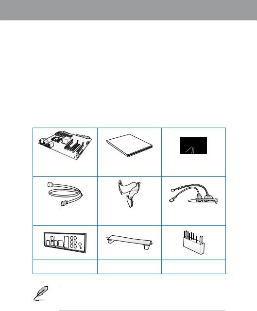
1.2Package contents
Check your motherboard package for the following items.
Chapter 1
Manual
User
ASUS P7P55D EVO |
User guide |
Support DVD |
|
motherboard |
|||
|
|
4 x Serial ATA 3.0 Gb/s cables |
1 x Ultra DMA 133/ |
1 x 2-port USB 2.0 and 1-port |
|
100/66 cable |
eSATA module |
||
|
1 x ASUS Q-Shield |
1 x ASUS SLI™ bridge |
|
connector |
||
|
1 x 2-in-1 ASUS Q-Connector
kit
•If any of the above items is damaged or missing, contact your retailer.
•The illustrated items above are for reference only.Actual product specifications may vary with different models.
ASUS P7P55D EVO |
1-1 |

1 Chapter
1.3Special features
1.3.1Product highlights
Intel® LGA1156 Lynnfield Processor Ready
This motherboard supports the latest Intel® Lynnfield processors in LGA1156 package, which has memory and PCI Express controller integrated to support 2-channel (4 DIMMs) DDR3 memory and 16 PCI Express 2.0 lanes, providing great graphics performance. Intel® Lynnfield processor is one of the most powerful and energy efficient CPU in the world. Refer to page
2-5 for details.
Intel® P55
The Intel® P55 Express Chipset is the latest one-chipset design to support the latest 1156 socket Intel® Core™ i7 / Core™ i5 processors. Intel® P55 provides improved performance by utilizing serial point-to-point links, allowing increased bandwidth and stability.
PCIe 2.0
This motherboard supports the latest PCIe 2.0 devices for double speed and bandwidth that enhances system performance. Refer to page 2-22 for details.
Quad-GPU SLI™ and Quad-GPU CrossFireX™ support!
P7P55D EVO brings you the multi-GPU choice of either SLI™ or CrossFireX™. The motherboard features the most powerful Intel® P55 platform to optimize PCIe allocation in multiple GPU configurations. Expect a brand-new gaming style you’ve never experienced before! Refer to Chapter 5 for details.
Dual-Channel DDR3 2133(O.C.) / 1600 / 1333 / 1066 support
The motherboard supports DDR3 memory that features data transfer rates of 2133(O.C.) /
1600 / 1333 / 1066 MHz to meet the higher bandwidth requirements of the latest 3D graphics, multimedia, and Internet applications. The dual-channel DDR3 architecture enlarges the bandwidth of your system memory to boost system performance. Refer to page 2-10 for details.
Green ASUS
This motherboard and its packaging comply with the European Union’s Restriction on the use of Hazardous Substances (RoHS). This is in line with theASUS vision of creating environment-friendly and recyclable products/packaging to safeguard consumers’ health while minimizing the impact on the environment.
1-2 |
Chapter 1: Product Introduction |

1.3.2ASUS Xtreme Design—Hybrid Processor
TurboV EVO
The ultimate O.C. processor satisfies every level of overclockers—from die-hard enthusiasts to beginners. Auto tuning intelligently pushes the system to the fastest clock speeds while maintaining stability. Turbo Key boosts performance with just one touch; while TurboV offers more options to advanced overclockers to achieve world O.C. record. Refer to page 4-10 for details.
Auto Tuning
Auto Tuning is an intelligent tool that automates overclocking to achieve a total system level up. This tool also provides stability testing. Even O.C. beginners can achieve extreme yet stable overclocking results with Auto Tuning! Refer to page 4-11 for details.
1.3.3ASUS Xtreme Design—Hybrid Phase
T.Probe
The T.Probe microchip detects and balances power phase loading and temperature in realtime. This feature optimizes the power phase functions, allowing components to run at lower temperatures and extending their lifespan.
ASUS 12+2 Phase Power Design
The groundbreaking 12+2 phase VRM design is brought to the ASUS motherboards. 12+2 phase power design, 12-phase for vCore and extra 2-phase for Memory controller inside
CPU can provide the highest power efficiency, and hence generates less heat to effectively enhance the overclocking capability. With the high quality power components such as low RDS (on) MOSFETs, Ferrite core chokes with lower hysteresis loss and 100% Japan-made high quality conductive polymer capacitors, ASUS 12+2 phase VRM design also ensure longer component life and minimum power loss.
1.3.4ASUS Xtreme Design—Hybrid OS
Express Gate
Express Gate is an ASUS exclusive OS that provides you with quick access to the Internet and key applications before entering the Windows® OS. Refer to page 3-35 and 4-7 for details.
1.3.5ASUS Exclusive Features
ASUS Drive Xpert
Without BIOS setups, the ASUS exclusive Drive Xpert is ideal for anyone who needs to secure data on their hard drives or enhance hard drive performances without the hassles of complicated configurations. With Drive Xpert’s user-friendly graphical user interface, you can easily arrange hard drive backups or enhance their hard drive transfer rates—ensuring that data is looked after every moment, every day. Refer to page 2-33, 3-33 and 4-9 for details.
Chapter 1
ASUS P7P55D EVO |
1-3 |

1 Chapter
MemOK!
Memory compatibility is among the top concerns during computer upgrades. Worry no more. MemOK! is the fastest memory booting solution today. This remarkable memory rescue tool requires nothing but a push of a button to patch memory issues and get your system up and running in no time. The technology is able to determine failsafe settings that can dramatically improve your system booting success. Refer to page 2-25 for details.
ASUS EPU
The ASUS EPU (Energy Processing Unit) provides total system power management by detecting current PC loadings and intelligently moderating power usage for critical PC components in real-time–helping save power and money! Refer to page 4-6 for details.
ASUS Quiet Thermal Solutions
ASUS Quiet Thermal solution makes system more stable and enhances the overclocking capability.
ASUS Fanless Design—Heat-pipe solution
The Heat Pipe design effectively directs the heat generated by the vCore area to the heatsink near the back IO ports, where it can be carried away by existing airflow from
CPU fan. The purpose of the innovative heat pipe design on this motherboard is that the groundbreaking fanless design does not have lifetime problems as a chipset fan does. The Heat Pipe design is the most reliable fanless thermal solution to date.
DO NOT uninstall the heat-pipe by yourself. Doing so may bend the tubing and affect the heat dissipation performance.
Fan Xpert
ASUS Fan Xpert intelligently allows you to adjust both the CPU and chassis fan speeds according to different ambient temperatures caused by different climate conditions
in different geographic regions and your PC’s loading. The built-in variety of useful profiles offer flexible controls of fan speed to achieve a quiet and cool environment.
Refer to page 4-5 for details.
ASUS Crystal Sound
This feature can enhance speech-centric applications like Skype, online game, video conference and recording.
ASUS Noise Filter
This feature detects repetitive and stationary noises like computer fans, air conditioners, and other background noises then eliminates it in the incoming audio stream while recording.
1-4 |
Chapter 1: Product Introduction |

DTS Surround Sensation UltraPC
DTS Surround Sensation UltraPC delivers exceptional 5.1 surround experience through the most common PC audio setups—your existing stereo speakers or headphones. In addition to virtual surround, “Bass enhancement” provides stronger low frequency bass sound, and “Voice clarification” provides clear human dialogue even with loud background sound. With these technologies, you may experience a better home-theater audio with ease.
ASUS EZ DIY
ASUS EZ DIY feature collection provides you with easy ways to install computer components, update the BIOS or back up your favorite settings.
ASUS Onboard Switch
With an easy press during overclocking, the exclusive onboard switches allow gamers to effortless fine-tune the performance without having to short the pins! Refer to page
2-24 for details.
ASUS Q-Design
ASUS Q-Design enhances your DIY experience. All of Q-LED, Q-Slot and Q-DIMM design speed up and simplify the DIY process!
ASUS Q-Shield
ASUS Q-Shield’s special design makes it convenient and easy to install on your motherboard. With better electric conductivity, it ideally protects your motherboard against static electricity and shields it against Electronic Magnetic Interference (EMI).
ASUS Q-Connector
ASUS Q-Connector allows you to easily connect or disconnect the chassis front panel cables to the motherboard. This unique module eliminates the trouble of connecting the system panel cables one at a time and avoiding wrong cable connections. Refer to page 2-40 for details.
ASUS EZ-Flash 2
ASUS EZ Flash 2 is a user-friendly utility that allows you to update the BIOS without using a bootable floppy disk or an OS-based utility. Refer to page 3-4 for details.
ASUS O.C. Profile
The motherboard features theASUS O.C. Profile that allows you to conveniently store or load multiple BIOS settings. The BIOS settings can be stored in the CMOS or a separate file, giving you the freedom to share and distribute your favorite settings.
Refer to page 3-32 for details.
ASUS MyLogo2™
This feature allows you to convert your favorite photo into a 256-color boot logo for a more colorful and vivid image on your screen.
ASUS Multi-language BIOS
The multi-language BIOS allows you to select the language of your choice from the available options. The localized BIOS setup menu helps you configure your system easier and faster.
Chapter 1
ASUS P7P55D EVO |
1-5 |

1 Chapter
1-6 |
Chapter 1: Product Introduction |
Chapter 2
Chapter 2: |
Hardware information |
2.1Before you proceed
Take note of the following precautions before you install motherboard components or change any motherboard settings.
•Unplug the power cord from the wall socket before touching any component.
• Before handling components, use a grounded wrist strap or touch a safely grounded object or a metal object, such as the power supply case, to avoid damaging them due to static electricity.
•Hold components by the edges to avoid touching the ICs on them.
•Whenever you uninstall any component, place it on a grounded antistatic pad or in the bag that came with the component.
•Before you install or remove any component, ensure that the ATX power supply is switched off or the power cord is detached from the power supply. Failure to do so may cause severe damage to the motherboard, peripherals, or components.
Chapter 2
ASUS P7P55D EVO |
2-1 |

2.2Motherboard overview
2.2.1Motherboard layout
2 Chapter
Refer to 2.7 Connectors for more information about rear panel connectors and internal connectors.
2-2 |
Chapter 2: Hardware information |

2.2.2Layout contents
Connectors/Jumpers/Slots |
Page |
|
1. |
ATX power connectors (24-pin EATXPWR, 8-pin EATX12V) |
2-38 |
2. |
LGA1156 CPU Socket |
2-5 |
3. |
DDR3 DIMM slots |
2-10 |
4. |
DRAM overvoltage setting switch (OV_DRAM) |
2-26 |
5. |
CPU, chassis, and power fan connectors (4-pin CPU_FAN, |
2-36 |
|
4-pin CHA_FAN1, 3-pin CHA_FAN2, 3-pin PWR_FAN) |
|
6. |
Serial port connector (10-1 pin COM1) |
2-35 |
7. |
MemOK! switch |
2-25 |
8. |
IDE connector (40-1 pin PRI_EIDE) |
2-31 |
9. |
Intel® P55 Serial ATA 3.0 Gb/s connectors (7-pin SATA1–6 [Blue]) |
2-32 |
10. |
JMicron® JMB322 Serial ATA RAID connectors |
2-33 |
|
(7-pin SATA_E1 [gray], 7-pin SATA_E2 [dark blue]) |
|
11. |
System panel connector (20-8 pin PANEL) |
2-39 |
12. |
USB connectors (10-1 pin USB910, USB1112, USB1314) |
2-34 |
13. |
Reset switch |
2-24 |
14. |
Power-on switch |
2-24 |
15. |
IEEE 1394a port connector (10-1 pin IE1394_2) |
2-35 |
16. |
Optical drive audio connector (4-pin CD) |
2-34 |
17. |
Front panel audio connector (10-1 pin AAFP) |
2-37 |
18. |
Digital audio connector (4-1 pin SPDIF_OUT) |
2-37 |
Chapter 2
ASUS P7P55D EVO |
2-3 |
2 Chapter
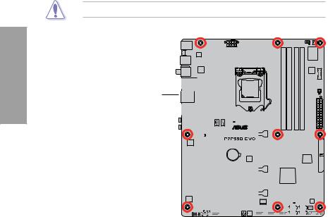
2.2.3Placement direction
When installing the motherboard, ensure that you place it into the chassis in the correct orientation. The edge with external ports goes to the rear part of the chassis as indicated in the image below.
2.2.4Screw holes
Place nine screws into the holes indicated by circles to secure the motherboard to the chassis.
DO NOT overtighten the screws! Doing so can damage the motherboard.
Place this side towards 
 the rear of the chassis
|
|
|
|
|
|
|
|
|
|
|
|
|
|
|
|
|
|
|
|
|
|
|
|
|
|
|
|
|
|
|
|
|
|
|
|
|
|
|
|
|
|
|
|
|
|
|
|
|
|
|
|
|
|
|
|
|
|
|
|
|
|
|
|
|
|
|
|
|
|
|
|
|
|
|
|
|
|
|
|
|
|
|
|
|
|
|
|
|
|
|
|
|
|
|
|
|
|
|
|
|
|
|
|
|
|
|
|
|
|
|
|
|
|
|
|
|
|
|
|
|
|
|
|
|
|
|
|
|
|
|
|
|
|
|
|
|
|
|
|
|
|
|
|
|
|
|
|
|
|
|
|
|
|
|
|
|
|
|
|
|
|
|
|
|
|
|
|
|
|
|
|
|
|
|
|
|
|
|
|
|
|
|
|
|
|
|
|
|
|
|
|
|
|
|
|
|
|
|
|
|
|
|
|
|
|
|
|
|
|
|
|
|
|
|
|
|
|
|
|
|
|
|
|
|
|
|
|
|
|
|
|
|
|
|
|
|
|
|
|
|
|
|
|
|
|
|
|
|
|
|
|
|
|
|
|
|
|
|
|
|
|
|
|
|
|
|
|
|
|
|
|
|
|
|
|
|
|
|
|
|
|
|
|
|
|
|
|
|
|
|
|
|
|
|
|
|
|
|
|
|
|
|
|
|
|
|
|
|
|
|
|
|
|
|
|
|
|
|
|
|
|
|
|
|
|
|
|
|
|
|
|
|
|
|
|
|
|
|
|
|
|
|
|
|
|
|
|
|
|
|
|
|
|
|
|
|
|
|
|
|
|
|
|
|
|
|
|
|
|
|
|
|
|
|
|
|
|
|
|
|
|
|
|
|
|
|
|
|
|
|
|
|
|
|
|
|
|
|
|
|
|
|
|
|
|
|
|
|
|
|
|
|
|
|
|
|
|
|
|
|
|
|
|
|
|
|
|
|
|
|
|
|
|
|
|
|
|
|
|
|
|
|
|
|
|
|
|
|
|
|
|
|
|
|
|
|
|
|
|
|
|
|
|
|
|
|
|
|
|
|
|
|
|
|
|
|
|
|
|
|
|
|
|
|
|
|
|
|
|
|
|
|
|
|
|
|
|
|
|
|
|
|
|
|
|
|
|
|
|
|
|
|
|
|
|
|
|
|
|
|
|
|
|
|
|
|
|
|
|
|
|
|
|
|
|
|
|
|
|
|
|
|
|
|
|
|
|
|
|
|
|
|
|
|
|
|
|
|
|
|
|
|
|
|
|
|
|
|
|
|
|
2-4 |
|
|
|
|
|
|
Chapter 2: Hardware information |
||||||||||||||||||
2.3Central Processing Unit (CPU)
The motherboard comes with a surface mount LGA1156 socket designed for the Intel® Core™ i7 / Core™ i5 processor.
Ensure that all power cables are unplugged before installing the CPU.
•Upon purchase of the motherboard, ensure that the PnP cap is on the socket and the socket contacts are not bent. Contact your retailer immediately if the PnP cap is missing, or if you see any damage to the PnP cap/socket contacts/motherboard components. ASUS will shoulder the cost of repair only if the damage is shipment/ transit-related.
•Keep the cap after installing the motherboard. ASUS will process Return Merchandise
Authorization (RMA) requests only if the motherboard comes with the cap on the
LGA1156 socket.
•The product warranty does not cover damage to the socket contacts resulting from incorrect CPU installation/removal, or misplacement/loss/incorrect removal of the PnP cap.
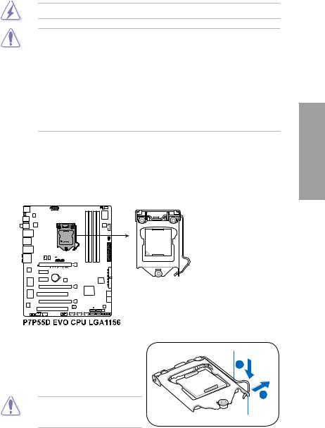
2.3.1Installing the CPU
To install a CPU:
1.Locate the CPU socket on the motherboard.
Chapter 2
2.Press the load lever with your thumb (A), and then move it to the right (B) until it is released from the retention tab.
To prevent damage to the socket pins, do not remove the PnP cap unless you are installing a CPU.
Load lever
B
Retention tab
ASUS P7P55D EVO |
2-5 |
2 Chapter
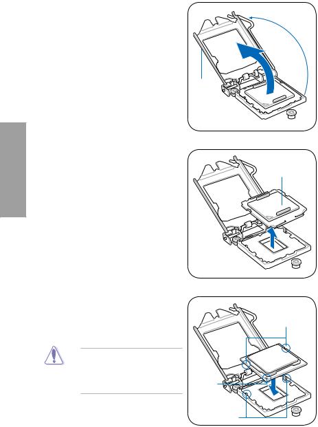
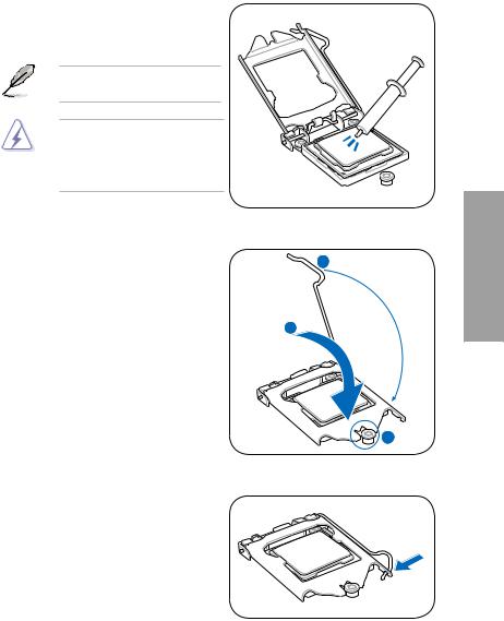
3.Lift the load lever in the direction of the arrow until the load plate is completely lifted.
4.Remove the PnP cap from the CPU socket.
5.Position the CPU over the socket, ensuring that the gold triangle is on the bottom left corner of the socket, and then fit the socket alignment keys into the CPU notches.
PnP cap
CPU notches
The CPU fits in only one correct orientation. DO NOT force the CPU into the socket to prevent bending the connectors on the socket and damaging the CPU!
Gold |
triangle |
mark |
Alignment keys |
2-6 |
Chapter 2: Hardware information |
6.Apply some Thermal Interface Material to the exposed area of the CPU that the heatsink will be in contact with, ensuring that it is spread in an even thin layer.
Some heatsinks come with pre-applied thermal paste. If so, skip this step.
The Thermal Interface Material is toxic and inedible. DO NOT eat it. If it gets into your eyes or touches your
skin, wash it off immediately, and seek professional medical help.
7. Close the load plate (A), and then push
down the load lever (B), ensuring that |
B |
|
|
the front edge of the load plate slides |
|
under the retention lock (C). |
|
|
A |
8.Insert the load lever under the retention tab.
Chapter 2
ASUS P7P55D EVO |
2-7 |
2 Chapter
2.3.2Installing the CPU heatsink and fan
The Intel® LGA1156 processor requires a specially designed heatsink and fan assembly to ensure optimum thermal condition and performance.
• When you buy a boxed Intel® processor, the package includes the CPU fan and heatsink assembly. If you buy a CPU separately, ensure that you use only Intel® certified multi directional heatsink and fan.
•Your Intel® LGA1156 heatsink and fan assembly comes in a push-pin design and does not require any tool to install.
•Use an LGA1156-compatible CPU heatsink and fan assembly only. The LGA1156 socket is incompatible with the LGA775 and LGA1366 sockets in size and dimension.
If you purchased a separate CPU heatsink and fan assembly, ensure that the Thermal Interface Material is properly applied to the CPU heatsink or CPU before you install the heatsink and fan assembly.
Ensure that you have installed the motherboard to the chassis before you install the CPU fan and heatsink assembly.
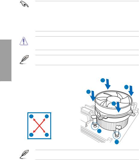
To install the CPU heatsink and fan: |
A |
|||
1. |
Place the heatsink on top of the installed |
|||
B |
||||
|
CPU, ensuring that the four fasteners |
|||
|
B |
|||
|
match the holes on the motherboard. |
|||
2. |
Push down two fasteners at a time in |
|
||
|
a diagonal sequence to secure the |
A |
||
|
heatsink and fan assembly in place. |
|||
|
|
|||
|
A |
B |
|
|
|
B |
A |
1 |
|
|
|
|||
|
|
|
1 |
|
Orient the heatsink and fan assembly such that the CPU fan cable is closest to the CPU fan connector.
2-8 |
Chapter 2: Hardware information |
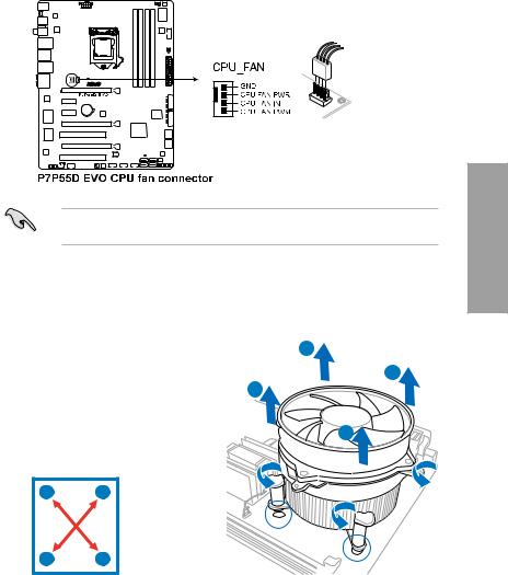
3.Connect the CPU fan cable to the connector on the motherboard labeled CPU_FAN.
DO NOT forget to connect the CPU fan connector! Hardware monitoring errors can occur if you fail to plug this connector.
2.3.3Uninstalling the CPU heatsink and fan
To uninstall the CPU heatsink and fan:
1. |
Disconnect the CPU fan cable from the |
A |
|
|
|||
|
connector on the motherboard. |
B |
|
2. |
Rotate each fastener counterclockwise. |
B |
|
3. |
Pull up two fasteners at a time in a |
|
|
|
diagonal sequence to disengage the |
A |
|
|
heatsink and fan assembly from the |
||
|
motherboard. |
|
|
|
A |
B |
|
BA
4.Carefully remove the heatsink and fan assembly from the motherboard.
Chapter 2
ASUS P7P55D EVO |
2-9 |
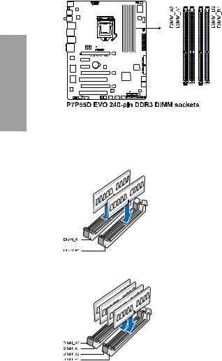
2.4System memory
2.4.1Overview
The motherboard comes with four Double Data Rate 3 (DDR3) Dual Inline Memory Modules (DIMM) sockets.
A DDR3 module has the same physical dimensions as a DDR2 DIMM but is notched differently to prevent installation on a DDR2 DIMM socket. DDR3 modules are developed for better performance with less power consumption.
The figure illustrates the location of the DDR3 DIMM sockets:
2 Chapter
Recommended memory configurations
One DIMM:
Install one memory module in slotA1 or B1 first as a single-channel operation.
Two DIMMs (dual-channel operation):
Four DIMMs (dual-channel operation):
2-10 |
Chapter 2: Hardware information |
Loading...