


P5B SE
Motherboard

E3381
Second Edition V2
September 2007
Copyright © 2007 ASUSTeK COMPUTER INC. All Rights Reserved.
No part of this manual, including the products and software described in it, may be reproduced, transmitted, transcribed, stored in a retrieval system, or translated into any language in any form or by any means, except documentation kept by the purchaser for backup purposes, without the express written permission of ASUSTeK COMPUTER INC. (“ASUS”).
Product warranty or service will not be extended if: (1) the product is repaired, modified or altered, unless such repair, modification of alteration is authorized in writing by ASUS; or (2) the serial number of the product is defaced or missing.
ASUS PROVIDES THIS MANUAL “AS IS” WITHOUT WARRANTY OF ANY KIND, EITHER EXPRESS OR IMPLIED, INCLUDING BUT NOT LIMITED TO THE IMPLIED WARRANTIES OR CONDITIONS OF MERCHANTABILITY OR FITNESS FOR A PARTICULAR PURPOSE. IN NO EVENT SHALL ASUS, ITS DIRECTORS, OFFICERS, EMPLOYEES OR AGENTS BE LIABLE FOR ANY INDIRECT, SPECIAL, INCIDENTAL, OR CONSEQUENTIAL DAMAGES (INCLUDING DAMAGES FOR LOSS OF PROFITS, LOSS OF BUSINESS, LOSS OF USE OR DATA, INTERRUPTION OF BUSINESS AND THE LIKE), EVEN IF ASUS HAS BEEN ADVISED OF THE POSSIBILITY OF SUCH DAMAGES ARISING FROM ANY DEFECT OR ERROR IN THIS MANUAL OR PRODUCT.
SPECIFICATIONS AND INFORMATION CONTAINED IN THIS MANUAL ARE FURNISHED FOR INFORMATIONAL USE ONLY, AND ARE SUBJECT TO CHANGE AT ANY TIME WITHOUT NOTICE, AND SHOULD NOT BE CONSTRUED AS A COMMITMENT BY ASUS. ASUS ASSUMES NO RESPONSIBILITY OR LIABILITY FOR ANY ERRORS OR INACCURACIES THAT MAY APPEAR IN THIS MANUAL, INCLUDING THE PRODUCTS AND SOFTWARE DESCRIBED IN IT.
Products and corporate names appearing in this manual may or may not be registered trademarks or copyrights of their respective companies, and are used only for identification or explanation and to the owners’ benefit, without intent to infringe.
ii

Contents
Notices........................................................................................................ |
vii |
Safety information..................................................................................... |
viii |
About this guide.......................................................................................... |
ix |
P5B SE specifications summary................................................................ |
xi |
Chapter 1: Product introduction
1.1 |
Welcome!....................................................................................... |
1-1 |
|
1.2 |
Package contents......................................................................... |
1-1 |
|
1.3 |
Special features............................................................................ |
1-2 |
|
|
1.3.1 |
Product highlights............................................................ |
1-2 |
|
1.3.2 |
ASUS AI Lifestyle features ............................................. |
1-3 |
|
1.3.3 |
ASUS Special features.................................................... |
1-5 |
Chapter 2: Hardware information
2.1 |
Before you proceed...................................................................... |
2-1 |
|
2.2 |
Motherboard overview................................................................. |
2-2 |
|
|
2.2.1 |
Placement direction......................................................... |
2-2 |
|
2.2.2 |
Screw holes..................................................................... |
2-2 |
|
2.2.3 |
Motherboard layout.......................................................... |
2-3 |
|
2.2.4 |
Layout contents............................................................... |
2-4 |
2.3 |
Central Processing Unit (CPU).................................................... |
2-6 |
|
|
2.3.1 |
Installing the CPU............................................................ |
2-7 |
|
2.3.2 |
Installing the heatsink and fan......................................... |
2-9 |
2.4 |
System memory.......................................................................... |
2-13 |
|
|
2.4.1 |
Overview........................................................................ |
2-13 |
|
2.4.2 |
Memory configurations.................................................. |
2-14 |
|
2.4.3 |
Installing a DIMM........................................................... |
2-18 |
|
2.4.4 |
Removing a DIMM......................................................... |
2-18 |
2.5 |
Expansion slots.......................................................................... |
2-19 |
|
|
2.5.1 |
Installing an expansion card.......................................... |
2-19 |
|
2.5.2 |
Configuring an expansion card...................................... |
2-19 |
|
2.5.3 |
Interrupt assignments.................................................... |
2-20 |
|
2.5.4 |
PCI slots........................................................................ |
2-21 |
|
2.5.5 |
PCI Express x1 slots..................................................... |
2-21 |
|
2.5.6 |
PCI Express x16 slot..................................................... |
2-21 |
iii

Contents
2.6 |
Jumpers |
....................................................................................... |
2-22 |
2.7 |
Connectors.................................................................................. |
2-24 |
|
|
2.7.1 .................................................. |
Rear panel connectors |
2-24 |
|
2.7.2 ........................................................ |
Internal connectors |
2-26 |
Chapter 3: Powering up
3.1 |
Starting up for the first time........................................................ |
3-1 |
|
3.2 |
Powering off the computer.......................................................... |
3-2 |
|
|
3.2.1 |
Using the OS shut down function.................................... |
3-2 |
|
3.2.2 |
Using the dual function power switch.............................. |
3-2 |
Chapter 4: BIOS setup
4.1 |
Managing and updating your BIOS............................................. |
4-1 |
|
|
4.1.1 |
ASUS Update utility......................................................... |
4-1 |
|
4.1.2 |
Creating a bootable floppy disk....................................... |
4-4 |
|
4.1.3 |
ASUS EZ Flash 2 utility................................................... |
4-5 |
|
4.1.4 |
AFUDOS utility................................................................ |
4-6 |
|
4.1.5 |
ASUS CrashFree BIOS 3 utility....................................... |
4-8 |
4.2 |
BIOS setup program................................................................... |
4-10 |
|
|
4.2.1 |
BIOS menu screen......................................................... |
4-11 |
|
4.2.2 |
Menu bar........................................................................ |
4-11 |
|
4.2.3 |
Navigation keys.............................................................. |
4-11 |
|
4.2.4 |
Menu items.................................................................... |
4-12 |
|
4.2.5 |
Sub-menu items............................................................ |
4-12 |
|
4.2.6 |
Configuration fields........................................................ |
4-12 |
|
4.2.7 |
Pop-up window.............................................................. |
4-12 |
|
4.2.8 |
Scroll bar....................................................................... |
4-12 |
|
4.2.9 |
General help.................................................................. |
4-12 |
4.3 |
Main menu................................................................................... |
4-13 |
|
|
4.3.1 |
System Time.................................................................. |
4-13 |
|
4.3.2 |
System Date.................................................................. |
4-13 |
|
4.3.3 |
Legacy Diskette A.......................................................... |
4-13 |
|
4.3.4 |
SATA 1, 2, 3, 4............................................................... |
4-14 |
|
4.3.5 |
IDE Configuration.......................................................... |
4-15 |
|
4.3.6 |
System Information........................................................ |
4-16 |
iv
Contents
4.4 |
Advanced menu.......................................................................... |
4-17 |
|
|
4.4.1 |
Jumperfree Configuration.............................................. |
4-17 |
|
4.4.2 |
USB Configuration......................................................... |
4-19 |
|
4.4.3 |
CPU Configuration......................................................... |
4-20 |
|
4.4.4 |
Chipset.......................................................................... |
4-21 |
|
4.4.5 |
Onboard Devices Configuration.................................... |
4-24 |
|
4.4.6 |
PCI PnP......................................................................... |
4-25 |
4.5 |
Power menu................................................................................ |
4-26 |
|
|
4.5.1 |
Suspend Mode.............................................................. |
4-26 |
|
4.5.2 |
ACPI Version Features.................................................. |
4-26 |
|
4.5.3 |
ACPI APIC Support....................................................... |
4-26 |
|
4.5.4 |
APM Configuration........................................................ |
4-27 |
|
4.5.5 |
Hardware Monitor.......................................................... |
4-28 |
4.6 |
Boot menu................................................................................... |
4-29 |
|
|
4.6.1 |
Boot Device Priority....................................................... |
4-29 |
|
4.6.2 |
Removable Drives......................................................... |
4-30 |
|
4.6.3 |
Boot Settings Configuration........................................... |
4-30 |
|
4.6.4 |
Security.......................................................................... |
4-31 |
4.7 |
Tools menu.................................................................................. |
4-33 |
|
|
4.7.1 |
ASUS EZ Flash 2.......................................................... |
4-33 |
|
4.7.2 |
ASUS O.C. Profile......................................................... |
4-34 |
4.8 |
Exit menu..................................................................................... |
4-35 |
|
Chapter 5: Software support
5.1 |
Installing an operating system.................................................... |
5-1 |
|
5.2 |
Support CD information............................................................... |
5-1 |
|
|
5.2.1 |
Running the support CD.................................................. |
5-1 |
|
5.2.2 |
Drivers menu................................................................... |
5-2 |
|
5.2.3 |
Utilities menu................................................................... |
5-3 |
|
5.2.4 |
Make Disk menu.............................................................. |
5-5 |
|
5.2.5 |
Manuals menu................................................................. |
5-5 |
|
5.2.6 |
ASUS Contact information............................................... |
5-6 |
|
5.2.7 |
Other information............................................................. |
5-7 |
5.3 |
Software information.................................................................... |
5-9 |
|
|
5.3.1 |
ASUS MyLogo™............................................................. |
5-9 |
|
5.3.2 |
Audio configurations....................................................... |
5-11 |
|
|
|
|

Contents
|
5.3.3 |
ASUS PC Probe II......................................................... |
5-15 |
5.4 |
RAID configurations................................................................... |
5-21 |
|
|
5.4.1 |
RAID definitions............................................................. |
5-21 |
|
5.4.2 |
Installing Serial ATA hard disks...................................... |
5-21 |
|
5.4.3 |
JMicron® RAID Configuration......................................... |
5-22 |
5.5 |
Creating a RAID driver disk....................................................... |
5-30 |
|
|
5.5.1 |
Creating a RAID driver disk without entering the OS.... |
5-30 |
|
5.5.2 |
Creating a RAID driver disk in Windows®...................... |
5-30 |
Appendix: CPU features
A.1 |
Intel® EM64T.................................................................................. |
A-1 |
|
A.2 |
Enhanced Intel SpeedStep® Technology (EIST)......................... |
A-1 |
|
|
A.2.1 |
System requirements....................................................... |
A-1 |
|
A.2.2 |
Using the EIST................................................................. |
A-2 |
A.3 |
Intel® Hyper-Threading Technology............................................ |
A-3 |
|
vi

Notices
Federal Communications Commission Statement
This device complies with Part 15 of the FCC Rules. Operation is subject to the following two conditions:
•This device may not cause harmful interference, and
•This device must accept any interference received including interference that may cause undesired operation.
This equipment has been tested and found to comply with the limits for a Class B digital device, pursuant to Part 15 of the FCC Rules. These limits are designed to provide reasonable protection against harmful interference in a residential installation. This equipment generates, uses and can radiate radio
frequency energy and, if not installed and used in accordance with manufacturer’s instructions, may cause harmful interference to radio communications. However, there is no guarantee that interference will not occur in a particular installation. If this equipment does cause harmful interference to radio or television reception, which can be determined by turning the equipment off and on, the user is encouraged to try to correct the interference by one or more of the following measures:
•Reorient or relocate the receiving antenna.
•Increase the separation between the equipment and receiver.
•Connect the equipment to an outlet on a circuit different from that to which the receiver is connected.
•Consult the dealer or an experienced radio/TV technician for help.
The use of shielded cables for connection of the monitor to the graphics card is required to assure compliance with FCC regulations. Changes or modifications to this unit not expressly approved by the party responsible for compliance could void the user’s authority to operate this equipment.
Canadian Department of Communications Statement
This digital apparatus does not exceed the Class B limits for radio noise emissions from digital apparatus set out in the Radio Interference Regulations of the Canadian Department of Communications.
This class B digital apparatus complies with Canadian ICES-003.
vii
Safety information
Electrical safety
•To prevent electrical shock hazard, disconnect the power cable from the electrical outlet before relocating the system.
•When adding or removing devices to or from the system, ensure that the power cables for the devices are unplugged before the signal cables are connected. If possible, disconnect all power cables from the existing system before you add a device.
•Before connecting or removing signal cables from the motherboard, ensure that all power cables are unplugged.
•Seek professional assistance before using an adpater or extension cord. These devices could interrupt the grounding circuit.
•Make sure that your power supply is set to the correct voltage in your area. If you are not sure about the voltage of the electrical outlet you are using, contact your local power company.
•If the power supply is broken, do not try to fix it by yourself. Contact a qualified service technician or your retailer.
Operation safety
•Before installing the motherboard and adding devices on it, carefully read all the manuals that came with the package.
•Before using the product, make sure all cables are correctly connected and the power cables are not damaged. If you detect any damage, contact your dealer immediately.
•To avoid short circuits, keep paper clips, screws, and staples away from connectors, slots, sockets and circuitry.
•Avoid dust, humidity, and temperature extremes. Do not place the product in any area where it may become wet.
•Place the product on a stable surface.
•If you encounter technical problems with the product, contact a qualified service technician or your retailer.
This symbol of the crossed out wheeled bin indicates that the product (electrical, electronic equipment and mercury-containing button cell battery) should not
be placed in municipal waste. Check local regulations for disposal of electronic products.
viii

About this guide
This user guide contains the information you need when installing and configuring the motherboard.
How this guide is organized
This guide contains the following parts:
•Chapter 1: Product introduction
This chapter describes the features of the motherboard and the new technology it supports.
•Chapter 2: Hardware information
This chapter lists the hardware setup procedures that you have to perform when installing system components. It includes description of the switches, jumpers, and connectors on the motherboard.
•Chapter 3: Powering up
This chapter describes the power up sequence and ways of shutting down the system.
•Chapter 4: BIOS setup
This chapter tells how to change system settings through the BIOS Setup menus. Detailed descriptions of the BIOS parameters are also provided.
•Chapter 5: Software support
This chapter describes the contents of the support CD that comes with the motherboard package.
•Appendix: CPU features
The Appendix describes the CPU features and technologies that the motherboard supports.
Where to find more information
Refer to the following sources for additional information and for product and software updates.
1.ASUS websites
The ASUS website provides updated information on ASUS hardware and software products. Refer to the ASUS contact information.
2.Optional documentation
Your product package may include optional documentation, such as warranty flyers, that may have been added by your dealer. These documents are not part of the standard package.
ix

Conventions used in this guide
To make sure that you perform certain tasks properly, take note of the following symbols used throughout this manual.
DANGER/WARNING: Information to prevent injury to yourself when trying to complete a task.
CAUTION: Information to prevent damage to the components when trying to complete a task.
IMPORTANT: Instructions that you MUST follow to complete a task.
NOTE: Tips and additional information to help you complete a task.
Typography
Bold text |
Indicates a menu or an item to select. |
Italics |
Used to emphasize a word or a phrase. |
<Key> |
Keys enclosed in the less-than and greater-than sign |
|
means that you must press the enclosed key. |
|
Example: <Enter> means that you must press the |
|
Enter or Return key. |
<Key1>+<Key2>+<Key3> If you must press two or more keys simultaneously, the key names are connected with a plus sign (+).
|
Example: <Ctrl>+<Alt>+<D> |
Command |
Means that you must type the command exactly as |
|
shown. |
|
Example: At the DOS prompt, type the command line: |
|
afudos /i[filename] |
|
afudos /iP5BSE.ROM |
P5B SE specifications summary
CPU
Chipset
System bus
Memory
Expansion slots
Storage
LAN
High DefinitionAudio
USB
ASUS special features
ASUS Exclusive Overclocking features
LGA775 socket for Intel® Core™2 Quad/Core™2 Extreme/ Core™2 Duo/ Pentium® Extreme/ Pentium® D/ Pentium® 4 processors
Compatible with Intel® 05B/05A and 06 processors Supports Intel® next generation 45nm Multi-Core CPU * Refer to www.asus.com for Intel® CPU support list
Northbridge: Intel® P965 with Intel® Fast Memory Access Southbridge: Intel® ICH8
1333*(overclocking)/1066/800/533 MHz
*The chipset officially supports the FSB up to 1066MHz. Tuned by the ASUS exclusive technology, this motherboard supports up to FSB 1333MHz. Refer to www.asus.com for Intel® CPU support list
Dual-channel memory architecture
-4 x 240-pin DIMM sockets support unbuffered non-ECC DDR2 800/667/533 MHz memory modules
-Supports up to 8 GB system memory
1 x PCI Express™ x16 slot
2 x PCI Express™ x1 slots
3 x PCI slots
Intel® ICH8 supports:
- 4 x SATA 3 Gb/s connectors
JMicron® JMB363 PATA and SATA controller supports:
-1 x UltraDMA 133/100/66 for up to 2 PATA devices
-1 x Internal SATA 3 Gb/s
-1 x External SATA 3 Gb/s port on the rear panel
-RAID 0, RAID 1, and JBOD configuration
(by 1 x External Serial ATA and 1 x Internal Serial ATA)
PCIe Gigabit LAN controller
Realtek® ALC662 6-channel CODEC
Supports up to 10 USB 2.0/1.1 ports (six at mid-board, four on the rear panel)
ASUS Q-Fan
ASUS Q-Connector
ASUS O.C. Profile
ASUS CrashFree BIOS 3
ASUS EZ Flash 2
MyLogo
Stepless Frequency Selection (SFS) allows
-FSB tuning from 100MHz up to 500MHz at 1MHz increment;
Overclocking protection:
- ASUS C.P.R. (CPU Parameter Recall)
(continued on the next page)
xi
P5B SE specifications summary
Rear panel
Internal connectors
BIOS features
Manageability
Support CD contents
Form factor
1 x PS/2 keyboard port
1 x PS/2 mouse port
1 x Parallel port
1 x Serial port
1 x External Serial ATA port
1 x LAN (RJ-45) port
4 x USB 2.0/1.1 ports
6-channel audio ports
3 x USB 2.0 connectors support six additional USB 2.0 ports 1 x Floppy disk drive connector
1 x IDE connector for two devices
5 x Serial ATA connectors
1 x CPU / 1 x Chassis / 1 x Power fan connectors 1 x S/PDIF Out connector
Chassis intrusion connector Front panel audio connector CD audio in connector 24-pin ATX power connector
4-pin ATX 12 V power connector System panel connector
8 Mb Flash ROM, AMI BIOS, PnP, DMI 2.0, WfM2.0, SM BIOS 2.5, ACPI v3.0, ASUS EZ Flash 2, ASUS CrashFree BIOS 3
WOL by PME, WOR by PME, PXE
Device drivers
ASUS PC Probe II
ASUS Update
Anti-virus software (OEM version)
ATX form factor: 12 in x 7.4 in (30.5 cm x 18.8 cm)
*Specifications are subject to change without notice.
xii
This chapter describes the motherboard features and the new technologies
it supports.
Product1 introduction

|
Chapter summary |
1 |
|
|
|
||
|
|
|
|
|
|
|
|
1.1 |
Welcome!....................................................................................... |
1-1 |
1.2 |
Package contents......................................................................... |
1-1 |
1.3 |
Special features............................................................................ |
1-2 |
ASUS P5B SE
1.1Welcome!
Thank you for buying an ASUS® P5B SE motherboard!
The motherboard delivers a host of new features and latest technologies, making it another standout in the long line of ASUS quality motherboards!
Before you start installing the motherboard, and hardware devices on it, check the items in your package with the list below.
1.2Package contents
Check your motherboard package for the following items.
Motherboard |
ASUS P5B SE |
|
|
|
|
Cables |
1 x Serial ATA power cable |
|
|
|
2 x Serial ATA signal cables |
|
|
1 x Ultra DMA 133/100/66 cable |
|
|
1 x Floppy disk drive cable |
|
|
|
Accessories |
I/O shield |
|
|
|
1 x ASUS Q-connector kit (USB, system panel; Retail |
|
|
version only) |
|
|
|
Application CD |
ASUS motherboard support CD |
|
|
|
ASUS Superb Software Library CD |
|
|
|
Documentation |
User guide |
|
|
|
|
|
|
|
If any of the above items is damaged or missing, contact your retailer.
ASUS P5B SE |
1- |

1.3Special features
1.3.1Product highlights
Green ASUS
This motherboard and its packaging comply with the European Union’s Restriction on the use of Hazardous Substances (RoHS). This is in line with the ASUS vision of creating environment-friendly and recyclable products/packaging to safeguard consumers’ health while minimizing the impact on the environment.
LGA775 Intel® Quad-core Processor Ready 
This motherboard supports the latest powerful and energy efficient processors from Intel. Intel® Quad-core is based on the Intel Core Microarchitecture process technology that allows users to step up to new levels of gaming experience and multi-tasking performance.
Combined with 1066/800 of front side bus (FSB), this motherboard guarantees enhanced user experience in the digital home and office.
LGA775 Intel® Core™2 Processor Ready 
This motherboard supports the latest Intel® Core™2 processor in the LGA775 package. With the new Intel® Core™ microarchitecture technology and 1333(O.C)/1066 / 800 MHz FSB, Intel® Core™2 processor is one of the most powerful and energy efficient CPU in the world.
Intel P965 Chipset 
The Intel® P965 Express Chipset is the latest chipset designed to support 8GB of dual-channel DDR2 800/667/533 architecture, 1333(O.C)/1066/800/533 FSB (Front Side Bus), PCI Express x16 graphics and multi-core CPU. It especially includes the Intel® Fast Memory Access technology that significantly optimizes the use of available memory bandwidth and reduces the latency of the memory accesses.
DDR2 memory support 


The motherboard supports DDR2 memory that features data transfer rates of 800/667/533 MHz to meet the higher bandwidth requirements of the latest 3D graphics, multimedia, and Internet applications. The dual-channel DDR2 architecture doubles the bandwidth of your system memory to boost system
performance, eliminating bottlenecks with peak bandwidths of up to 12.8 GB/s. Without restriction to the memory size across the two channels, the motherboard allows you to install DIMMs with different memory size and enjoy dual-channel feature at the same time. See pages 213 to 2-17 for details.
1- |
Chapter 1: Product introduction |

Serial ATA 3 Gb/s technology and SATA on the go 


This motherboard supports the next-generation hard drives based on the Serial ATA (SATA) 3Gb/s storage specification, delivering enhanced scalability and doubling the bus bandwidth for high-speed data retrieval and saves. The external SATA port located at the back I/O provides smart setup and hot-plug functions. Easily backup photos, videos and other entertainment contents to external devices. See pages 2-25, 2-27, and 2-28 for details.
S/PDIF digital sound ready 
This motherboard provides convenient connectivity to external home theater audio systems via coaxial and optical S/PDIF-out (SONY-PHILIPS Digital Interface) jack. It allows to transfer digital audio without converting to analog format and keeps the best signal quality. See page 2-28 for details.
High DefinitionAudio 
Enjoy high-end sound quality on your PC! The onboard 6-channel HD audio (High Definition Audio, previously codenamed Azalia) CODEC enables high-quality 192 KHz/ 24-bit audio output and jack-sensing feature! With CODEC, 6-channel audio ports, and S/PDIF interfaces, you can connect your computer to home theater decoders to produce crystal-clear digital audio. See pages 2-24 and 4-23 for details.
1.3.2ASUS Special features
ASUS Q-Fan technology 
The ASUS Q-Fan technology smartly adjusts the CPU fan speed according to the system loading to ensure quiet, cool, and efficient operation. See pages 2-30 and 4-28 for details.
ASUS O.C. Profile 
The motherboard features the ASUS O.C. Profile that allows users to conveniently store or load multiple BIOS settings. The BIOS settings can be stored in the CMOS or a separate file, giving users freedom to share and distribute their favorite settings. See page 4-34 for details.
ASUS CrashFree BIOS 3 
The ASUS CrashFree BIOS 3 allows users to restore corrupted BIOS data from a USB flash disk containing the BIOS file. See page 4-8 for details.
ASUS P5B SE |
1- |

ASUS Q-Connector
ASUS Q-Connector allows you to easily connect or disconnect the chassis front panel cables to the motherboard. This unique module eliminates the trouble of connecting the system panel cables one at a time and avoiding wrong cable connections. See page 2-34 for details.
ASUS EZ Flash 2 
EZ Flash 2 is a user-friendly BIOS update utility. Simply press the predefined hotkey to launch the utility and update the BIOS without entering the OS. Update your BIOS easily without preparing a bootable diskette or using an OS-based flash utility. See pages 4-5 and 4-33 for details.
ASUS MyLogo™ 
ASUS My Logo is the new feature present in the motherboard that allows you to personalize and add style to your system with customizable boot logos. See page 5-9 for details.
C.P.R. (CPU Parameter Recall) 
The C.P.R. feature of the motherboard BIOS allows automatic re-setting to the BIOS default settings in case the system hangs due to overclocking. When the system hangs due to overclocking, C.P.R. eliminates the need to open the system chassis and clear the RTC data. Simply shut down and reboot the system, and the BIOS automatically restores the CPU default setting for each parameter. See page 2-22 for details.
1- |
Chapter 1: Product introduction |
This chapter lists the hardware setup procedures that you have to perform when installing system components. It includes description of the jumpers and connectors on the motherboard.
Hardware2 information

|
Chapter summary |
2 |
|
|
|
||
|
|
|
|
|
|
|
|
2.1 |
Before you proceed...................................................................... |
2-1 |
2.2 |
Motherboard overview................................................................. |
2-2 |
2.3 |
Central Processing Unit (CPU).................................................... |
2-6 |
2.4 |
System memory.......................................................................... |
2-13 |
2.5 |
Expansion slots.......................................................................... |
2-19 |
2.6 |
Jumpers....................................................................................... |
2-22 |
2.7 |
Connectors.................................................................................. |
2-24 |
ASUS P5B SE
2.1Before you proceed
Take note of the following precautions before you install motherboard components or change any motherboard settings.
•Unplug the power cord from the wall socket before touching any component.
•Use a grounded wrist strap or touch a safely grounded object or a metal object, such as the power supply case, before handling components to avoid damaging them due to static electricity.
•Hold components by the edges to avoid touching the ICs on them.
•Whenever you uninstall any component, place it on a grounded antistatic pad or in the bag that came with the component.
•Before you install or remove any component, ensure
that the ATX power supply is switched off or the power cord is detached from the power supply. Failure to do so may cause severe damage to the motherboard, peripherals, and/or components.
Onboard LED
The motherboard comes with a standby power LED that lights up to indicate that the system is ON, in sleep mode, or in soft-off mode. This is a reminder that you should shut down the system and unplug the power cable before removing or plugging in any motherboard component. The illustration below shows the location of the onboard LED.
P5B SE
SB_PWR
|
ON |
OFF |
|
Standby |
Powered |
P5B SE Onboard LED |
Power |
Off |
|
|
ASUS P5B SE |
2- |
2.2Motherboard overview
Before you install the motherboard, study the configuration of your chassis to ensure that the motherboard fits into it.
Make sure to unplug the power cord before installing or removing the motherboard. Failure to do so can cause you physical injury and damage motherboard components.
2.2.1Placement direction
When installing the motherboard, make sure that you place it into the chassis in the correct orientation. The edge with external ports goes to the rear part of the chassis as indicated in the image below.
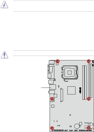
2.2.2Screw holes
Place six (6) screws into the holes indicated by circles to secure the motherboard to the chassis.
Do not overtighten the screws! Doing so can damage the motherboard.
Place this side towards the rear of the chassis
®
P5B SE
|
|
|
|
|
|
|
|
|
|
|
|
|
|
|
|
|
|
|
|
|
|
|
|
|
|
|
|
|
|
|
|
|
|
|
|
|
|
|
|
|
|
|
|
|
|
|
|
|
|
|
|
|
|
|
|
|
|
|
|
|
|
|
|
|
|
|
|
|
|
|
|
|
|
|
|
|
|
|
|
|
|
|
|
|
|
|
|
|
|
|
|
|
|
|
|
|
|
|
|
|
|
|
|
|
|
|
|
|
|
|
|
|
|
|
|
|
|
|
|
|
|
|
|
|
|
|
|
|
|
|
|
|
|
|
|
|
|
|
|
|
|
|
|
|
|
|
|
|
|
|
|
|
|
|
|
|
|
|
|
|
|
|
|
|
|
|
|
|
|
|
|
|
|
|
|
|
|
|
|
|
|
|
|
|
|
|
|
|
|
|
|
|
|
|
|
|
|
|
|
|
|
|
|
|
|
|
|
|
|
|
|
|
|
|
|
|
|
|
|
|
|
|
|
|
|
|
|
|
|
|
|
|
|
|
|
|
|
|
|
|
|
|
|
|
|
|
|
|
|
|
|
|
|
|
|
|
|
|
|
|
|
|
|
|
|
|
|
|
|
|
|
|
|
|
|
|
|
|
|
|
|
|
|
|
|
|
|
|
|
|
|
|
|
|
|
|
|
|
|
|
|
|
|
|
|
|
|
|
|
|
|
|
|
|
|
|
|
|
|
|
|
|
|
|
|
|
|
|
|
|
|
|
|
|
|
|
|
|
|
|
|
|
|
|
|
|
|
|
|
|
|
|
|
|
|
|
|
|
|
|
|
|
|
|
|
|
|
|
|
|
|
|
|
|
|
|
|
|
|
|
|
|
|
|
|
|
|
|
|
|
|
|
|
|
|
|
|
|
|
|
|
|
|
|
|
|
|
|
|
|
|
|
|
|
|
|
|
|
|
|
|
|
|
|
|
|
|
|
|
|
|
|
|
|
|
|
|
|
|
|
|
|
|
|
|
|
|
|
|
|
|
|
|
|
|
|
|
|
|
|
|
|
|
|
|
|
|
2- |
|
|
|
|
Chapter 2: Hardware information |
||||||||||||||||||||

2.2.3Motherboard layout
18.8cm (7.4in)
PS/2KBMS |
KBPWR |
|
||
T: Mouse |
|
|
|
|
B: Keyboard |
|
|
|
|
COM1 |
ATX12V |
|
|
|
|
PARALLEL PORT |
|
|
LGA775 |
ESATA |
|
|
|
|
USB34 |
CHA_FAN |
|
|
|
LAN1_USB12 |
USBPW1-4 |
|
||
|
|
|
|
|
|
|
|
|
Intel® |
Top:Line In |
|
|
P965 |
|
Center:Line Out |
EATXPWR |
|
||
Below:Mic In |
|
|
||
|
|
LAN |
|
|
|
AAFP |
CD |
|
P5B SE |
PCIEX16_1
ALC662
PCIEX1_1
|
|
|
CPU_FAN |
|
|
|
|
|
(64 bit,240-pin module) |
(64 bit,240-pin module) |
PWR FAN |
|
bit,240-pin module) |
bit,240-pin module) |
|
||
® |
DDR2 DIMM A1 (64 |
DDR2 DIMM A2 (64 |
DDR2 DIMM B1 |
DDR2 DIMM B2 |
(12.0in) |
|
|
|
|
|
30.5cm |
|
Super I/O |
|
|
|
|
|
|
|
|
|
|
|
|
|
|
|
PCI1 |
|
|
|
|
|
|
|
|||||||||||
|
|
|
|
|
|
|
|
|
|
|
|
|
|
|
|
|
|
|
SB_PWR |
|
|
|
|
||||||||||||
|
|
|
|
|
|
|
|
|
|
|
|
|
|
|
|
|
|
|
|
|
|
|
|
|
|
|
|
|
|
|
|
|
|
|
|
|
|
|
|
|
|
|
|
|
|
|
|
|
|
|
|
|
|
|
|
|
|
|
PCI2 |
|
|
|
|
|
|
|
|||||
|
|
|
|
SATA_E1 |
|
|
|
|
|
|
|
|
|
|
|
|
|
|
|||||||||||||||||
|
|
|
|
|
|
|
|
|
|
|
|
|
|
|
|
|
|
|
|
|
|
|
|
||||||||||||
|
|
|
|
|
|
|
|
|
|
|
|
|
|
|
|
|
|
|
|
|
|
|
|
|
|
|
|
|
|
|
|
|
|
|
|
JMB363 |
|
|
|
|
|
|
|
|
|
|
|
|
|
|
|
|
PCI3 |
|
|
|
|
|
BIOS |
||||||||||||
|
|
|
|
|
|
|
|
|
|
|
|
|
|
|
|
|
USBPW9-10 |
|
|
|
|
|
|||||||||||||
|
|
|
|
|
|
|
|
|
|
|
|
|
|
|
|
|
|
|
|
|
|
|
|
||||||||||||
|
|
|
|
|
|
|
|
|
|
|
|
|
|
|
|
|
|
|
|
|
|
|
|
USBPW5-8 |
|
|
|
|
|
|
|
||||
|
|
|
|
|
|
|
|
|
|
|
|
|
|
|
|
|
|
|
SPDIF_OUT |
|
CR2032 3V |
|
|
||||||||||||
|
|
|
|
|
|
|
|
|
|
|
|
|
|
|
|
|
|
|
|
|
|
|
|
|
|
|
|
|
Lithium Cell |
|
|
||||
|
|
|
|
|
|
|
|
|
|
|
|
|
|
|
|
|
|
PCIEX1_2 |
|
|
|
|
|
|
|
|
CMOS Power |
|
|
||||||
|
|
|
|
|
|
|
|
|
|
|
|
|
|
|
|
|
|
|
|
|
|
|
|
|
|
|
|
|
|
|
|
|
|||
|
FLOPPY |
|
|
|
|
USB910 |
|
|
USB56 |
USB78 |
PRI_EIDE |
||||||||||||||||||||||||
|
|
|
|
|
|
|
|
|
|
|
|
|
|
|
|
|
|
|
|
|
|
|
|
|
|
|
|
|
|
|
|
|
|
|
|
Intel®
ICH8
SATA4 |
|
SATA3 |
|
SATA2 |
|
SATA1 |
PANEL |
CHASSIS
CLRTC 
Refer to 2.7 Connectors for more information about rear panel connectors and internal connectors.
ASUS P5B SE |
2- |
2.2.4Layout contents
Slots |
|
Page |
1. |
DDR2 DIMM slots |
2-13 |
2. |
PCI slots |
2-21 |
3. |
PCI Express x1 slots |
2-21 |
4. |
PCI Express x16 slot |
2-21 |
Jumpers |
|
Page |
1. |
Clear RTC RAM (3-pin CLRTC) |
2-22 |
|
|
|
2. |
USB Device wake-up (3-pin USBPW1-4, USBPW5-8, |
2-23 |
|
USBPW910) |
|
|
|
|
3. |
Keyboard power (3-pin KBPWR) |
2-23 |
|
|
|
Rear panel connectors |
Page |
|
1. |
PS/2 keyboard port (purple) |
2-24 |
2. |
Parallel port |
2-24 |
3. |
LAN (RJ-45) port |
2-24 |
4. |
Line In port (light blue) |
2-24 |
5. |
Line Out port (lime) |
2-24 |
6. |
Microphone port (pink) |
2-24 |
7. |
USB 2.0 ports 1 and 2 |
2-24 |
8. |
USB 2.0 ports 3 and 4 |
2-24 |
9. |
External SATA ports |
2-25 |
10. |
Serial port |
2-25 |
11. |
PS/2 keyboard port (purple) |
2-25 |
2- |
Chapter 2: Hardware information |

Internal connectors |
Page |
|
1. |
Floppy disk drive connector (34-1 pin FLOPPY) |
2-26 |
2. |
IDE connector (40-1 pin PRI_EIDE) |
2-26 |
3. |
ICH8 Serial ATA connectors (7-pin SATA1, SATA2,SATA3, |
2-27 |
|
SATA4) |
|
4. |
JMicron® JMB363 Serial ATA RAID connector |
2-28 |
|
(7-pin SATA_RAID) |
|
5. |
Digital audio connector (4-1 pin SPDIF_OUT) |
2-28 |
6. |
USB connectors (10-1 pin USB56, USB 78, USB910) |
2-29 |
7. |
Optical drive audio connector (4-pin CD) |
2-29 |
8. |
CPU, chassis, and power fan connectors (4-pin CPU_FAN, |
2-30 |
|
3-pin CHA_FAN, 3-pin PWR_FAN) |
|
9. |
Chassis intrusion connector (4-1 pin CHASSIS) |
2-30 |
10. |
Front panel audio connector (10-1 pin AAFP) |
2-31 |
|
|
|
11. |
ATX power connectors (24-pin EATXPWR, 4-pin ATX12V) |
2-32 |
|
|
|
12. |
System panel connector (20-8 pin PANEL) |
2-33 |
|
|
|
|
ASUS Q-Connector (system panel) |
2-34 |
|
|
|
ASUS P5B SE |
2- |
2.3Central Processing Unit (CPU)
The motherboard comes with a surface mount LGA775 socket designed for the Intel® Core™2 Quad/Core™2 Extreme/ Core™2 Duo/ Pentium® Extreme/ Pentium® D/ Pentium® 4 processors
•Make sure the AC power is off before you install the CPU.
•If installing a dual-core CPU, connect the chassis fan cable to the CHA_FAN connector to ensure system stability.
•Upon purchase of the motherboard, make sure that the PnP cap is on the socket and the socket contacts are not bent. Contact your retailer
immediately if the PnP cap is missing, or if you see any damage to the PnP cap/socket contacts/motherboard components. ASUS will shoulder the cost of repair only if the damage is shipment/transit-related.
•Keep the cap after installing the motherboard. ASUS will process Return Merchandise Authorization (RMA) requests only if the motherboard comes with the cap on the LGA775 socket.
•The product warranty does not cover damage to the socket contacts resulting from incorrect CPU installation/removal, or misplacement/loss/ incorrect removal of the PnP cap.
2- |
Chapter 2: Hardware information |
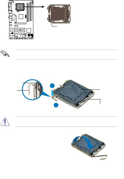
2.3.1Installing the CPU
To install a CPU:
1.Locate the CPU socket on the motherboard.
P5B SE
P5B SE CPU Socket 775
Before installing the CPU, make sure that the cam box is facing towards you and the load lever is on your left.
2.Press the load lever with your thumb (A), then move it to the left (B) until it is released from the retention tab.
Retention tab |
A |
|
|
Load lever |
PnP cap |
BThis side of the socket box should face you.
To prevent damage to the socket pins, do not remove the PnP cap unless you are installing a CPU.
3.Lift the load lever in the direction of the arrow to a 135º angle.
ASUS P5B SE |
2- |
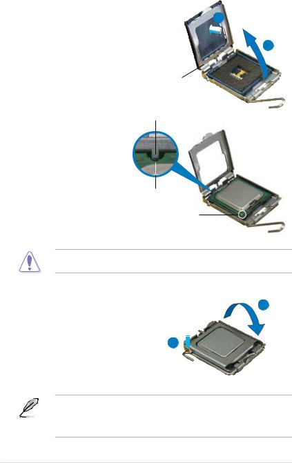
4.Lift the load plate with your thumb and forefinger to a 100º angle (A), then push the PnP cap from the load plate window to remove (B).
B
Load plate
Alignment key
5.Position the CPU over the socket, making sure that the gold triangle is on the bottom left corner of the socket then fit the socket alignment key into the CPU notch.
CPU notch
Gold triangle mark
The CPU fits in only one correct orientation. DO NOT force the CPU into the socket to prevent bending the connectors on the socket and damaging the CPU!
6. |
Close the load plate (A), then |
A |
|
push the load lever (B) until it |
|
|
snaps into the retention tab. |
|
7. |
If installing a dual-core CPU, |
|
connect the chassis fan cable to the CHA_FAN1 connector to ensure system stability.
B
The motherboard supports Intel® LGA775 processors with the Intel® Enhanced Memory 64 Technology (EM64T), Enhanced Intel SpeedStep® Technology (EIST), and Hyper-Threading Technology. Refer to the Appendix for more information on these CPU features.
2- |
Chapter 2: Hardware information |
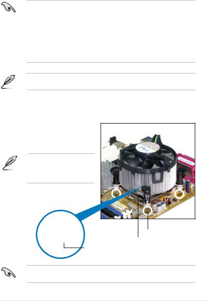
2.3.2Installing the CPU heatsink and fan
The Intel® LGA775 processor requires a specially designed heatsink and fan assembly to ensure optimum thermal condition and performance.
•When you buy a boxed Intel® processor, the package includes the CPU fan
and heatsink assembly. If you buy a CPU separately, make sure that you use only Intel® certified multi directional heatsink and fan.
•Your Intel® LGA775 heatsink and fan assembly comes in a push-pin design and requires no tool to install.
•If you purchased a separate CPU heatsink and fan assembly, make sure that you have properly applied Thermal Interface Material to the CPU heatsink or CPU before you install the heatsink and fan assembly.
Make sure that you have installed the motherboard to the chassis before you install the CPU fan and heatsink assembly.
To install the CPU heatsink and fan:
1.Place the heatsink on top of the installed CPU, making sure that the four fasteners match the holes on the motherboard.
Orient the heatsink and fan assembly such that the CPU fan cable is closest to the CPU fan connector.
Motherboard hole
Fastener
Narrow end of the groove
Make sure to orient each fastener with the narrow end of the groove pointing outward. (The photo shows the groove shaded for emphasis.)
ASUS P5B SE |
2- |
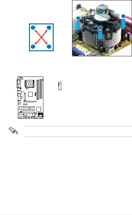
2.Push down two fasteners at a time in a diagonal sequence to secure the
heatsink and fan assembly in place. |
|
B |
|
|
|
A |
A |
|
|
|
|
A |
B |
|
B |
BA
3.Connect the CPU fan cable to the connector on the motherboard labeled CPU_FAN.

 CPU_FAN
 GND
GND
 CPU FAN PWR
 CPU FAN IN
 CPU FAN PWM
A
P5B SE
P5B SE CPU fan connector
Do not forget to connect the CPU fan connector! Hardware monitoring errors can occur if you fail to plug this connector.
2-10 |
Chapter 2: Hardware information |
 Loading...