


 Loading...
K Service Source
iMac (Summer 2001)
Note: The procedures for this product are almost identical to the iMac (Early 2001) computer. To differentiate the two models, refer to the individual Service Source chapters, the Knowledge Base, or the Technical Information Library.
© 2001 Apple Computer, Inc. All rights reserved.

K Service Source
Take Apart
iMac (Summer 2001)
Note: The parenthetical product description (Summer 2001) refers to the summer of the Northern Hemisphere.
Take Apart |
- 1 |
|
|
|
|
What’s New
New Models
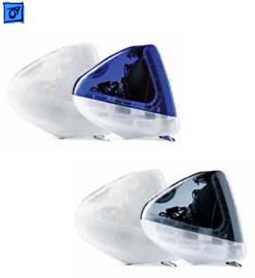
There are four models of the iMac: the 500 MHz iMac in Indigo (Education only), the 500 MHz in Indigo and Snow, the 600 MHz iMac in Graphite and Snow, and the 700 MHz iMac Special Edition in Graphite and Snow.
Note: The 500 MHz Education iMac uses logic board 661-2447.

Take Apart |
- 2 |
|
|
|
|
Part Changes for iMac (Summer 2001)
•Logic boards:
–added 661-2548, 700 MHz board
–661-2447, 500 MHz board is now used in educational iMacs, previously it was an international board only
•Hard drives:
–added 661-2521, 60 GB Hard Drive
•External plastics
–added 922-4609, Front Outer Bezel, Snow, Rev. 2

Take Apart |
- 3 |
|
|
|
|
The following take apart procedures for the iMac (Summer 2001) computers are identical to take apart procedures for iMac (Early 2001) and iMac (Summer 2000) computers.
The Indigo Mac (Summer 2000) was used for all the pictures in this chapter.

Take Apart |
- 4 |
|
|
|
|
Tools
The following tools are recommended for the take apart procedures:
• phillips screwdriver (No.1 and No.2)
• a stubby (short) phillips screwdriver
• plastic flatblade screwdriver to release tabs on plastic housing
• jeweler’s screwdriver
• CRT discharge tool
• needlenose pliers
• ESD mat
Take Apart |
Bottom Housing With Flip Foot - 5 |
|
|
|
|
Procedures
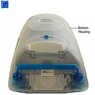
Bottom Housing With
Flip Foot
Before you begin, position the computer face down, resting the computer on an ESD mat or other soft surface.
Take Apart |
Bottom Housing With Flip Foot - 6 |
|
|
|
|
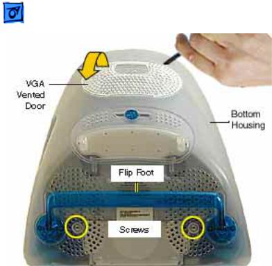
1. Using a plastic flatblade screwdriver, remove the VGA vented cover.
2. Remove the two screws near the flip foot.

Take Apart |
Bottom Housing With Flip Foot - 7 |
|
|
|
|
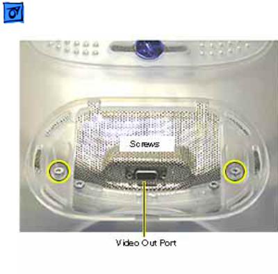
3. Remove the video out access door from the bottom housing.
Take Apart |
Bottom Housing With Flip Foot - 8 |
|
|
|
|
4. Remove the two outer screws located near the video out port.
Replacement Note: The bottom housing uses two sizes of screws. The two shorter screws attach near the flip foot.
Take Apart |
Bottom Housing With Flip Foot - 9 |
|
|
|
|
5. Pull the bottom housing off the computer.
Take Apart |
Bottom Housing With Flip Foot - 10 |
|
|
|
|
Bottom Housing
Replacement Note
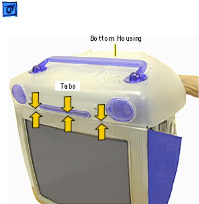
1. Align the three tabs on the bottom housing with the tab slots on the front outer bezel.
Ensure that the center tab is properly aligned or CDs and DVD discs may not eject from the slot.
2. Lower the bottom housing into place and replace the screws.
Take Apart |
EMI Cover - 11 |
|
|
|
|
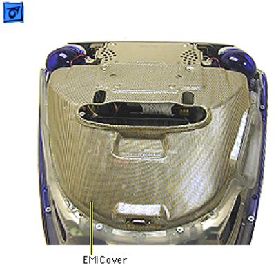
EMI Cover
Before you begin:
• Position the computer upside down, resting the computer on an ESD mat or other soft surface.
• Remove the bottom housing.
Take Apart |
EMI Cover - 12 |
|
|
|
|
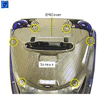
1. Remove the six screws on the EMI cover.
Take Apart |
EMI Cover - 13 |
|
|
|
|
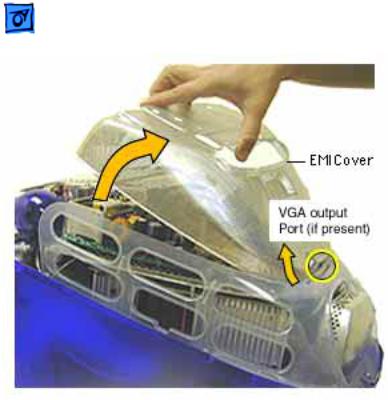
2. Lift the EMI cover off the computer.
Note: Be careful of the
VGA output port.

Take Apart |
EMI Cover - 14 |
|
|
|
|
Replacement Note: Position the rear of the EMI cover into place first, positioning the EMI cover over the video port (if present). Continue lowering the cover into place by gently squeezing in on both sides, as you lower the cover into position.

Take Apart |
SDRAM DIMM - 15 |
|
|
|
|
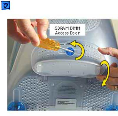
SDRAM DIMM
Before you begin, position the computer face down, resting the CRT on an ESD mat or other soft surface.
Take Apart |
SDRAM DIMM - 16 |
|
|
|
|
1. With a flatblade screwdriver or coin, turn the colored latch counterclockwise on the access door.
2. Pull the access door down to open.

Take Apart |
SDRAM DIMM - 17 |
|
|
|
|
3. Push down on the plastic tabs to release the SDRAM module(s).
4. Carefully lift the SDRAM from the slot.
Note: Remove installed SDRAM from the logic board before returning the logic board to Apple.
Take Apart |
AirPort Card - 18 |
|
|
|
|
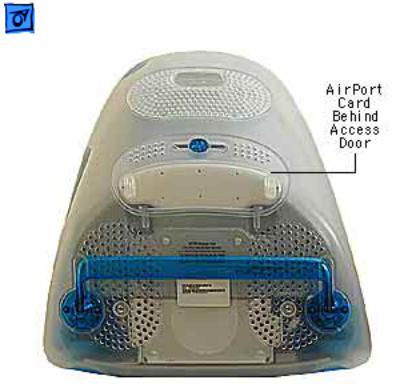
AirPort Card
Before you begin, position the computer face down, resting the CRT on an ESD mat or other soft surface.
Note: If the AirPort Card is not installed, a protective antenna cap will be attached to the antenna.
Take Apart |
AirPort Card - 19 |
|
|
|
|
1. With a flatblade screwdriver or coin, turn the colored latch to open the access door.
The antenna and AirPort Card will be visible when you open the access door.
Note: If the AirPort card is not installed, a clear protective antenna cap will be attached to the antenna.
Take Apart |
AirPort Card - 20 |
|
|
|
|
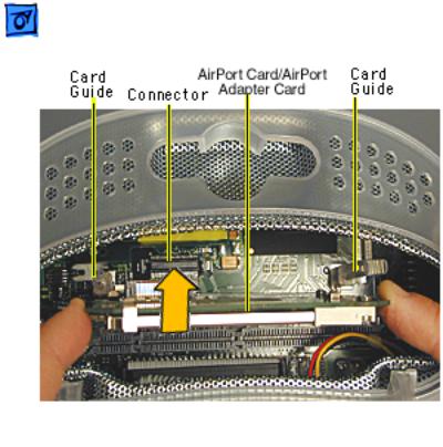
2. Remove the AirPort Card by lifting the card straight up and out of the card guides and connector.
Take Apart |
AirPort Card - 21 |
|
|
|
|
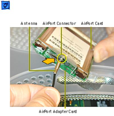
3. Disconnect the antenna from the small hole AirPort Card.
Take Apart |
AirPort Card - 22 |
|
|
|
|
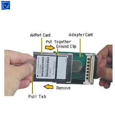
4. Remove the ground clip from the AirPort Adapter Card.
5. Using the pull tab, separate the AirPort Card from the adapter card.
Take Apart |
CD/HD Carrier - 23 |
|
|
|
|
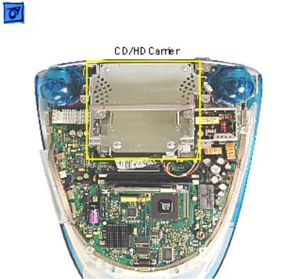
CD/HD Carrier
Before you begin, position the computer upside down, resting the computer on an ESD mat or other soft surface and remove the following:
• bottom housing
• EMI cover
• SDRAM
Take Apart |
CD/HD Carrier - 24 |
|
|
|
|
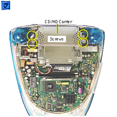
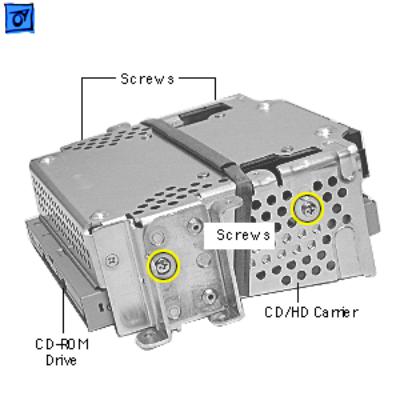
1. Remove the four screws connecting the CD/HD drive carrier to the metal chassis (also known as the divider panel).
 01 Service Manual")
Take Apart |
CD/HD Carrier - 25 |
|
|
|
|
2. Disconnect the following cables fro the back of the CD/HD carrier:
• hard drive power cable
• hard drive data cable
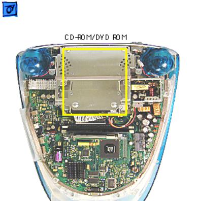
• CD-ROM/DVD-ROM data cable
• logic board cable connector
Take Apart |
CD/HD Carrier - 26 |
|
|
|
|
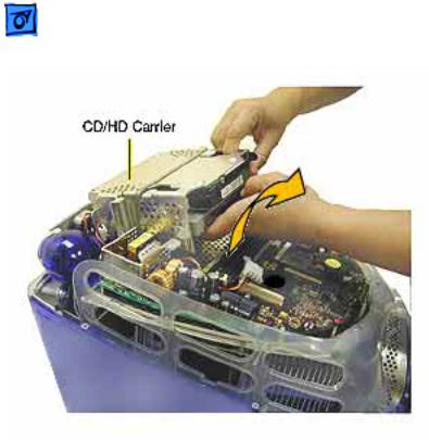
3. Tilt the CD/HD carrier forward and lift the carrier out of the computer.
Note: Continue with the Take Apart procedures if you are replacing the CD-ROM, DVD-ROM, or the hard drive.
Take Apart |
CD-ROM / DVD-ROM/CD-RW - 27 |
|
|
|
|
CD-ROM / DVD-
ROM/CD-RW
Note: The procedures for removing a CD-ROM, DVDROM and CD-RW are identical. This procedure will reference the CD-ROM Take Apart.
Before you begin, position the computer upside down, and remove the following:
• bottom housing
• EMI cover
• SDRAM
• CD/HD carrier
Take Apart |
CD-ROM / DVD-ROM/CD-RW - 28 |
|
|
|
|
1. Using a Phillips screwdriver, remove the CD/HD carrier mounting screws (two on each side).
Loading...