


 Loading...
Service Source
iMac (17-inch Flat Panel, 1GHz)
© 2003 Apple Computer, Inc. All rights reserved.

iMac (17-inch Flat Panel, 1GHz) |
- 1 |
Service Source
Take Apart
iMac (17-inch Flat Panel, 1GHz)
© 2003 Apple Computer, Inc. All rights reserved.

General Information
Overview
Some of the key features that distinguish this computer from the earlier iMac (Flat Panel) models include:
•This computer uses double-data rate (DDR) memory. Memory from previous iMac models is not compatible with this computer. Do not use older SDRAM DIMMs or SODIMMs even if they fit into the slot.
•There is an audio line in jack.
•Bluetooth and AirPort Extreme Card are CTO options.
New Procedures
If you are familiar with taking apart iMac (Flat Panel) computers, the procedures haven’t changed much; however, you will notice some difference with this model:
•The diagnostic test points have moved on the bottom of the logic board. They are now located near the AirPort card. Refer to the topic, “Diagnostic Test Points” in this chapter for more information.
•The neck extension is different. The inverter, speaker, and fan cables are part of the neck extension cables, replacing the blind mate connector.
•There are separate data cables for the optical and hard drive.
•A clutch assembly was added to the door so it closes slower now.
•The Pangea heatsink on the logic board is about two inches longer.
•The diagnostic tool kit (cables), 076-0897, is not required anymore. The cables reach the logic board when the computer is in the open position; however, you may want to place something underneath the bottom housing (to prop it up) when the unit is open to give the cables some slack.
Tools
The following tools are recommended for the take apart procedures.
•The service stand (076-0898)
•Thermal paste (922-4757)
•Torque driver (076-0899)
•1.5 mm hex driver (for LCD bezel screws)
•#0 Phillips screwdriver)
•Torx screwdriver set (6, 8, 10, 15)
•Plastic flatblade screwdriver or stylus (922-5065)
•Needlenose pliers
•ESD wriststrap and mat
General Information |
iMac (17-inch Flat Panel, 1GHz) Take Apart - 1 |

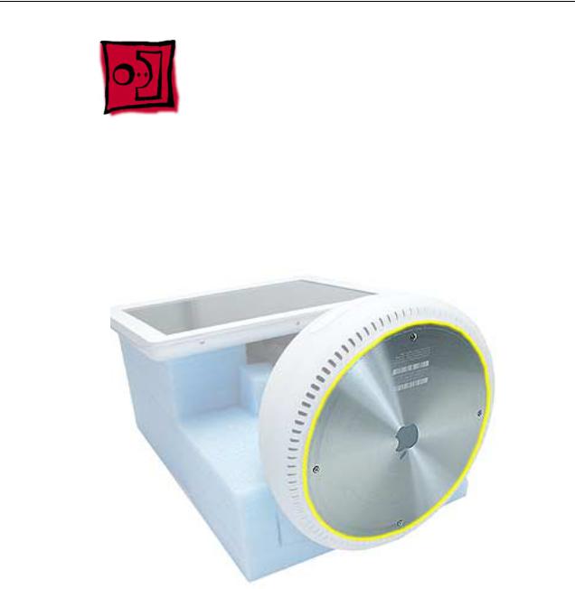
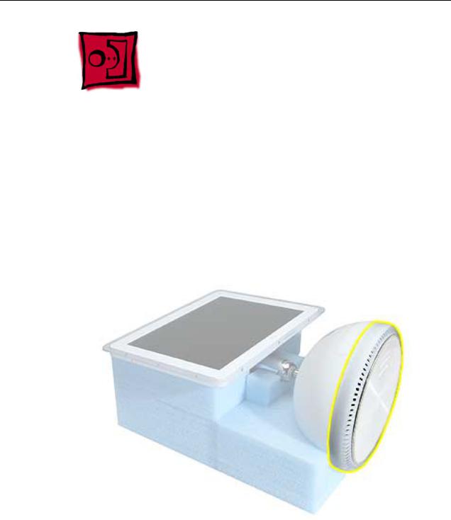
Service Stand
1.Support the computer by neck and the base (A). Gently position the computer in the service stand with the flat panel facing up (B).
2.Note: The base of the computer can be rotated when servicing internal parts.
2 - iMac (17-inch Flat Panel, 1GHz) Take Apart |
General Information |
User Access Plate
Tools
This procedure requires the following tools:
• Phillips #0 screwdriver
Part Location
Preliminary Steps
Before you begin, do the following:
• Position the computer in the service stand.
User Access Plate |
iMac (17-inch Flat Panel, 1GHz) Take Apart - 3 |
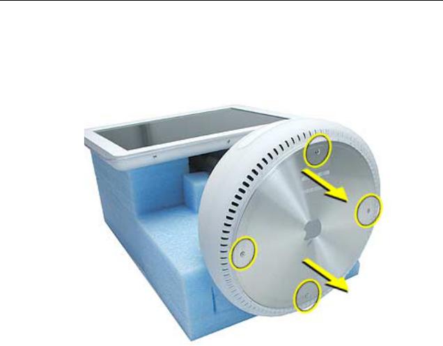
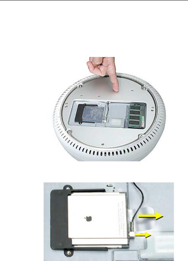
Procedure
1.Loosen the four captive screws on the access panel.
2.Remove the panel by grabbing onto two captive screws and lift the panel off the base.
4 - iMac (17-inch Flat Panel, 1GHz) Take Apart |
User Access Plate |
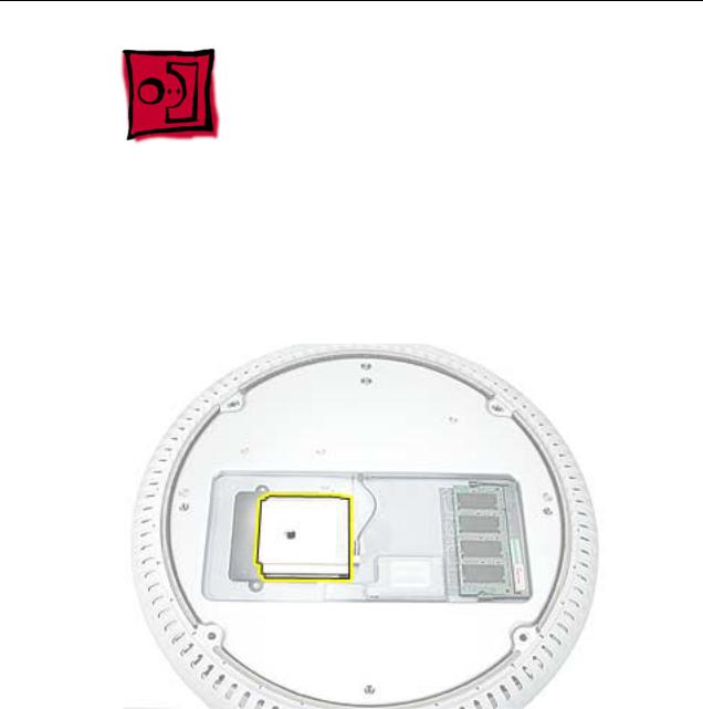
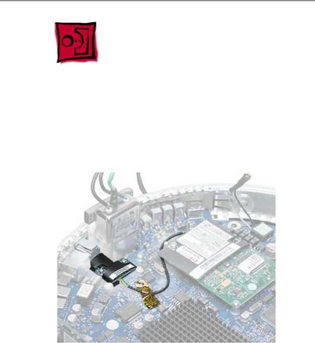
AirPort Extreme Card
Tools
This procedure requires no tools.
Part Location
Preliminary Steps
Before you begin, do the following:
•Position the computer in the service stand.
•Remove the user access plate.
AirPort Extreme Card |
iMac (17-inch Flat Panel, 1GHz) Take Apart - 5 |
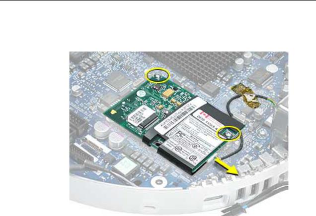
Procedure
1.Unplug all cables from the computer except the power cord.
2.Important: To avoid electrostatic discharge, always ground yourself by touching metal before you touch any parts or install any components inside the computer. To avoid static electricity building back up in your body, do not walk around the room until you have completed the installation and closed the computer.
3.Touch a metal surface inside the computer to ground yourself.
4.Unplug the power cord.
5.Pull the plastic tab on the AirPort Extreme card to remove it from the slot. Disconnect the AirPort antenna from the card.
6 - iMac (17-inch Flat Panel, 1GHz) Take Apart |
AirPort Extreme Card |
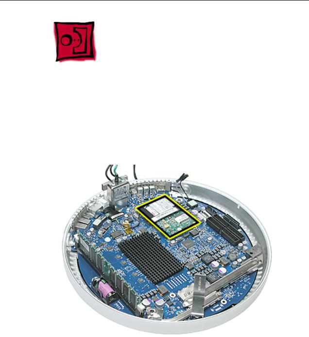
Memory, SO-DIMM (userinstallable)
Tools
No tools are required for this procedure.
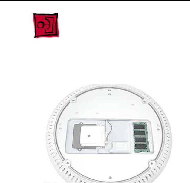
Part Location
Preliminary Steps
Before you begin, do the following:
•Position the computer in the service stand.
•Remove the user access plate.
Note: DIMMs used in this slot should be a low-profile PC2100 (DDR266) SO-DIMM. Only the SO-DIMM slot is accessible by the user.
Memory, SO-DIMM (user-installable) |
iMac (17-inch Flat Panel, 1GHz) Take Apart - 7 |
Procedure
1.Unplug all cables from the computer except the power cord.
2.Important: To avoid electrostatic discharge, always ground yourself by touching metal before you touch any parts or install any components inside the computer. To avoid static electricity building back up in your body, do not walk around the room until you have completed the installation and closed the computer.
3.Touch a metal surface inside the computer to ground yourself.
4.Unplug the power cord.
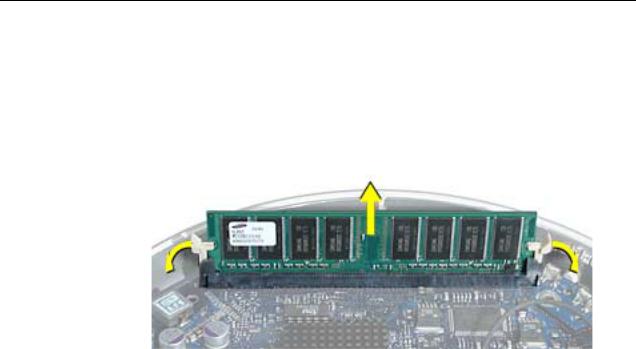
5.Release the memory by spreading apart the tabs in the expansion slot from the notches in the card.
8 - iMac (17-inch Flat Panel, 1GHz) Take Apart |
Memory, SO-DIMM (user-installable) |
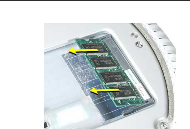
6. Allow the memory to pop up slightly, and pull it out of the memory slot.
Memory, SO-DIMM (user-installable) |
iMac (17-inch Flat Panel, 1GHz) Take Apart - 9 |
Bottom Housing
Tools
This procedure requires the following tools:
• Torx-15 screwdriver
Part Location
Preliminary Steps
Before you begin, do the following:
•Position the computer in the service stand.
•Remove the user access plate.
10 - iMac (17-inch Flat Panel, 1GHz) Take Apart |
Bottom Housing |
Procedure
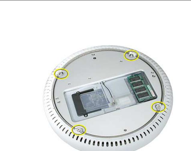
1.When opening the bottom housing, rotate the base so the optical drive door is on the right. (This position is less stressful on the internal cables when the bottom is open).
2.Remove the four torx screws.
Replacement Note: These torx screws must be tightened to at least 17 in.-lbs. If you do not have a torque driver, you will have to make sure these screws are tightened by hand FIRMLY, BUT NOT FORCIBLY. Or, purchase the service tool (076-0899) in order to ensure the thermal pipe is firmly mated with the top base. If the bottom housing is not securely attached to the base in this fashion, the CPU may overheat and become damaged. For more information, refer to “Thermal Paste Application’” in this chapter. Rotate the base so that the optical drive door is on the right.
iMac (17-inch Flat Panel, 1GHz) Take Apart - 11
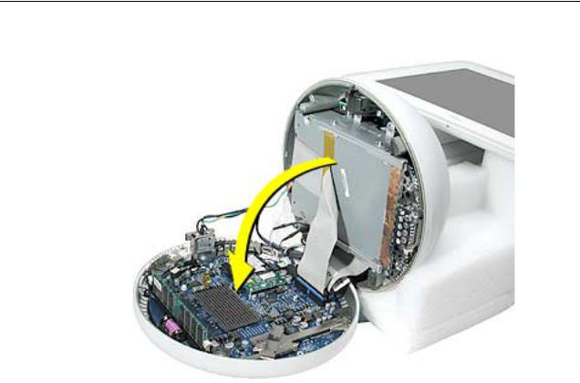
3. Gently open the bottom housing in the direction of the arrow. Disconnect the cables.
12 - iMac (17-inch Flat Panel, 1GHz) Take Apart
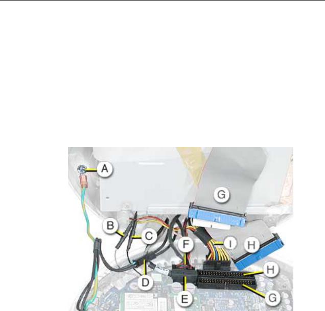
4.Disconnect the following:
A Grounding screw
B Bluetooth connector (if present)
C AirPort connector
D AC line filter connector
E TMDS video connector
F Inverter, speaker, fan connector
G Optical cable and connector
H Hard drive cable and connector
I Power Supply connector
5. Set the bottom housing aside.
Warning: Whenever the bottom housing is opened for service, you must do two things:
1.You must clean the original thermal film from all thermal interface mating surfaces, and reapply thermal paste to the mating surfaces on the thermal pipe.
2. You must tighten the four torx screws on the bottom housing to a minimum of 17 in.-lbs. Use a torque driver (service tool 076-0899) to ensure that the thermal pipe is firmly mated with the top base. If you do not have a torque driver, you must make sure the screws are tightened by hand FIRMLY, BUT NOT FORCIBLY.
Failure to follow these steps could cause the computer to overheat and damage internal components.
Refer to the topic “Thermal Paste Application” for detailed information.
iMac (17-inch Flat Panel, 1GHz) Take Apart - 13
Thermal Paste Application
Tools
This procedure requires the following tools:
•Plastic stylus or plastic spatula to remove the old thermal paste
•Plastic stylus or plastic spatula to spread the thermal paste
•Thermal paste (922-4757)
Part Location
14 - iMac (17-inch Flat Panel, 1GHz) Take Apart |
Thermal Paste Application |
 03 Service Manual")
Procedure
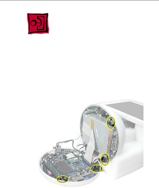
1.Thoroughly clean the original thermal film from the mating surfaces (circled below) of the bottom housing and thermal pipe. Use a plastic stylus to scrape the surfaces clean. Note: Do not use an abrasive material or liquid cleaner.
2. Squeeze a ball of thermal paste onto the mating surfaces of the thermal pipe.
Thermal Paste Application |
iMac (17-inch Flat Panel, 1GHz) Take Apart - 15 |

3. Replace the bottom housing.
Warning: The bottom housing has four torx screws that must be tightened to at least 17 in.-lbs. Use a torque driver (service tool 076-0899) to ensure that the thermal pipe is firmly mated with the top base. If you do not have a torque driver, you must make sure the screws are tightened by hand FIRMLY, BUT NOT FORCIBLY.
Failure to apply the thermal paste as described in this procedure, and failure to tighten the torx screws as directed, could cause the computer to overheat and damage internal components.
Refer to the topic “Thermal Paste Application” for detailed information.
16 - iMac (17-inch Flat Panel, 1GHz) Take Apart |
Thermal Paste Application |
RJ-11 Modem Filter Board
Tools
This procedure requires the following tools:
• Torx-6 screwdriver
Part Location
Preliminary Steps
Before you begin, do the following:
•Position the computer in the service stand.
•Remove the user access plate.
•Remove the bottom housing.
RJ-11 Modem Filter Board |
iMac (17-inch Flat Panel, 1GHz) Take Apart - 17 |
Procedure
1. Remove two screws and disconnect the cable from the modem.
2. Remove the RJ-11 board from the I/O port.
Warning: Whenever the bottom housing is opened for service, you must do two things:
1.You must clean the original thermal film from all thermal interface mating surfaces, and reapply thermal paste to the mating surfaces on the thermal pipe.
2. You must tighten the four torx screws on the bottom housing to a minimum of 17 in.-lbs. Use a torque driver (service tool 076-0899) to ensure that the thermal pipe is firmly mated with the top base. If you do not have a torque driver, you must make sure the screws are tightened by hand FIRMLY, BUT NOT FORCIBLY.
Failure to follow these steps could cause the computer to overheat and damage internal components.
Refer to the topic “Thermal Paste Application” for detailed information.
18 - iMac (17-inch Flat Panel, 1GHz) Take Apart |
RJ-11 Modem Filter Board |
Modem
Tools
This procedure requires the following tools:
• Torx-8 screwdriver
Part Location
Preliminary Steps
Before you begin, do the following:
•Position the computer in the service stand.
•Remove the user access plate.
•Remove the bottom housing.
Modem |
iMac (17-inch Flat Panel, 1GHz) Take Apart - 19 |
Procedure
1. Remove two screws and disconnect the cable.
2. Lift the modem board from the connector on the logic board.
Warning: Whenever the bottom housing is opened for service, you must do two things:
1.You must clean the original thermal film from all thermal interface mating surfaces, and reapply thermal paste to the mating surfaces on the thermal pipe.
2. You must tighten the four torx screws on the bottom housing to a minimum of 17 in.-lbs. Use a torque driver (service tool 076-0899) to ensure that the thermal pipe is firmly mated with the top base. If you do not have a torque driver, you must make sure the screws are tightened by hand FIRMLY, BUT NOT FORCIBLY.
Failure to follow these steps could cause the computer to overheat and damage internal components.
Refer to the topic “Thermal Paste Application” for detailed information.
20 - iMac (17-inch Flat Panel, 1GHz) Take Apart |
Modem |
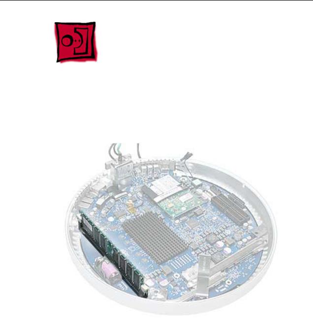
Memory (factory-installed)
Tools
This procedure requires the following tools:
• No tools are required
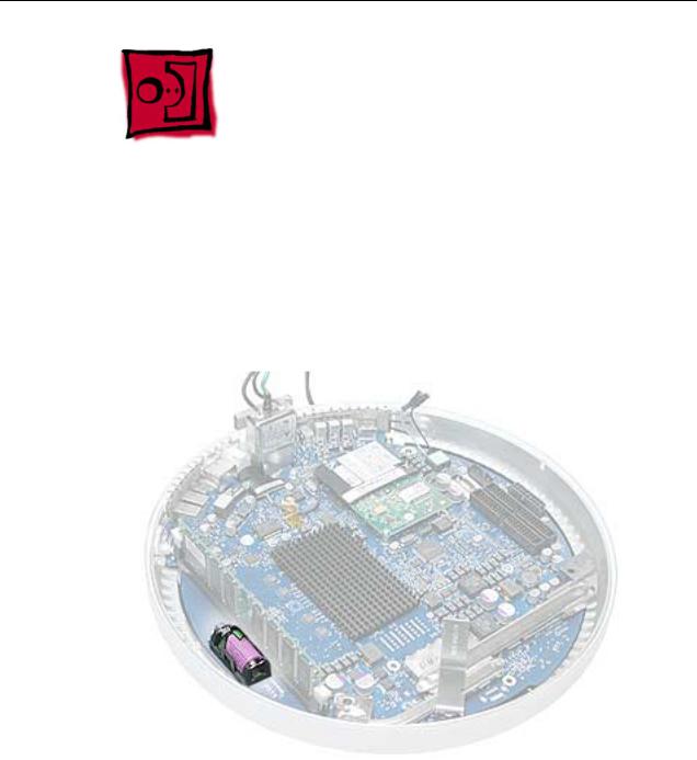
Part Location
Preliminary Steps
Before you begin, do the following:
•Position the computer in the service stand.
•Remove the user access plate.
•Remove the bottom housing.
Memory (factory-installed) |
iMac (17-inch Flat Panel, 1GHz) Take Apart - 21 |
Procedure
1.Push down on the ejector tabs to release the memory module.
2.Pull the memory up and out of the slot. Important: Make sure that the memory installed on the logic board is compatible with the system. The computer accepts double-data rate (DDR) SDRAM DIMMs. DIMMs used in this slot must fit the following specification: PC2100 SDRAM DDR266 DIMMs for 133 MHz systems.
Warning: Whenever the bottom housing is opened for service, you must do two things:
1.You must clean the original thermal film from all thermal interface mating surfaces, and reapply thermal paste to the mating surfaces on the thermal pipe.
2. You must tighten the four torx screws on the bottom housing to a minimum of 17 in.-lbs. Use a torque driver (service tool 076-0899) to ensure that the thermal pipe is firmly mated with the top base. If you do not have a torque driver, you must make sure the screws are tightened by hand FIRMLY, BUT NOT FORCIBLY.
Failure to follow these steps could cause the computer to overheat and damage internal components.
Refer to the topic “Thermal Paste Application” for detailed information.
22 - iMac (17-inch Flat Panel, 1GHz) Take Apart |
Memory (factory-installed) |
Battery
Tools
This procedure requires the following tools:
• No tools are required
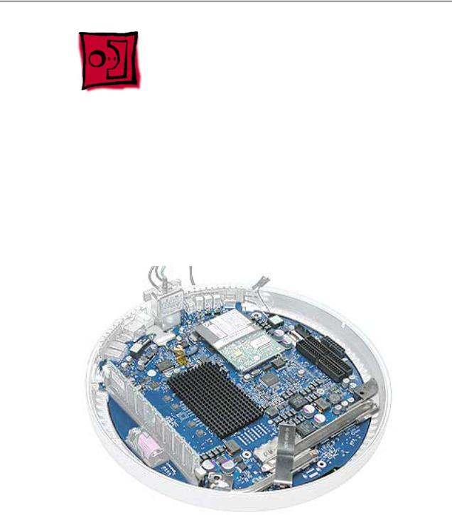
Part Location
Preliminary Steps
Before you begin, do the following:
•Position the computer in the service stand.
•Remove the user access plate.
•Remove the bottom housing.
Battery |
iMac (17-inch Flat Panel, 1GHz) Take Apart - 23 |
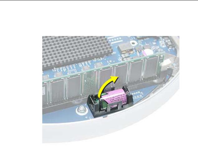
Procedure
1. Using a flatblade screwdriver, gently pry the battery from the battery holder.
Warning: Whenever the bottom housing is opened for service, you must do two things:
1.You must clean the original thermal film from all thermal interface mating surfaces, and reapply thermal paste to the mating surfaces on the thermal pipe.
2. You must tighten the four torx screws on the bottom housing to a minimum of 17 in.-lbs. Use a torque driver (service tool 076-0899) to ensure that the thermal pipe is firmly mated with the top base. If you do not have a torque driver, you must make sure the screws are tightened by hand FIRMLY, BUT NOT FORCIBLY.
Failure to follow these steps could cause the computer to overheat and damage internal components.
Refer to the topic “Thermal Paste Application” for detailed information.
24 - iMac (17-inch Flat Panel, 1GHz) Take Apart |
Battery |
Logic Board
Tools
This procedure requires the following tools:
•Phillips #2 screwdriver (for the plastic screw)
•Torx-15 screwdriver
Part Location
Note: The battery, RJ-11 board, AirPort card, modem, I/O port covers, and memory (on the top and the bottom of the logic board) need to be removed from the logic board before returning the board to Apple for service.
Preliminary Steps
Before you begin, do the following:
•Position the computer in the service stand.
•Remove the user access plate.
•Remove the bottom housing.
•Remove the RJ-11 board.
Logic Board |
iMac (17-inch Flat Panel, 1GHz) Take Apart - 25 |
Procedure
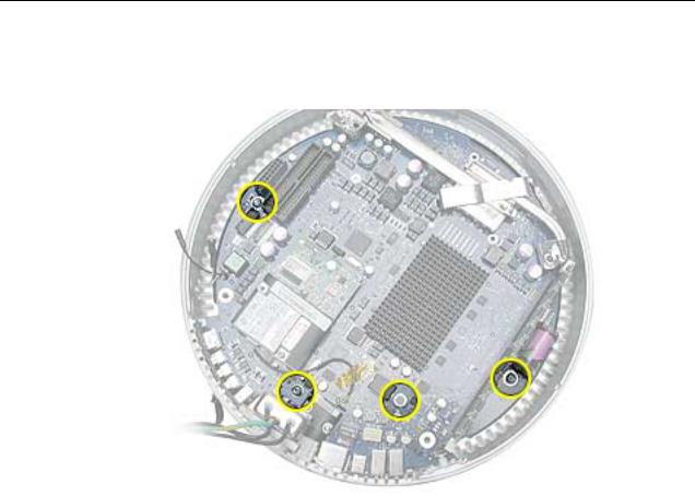
1. Remove the three torx screws (metal) and one plastic screw.
26 - iMac (17-inch Flat Panel, 1GHz) Take Apart |
Logic Board |
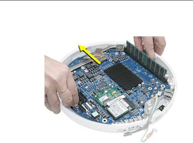
2.Grab the logic board by the battery retainer and the hard drive connector. Lift the board slightly and pull back to release the board from the bottom housing and I/O ports. Note: The I/O port covers may come out with the logic board when it’s removed.
3. Remove the I/O port covers from the logic board.
Warning: Whenever the logic board is separated from the bottom housing, you must install new thermal pads to three surfaces on the bottom housing. Failure to apply these pads whenever the logic board is separated from the bottom housing could cause these parts to overheat and could damage internal components.
Note: AFTER installing new thermal pads, if you must briefly re-separate the logic board from the housing, it is OK to retain the same, new pads as long as they are not handled excessively. Refer to “Thermal Pad Installation” in this chapter for detailed information.
Warning: Whenever the bottom housing is opened for service, you must do two things:
1.You must clean the original thermal film from all thermal interface mating surfaces, and reapply thermal paste to the mating surfaces on the thermal pipe.
2. You must tighten the four torx screws on the bottom housing to a minimum of 17 in.-lbs. Use a torque driver (service tool 076-0899) to ensure that the thermal pipe is firmly mated with the top base. If you do not have a torque driver, you must make sure the screws are tightened by hand FIRMLY, BUT NOT FORCIBLY.
Failure to follow these steps could cause the computer to overheat and damage internal components.
Refer to the topic “Thermal Paste Application” for detailed information.
Logic Board |
iMac (17-inch Flat Panel, 1GHz) Take Apart - 27 |
Loading...