


 Loading...
Apple Technician Guide
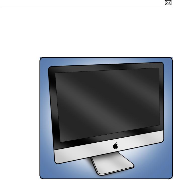
iMac (27-inch, Mid 2010)
2010-09-09

Apple Inc.
© 2010 Apple Inc. All rights reserved.
Under the copyright laws, this document may not be copied, in whole or in part, without the written consent of Apple.
Every effort has been made to ensure that the information in this document is accurate. Apple is not responsible for printing or clerical errors.
Apple
1 Infinite Loop Cupertino, CA 95014-2084 USA
+ 1 408 996 1010 www.apple.com
Apple, the Apple logo, Mac, and Macintosh are trademarks of Apple Inc., registered in the U.S. and other countries.

iMac (27-inch, Mid 2010)
Contents
About This Guide
Updates 10
Updated 9 September 2010 10 Updated 9 August 2010 10
Apple Technician Guide introduced 27 July 2010 10
Feedback 10
Basics
Overview 12
Identifying Features 13 |
|
|
Product Configurations |
13 |
|
Safety Precautions |
14 |
|
Serial Number Location |
15 |
|
New Accessories |
16 |
|
Magic Trackpad |
16 |
|
Apple Battery Charger |
18 |
|
Troubleshooting
General Troubleshooting |
20 |
|
Wireless Troubleshooting |
20 |
|
Update System Software & Firmware 20 |
||
Troubleshooting Theory |
20 |
|
Hardware vs. Software |
21 |
|
Common Reset Procedures 21 |
||
Power On Self Test (POST) |
21 |
|
Resetting the System Management Controller (SMC) 22 |
||
Resetting Parameter RAM (PRAM) 22 |
||
Starting Up in Safe Mode |
23 |
|
Removing the Battery, Measuring DC Voltage 24
Diagnostics 25
Sensors Errors 25
Sensor Locations 27
Diagnostic LEDs 29
Location of Diagnostic LEDs 29

LED Functions |
30 |
|
LED Startup Sequence |
31 |
|
Logic Board Test Points |
32 |
|
Functional Overview 33 |
||
Block Diagram |
34 |
|
Symptom Charts 35
Startup and Power 35
No Power, Dead Unit 35 Won’t Start Up 37 Intermittent Shutdown 39
Kernel Panic, System Crashes 44 No Video 46
Corrupted Video 48
Burnt Smell/Odor 51 Uncategorized Symptoms 52
Display 53
Backlight Issue/No Backlight 53
Noise / Unstable Flickering 55 LCD Image Issues 58 Incorrect/Missing Colors 60 Distorted/Blurred Image 62 Pixel Anomalies 64 Vertical/Horizontal Lines 66
Non-Uniform Brightness / Color 68 Cosmetic Defects 69 Uncategorized Symptoms 69
Mass Storage 70
Hard Drive Not Recognized 70
Optical Drive Not Recognized 76
Optical Drive Won’t Accept/Eject Media 77 Optical Drive Read/Write Error 78
Optical Drive Not Performing to Specifications 80 Optical Drive Noisy 82
SD Card Will Not Insert Into Slot 83 SD Card Not Recognized 84 Uncategorized Symptoms 85
Communications 86
AirPort/Bluetooth Issues 86
AirPort Card Kernel Panic 89
Ethernet Port/Device Issue 90 Wireless Input Device Does Not Pair 91 Uncategorized Symptoms 93
Input/Output Devices 94
Apple Remote Inoperable 94
Audio:Microphone 96

Audio:Built-in Speakers Have Distorted Sound |
97 |
||
Audio:No Audio from Built-in Speakers |
98 |
|
|
Camera Issues 101 |
|
|
|
FireWire Device Not Recognized 102 |
|
|
|
USB Device Not Recognized |
104 |
|
|
Wired Keyboard Does Not Function Properly |
106 |
||
Keyboard:Specific Keys Do Not Respond |
108 |
|
|
Wired Keyboard/Mouse Not Recognized |
108 |
|
|
Wireless Input Device Does Not Pair 110 |
|
||
Apple Wireless Mouse/Magic Trackpad Erratic Tracking 113 |
|||
Wireless Input Device Loses Connection |
114 |
|
|
Apple Battery Charger Does Not Charge Batteries 116 |
|||
Mechanical 118 |
|
|
|
Noise/Hum/Vibration 118 |
|
|
|
Fan Failures / Thermal Issues |
121 |
|
|
Stand/Hinge Issues 122 |
|
|
|
Physical Damage 123 |
|
|
|
Uncategorized Symptoms 123 |
|
|
|
Take Apart
General Information |
125 |
|
Opening the Unit 125 |
|
|
Required Tools 125 |
|
|
Required Special Tools for Glass Panel |
126 |
|
Cleaning Tools Starter Kit 126 |
|
|
Cleaning & Handling the Glass Panel |
127 |
|
Do’s and Don’ts 127 |
|
|
Handling a Broken Glass Panel 128 |
|
|
How to Remove a Broken Glass Panel |
128 |
|
Safety 133 |
|
|
Logic Board Handling 134 |
|
|
Reassembly Steps |
134 |
|
Note About Images in This Manual 134
Screw Sizes 134
Access Door 135
Memory 137
Removal 138
Reassembly 138
Glass Panel 139
Removal 140
Reassembly 141

Camera 144
Removal 145
Reassembly 146
LCD Panel |
147 |
|
|
|
|
Removal |
148 |
|
|
|
|
Handling the Panel |
153 |
||||
Reassembly |
154 |
|
|
||
Vertical Sync Cable (Vsync) 157 |
|||||
LED Temp Sensor Cable |
158 |
||||
DisplayPort Cable |
159 |
|
|||
Audio Ports and Cable |
161 |
||||
AirPort Antenna |
163 |
|
|
||
AirPort Card |
165 |
|
|
|
|
AirPort Carrier Board |
167 |
||||
AirPort Cable |
169 |
|
|
||
Bluetooth Antenna 171 |
|||||
Bluetooth Board |
173 |
|
|
||
LED Backlight Board |
175 |
||||
Power Supply |
177 |
|
|
||
Removal |
178 |
|
|
|
|
Reassembly |
179 |
|
|
||
Backlight Pressure Wall |
180 |
||||
Power Supply/Hard drive Pressure Wall 182
Removal 183
Reassembly 183
Hard Drive 185
Removal 186
Reassembly 187
Hard Drive Sensor Cable 188
Removal 189
Reassembly 189
Optical Drive 190
Removal 191

Reassembly 193
Optical Sensor Cable 195
Optical Drive Fan 197
SD Card Reader 199
Removal 200
Reassembly 201
SD Card Reader Cable 202
IR Board and Cable 204
Logic Board 206
Removal |
207 |
|
Handling the Logic Board 209 |
||
Reassembly |
210 |
|
Video Card |
216 |
|
Solid State Drive (SSD) 219 |
||
Removal |
220 |
|
Reassembly |
222 |
|
SSD Data Cable 223
Optical/MXM Pressure Wall 225
Hard Drive Data Cable 227
Optical Drive Data Cable 230
Battery 232
Removal 233
Reassembly 233
Right Speaker 234
CPU Fan 236
Removal 237
Reassembly 238
Ambient Temp Sensor 239
Removal 240
Reassembly 240
Left Speaker 241
Removal 242
Reassembly 242
Hard Drive Fan 244
Mechanism Cover 246

Stand 248
Removal 249
Reassembly 250
Mechanism 252
Bluetooth Cable 254
Camera Cable 257
Cable, AC/DC Power/Backlight/SATA 260
Cable, AC/DC Power/Backlight/SATA, SSD 262
Microphone Cable 265
Rear Housing 266
Reassembly 267
Additional Procedures
Retrieving Mechanism 272
Views
Exploded Views 277
Exploded View #1 277
Exploded View #2 278
Exploded View #3 279
External Views 280
Rear View 280
Ports 281
Internal Views 282
Photo of Components below LCD 282
Photo of Components in the Rear Housing 283
Logic Board, Front Side |
284 |
Logic Board, Back Side |
285 |
Screw Chart 286

Apple Technician Guide
About This Guide
iMac (27-inch, Mid 2010)
© 2009 Apple Inc. All rights reserved.

Updates
Updated 9 September 2010
Troubleshooting:
•Display:several symptoms:Modified steps to allow unit to warm up for about a minute (instead of 15 minutes) before evaluating front-of-screen performance.
Take Apart:
•LCD Panel:Added note that overtightening screws could lead to issue of light leakage after unit is reassembled.
•Camera and Rear Housing:Added note that white thermal paste intended for camera should not be used for any other purpose (such as portable computer heatsinks).
Updated 9 August 2010
•Basics:Overview:New Accessories:Magic Trackpad and Apple Battery Charger:Added links to the User Guides:
Apple Technician Guide introduced 27 July 2010
Feedback
We want your feedback to help improve this and future Technician Guides! Please email any comments to smfeedback2@apple.com
2010-09-09 |
iMac (27-inch, Mid 2010) About This Guide — Updates 10 |
Apple Technician Guide
Basics
iMac (27-inch, Mid 2010)
© 2010 Apple Inc. All rights reserved.
Overview
Introducing the iMac (27-inch, Mid 2010) with the latest Intel Core i3, Core i5 and Core i7 processors and powerful new graphics.The new iMac line is the fastest ever with dual-core processor speeds up to 3.6 GHz, quad-core speeds up to 2.93 GHz and discrete graphics including the powerful ATI Radeon HD 5750.
The processors feature an integrated memory controller to access the system memory directly, allowing the new iMac to take full advantage of its faster 1333 MHz memory. New discrete ATI Radeon HD processors deliver incredibly smooth, crisp graphics for the most demanding 3D games, creative software and technical applications. Refer to the next page for more features.
2010-09-09 |
iMac (27-inch, Mid 2010) Basics — Overview 12 |

Identifying Features
The iMac (27-inch, Late 2010) computer features include:
•27-inch display 2560 x 1440 LED-backlit display
•Increased processor speeds:
•3.20 GHz Intel Core i3 with 4MB shared L3 cache
•2.80 GHz Intel Core i5 (CTO)
•3.60 GHz Quad-Core Intel Core i5 with 8MB shared L3 cache
•2.93 GHz Quad-Core Intel Core i7 (CTO)
•4 GB 1333 MHz DDR3 SDRAM expandable up to 16GB
•Main memory PC3-10600, DDR3 (1333), 204-pin, ships with 2x1333 MHz SO-DIMMs
•SD card reader slot with SDXC (Secure Digital Extended Capacity) supports 32GB - 2TB
•Mini DisplayPort output (DVI,VGA, and dual-link DVI) and supports input from external DisplayPort sources (adapters sold separately)
•Graphics and video support:
•AMD Radeon HD 5670 graphics processor with 512MB GDDR3
•AMD Radeon HD 5750 graphics processor with 1 GB GDDR5
•Hard drive:1TB, 2TB
•Solid State Drive options:
•256GB SSD (SSD only, without a hard drive)
•256GB SSD + 1TB Serial ATA Hard Drive (CTO)
•256GB SSD + 2TB Serial ATA Hard Drive (CTO)
•Magic Mouse (Mid 2010) and Apple Wireless Keyboard (2009), standard with all configurations
•Ships with and requires at least Mac OS 10.6.3
•Magic Trackpad (CTO)
•Apple Battery Charger (CTO)
Product Configurations
For product configurations, refer to Apple Support Tech Specs:http://support.apple.com/ specs/
2010-09-09 |
iMac (27-inch, Mid 2010) Basics — Overview 13 |

Safety Precautions
WARNING: HIGH VOLTAGE:The AC/DC power supply PCB remains powered up whenever the system is plugged in, whether or not the system has been turned on. Use extreme caution when troubleshooting the system with the front bezel removed.
Important: If the computer is shut down by removing the power cord, allow the power supply a good 2-3 minutes to discharge the capacitors before handling it. However, if you select“Shut Down”via the Apple menu, the computer will discharge the power supply capacitor almost immediately.
2010-09-09 |
iMac (27-inch, Mid 2010) Basics — Overview 14 |
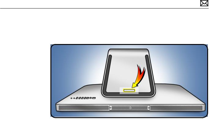
Serial Number Location
The iMac (27-inch, Mid 2010) serial number is located on the base of the stand.When replacing a stand, transfer the serial number to the new stand.
2010-09-09 |
iMac (27-inch, Mid 2010) Basics — Overview 15 |
New Accessories
Magic Trackpad
The wireless Magic Trackpad uses Bluetooth® technology to connect to the Mac and comes with two AA batteries installed.To use the Magic Trackpad and its full features, update your Mac to Mac OS X version 10.6.4 or later, and then install the latest trackpad software using Software Update, if needed. Refer to the Magic Trackpad Quick Start Guide for more information.
Note:If for some reason the iMac (27-inch, Mid 2010) needs the system software reinstalled, pair the Magic Trackpad and then run Software Update. If for some reason you notice that only basic functionality is present on the Magic Trackpad, ensure that it’s paired correctly before launching Software Update. Refer to the following Kbase articles for more information.
•HT4273 About Magic Trackpad Update 1.0 for Windows
•HT4254 About Magic Trackpad and Multi-Touch Trackpad Update 1.0
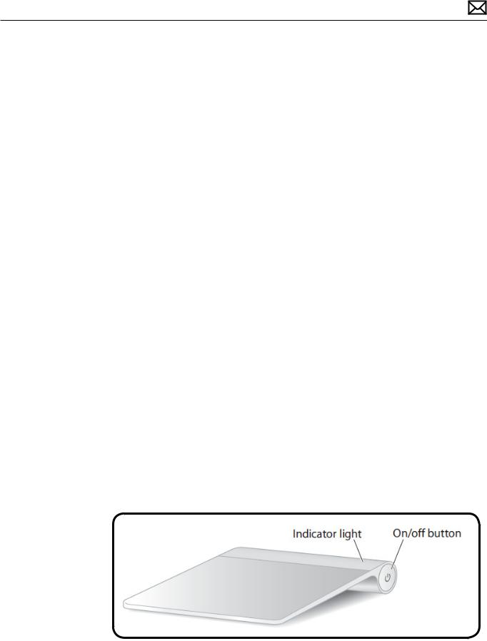
About the Indicator Light
The indicator light displays the status of your Magic Trackpad and the batteries.
•When you first turn your trackpad on, the indicator light glows steadily for 2 to 3 seconds, indicating the batteries are good.
•If your trackpad isn’t paired with a Mac, the light blinks, indicating your trackpad is in discovery mode and ready to pair (pairing means connecting your trackpad and Mac to each other wirelessly).
•If you don’t pair your trackpad with your Mac within 3 minutes, the light and trackpad turn off to conserve battery life. Press the On/off button on your trackpad to turn it on again, allowing you to pair it with your Mac.
•When your trackpad is on and connected, the indicator light turns off.
Turn on the Trackpad
•To turn the trackpad on, press firmly and release the on/off button.
•To turn on the trackpad and make it stay in discovery mode (prevent auto-pairing to previous known host), press and hold the on/off button.
2010-09-09 |
iMac (27-inch, Mid 2010) Basics — Overview 16 |
Pairing the Magic Trackpad
To pair your trackpad:
1.Choose Apple ( ) > System Preferences, and then click Trackpad.
2.Click“Set Up Bluetooth Trackpad …”in the lower-right corner.
3.Press the On/off button on your trackpad to turn it on.
4.Click Continue when your trackpad is detected.
Once your trackpad is paired with your Mac, use Software Update again to make sure you have the latest software installed.
Note:If the iMac (27-inch, Mid 2010) needs to have system software reinstalled for some reason, pair the Magic Trackpad and then run Software Update. If for some reason you notice that only basic functionality is present on the Magic Trackpad, ensure that it’s paired correctly before launching Software Update.
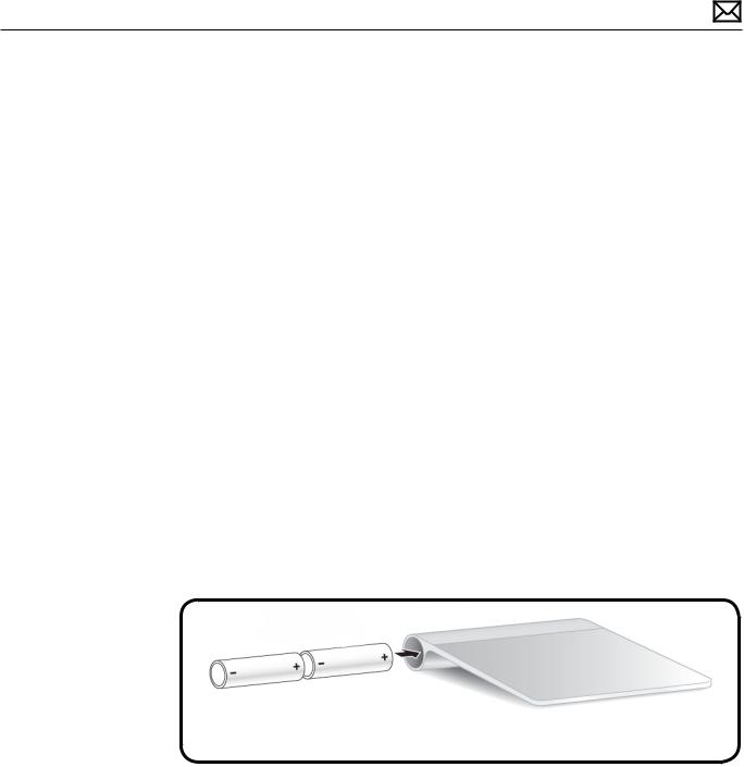
Installing Batteries
1.Use a coin to remove the battery compartment cover on the left side.
2.Insert batteries into the battery compartment as shown.
Warning:Replace or recharge batteries at the same time. Don’t mix old batteries with new batteries and don’t mix battery types (for example, alkaline and lithium batteries). Don’t open or puncture the batteries, install them backwards, or expose them to fire, high temperatures, or water. Don’t charge nonrechargeable AA batteries. Keep batteries out of the reach of children.
2010-09-09 |
iMac (27-inch, Mid 2010) Basics — Overview 17 |
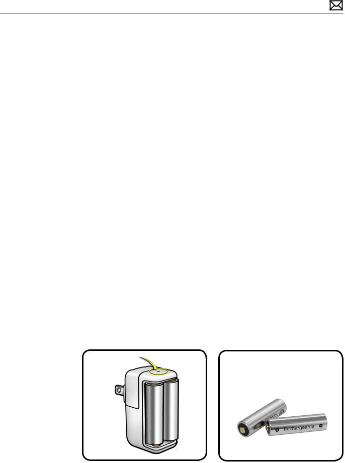
Apple Battery Charger
Use the Apple Battery Charger to charge rechargeable NiMH batteries for your Apple products that use AA batteries. Each Apple Battery Charger comes with six high-performance AA NiMH batteries:two for your keyboard, two for your mouse or trackpad, and two for charging.You can use the Apple Battery Charger to charge either one or two NiMH rechargeable batteries.To charge batteries fully, allow at least five hours of charging time. For more information, refer to the Battery Charger Quick Start and/or Kbase article HT 4275 About Apple Battery Charger.
Batteries
Use only NiMH rechargeable batteries in the Apple Battery Charger. Don’t try to charge nonrechargeable AA batteries (lithium or alkaline) in the charger.
Caution:Risk of explosion if battery is replaced by an incorrect type. Dispose of used batteries according to the instructions. Don’t open or puncture the batteries, install them backwards, short circuit, or expose them to fire, high temperatures, or water. Keep batteries out of the reach of children.
Status Lights
The indicator light on top of the Apple Battery Charger displays the charging status of the batteries.
•Amber:The batteries are charging.
•Green:The batteries are charged and ready to use—the green indicator light shuts off after six hours
•No light:May indicate any of the following conditions:
•The batteries are charged and ready to use.
•The inserted batteries are too deeply discharged to register immediately.
•Flashing Amber:May indicate any of the following conditions:
•The batteries haven’t been properly installed in the charger.
•An unsupported type of battery is in the charger.
•The batteries may be faulty or damaged and should be replaced.
2010-09-09 |
iMac (27-inch, Mid 2010) Basics — Overview 18 |

Apple Technician Guide
Troubleshooting
iMac (27-inch, Mid 2010)
© 2010 Apple Inc. All rights reserved.

General Troubleshooting
Wireless Troubleshooting
If you’re having issues with Bluetooth and wireless connectivity issues, refer to the following:
•TS3048 Troubleshooting wireless mouse and keyboard issues
•HT3887 Wireless input devices: Bluetooth frequently asked questions
•HT1365 AirPort and Bluetooth: Potential sources of interference for wireless devices and networks
•HT3903 Apple Wireless Keyboard and Mouse: How to install batteries
•HT4273 About Apple Magic Trackpad Update 1.0 for Windows
•HT4254 About: Magic Trackpad and Multi-Touch Trackpad Update 1.0
•HT 4275 About Apple Battery Charger
•Bluetooth Service Diagnostic (BSD) self-paced training
•Bluetooth Troubleshooting Course
Update System Software & Firmware
Important: Ensure the correct version Mac OS X and latest software and firmware updates have been applied before you begin troubleshooting. Computers sometimes exhibit symptoms that indicate the wrong Mac OS X system software is installed.
Firmware is the name given to software that is written into memory circuits such as flash memory, that will hold the software code indefinitely, even when power is removed from the hardware. Firmware on Intel Mac computers is designed to be updated if necessary by
running the Mac OS X Software Update check (available in the Apple menu) while computer is connected to the Internet. For more information about firmware updates, refer to:
kBase # HT1557: About firmware updates for Intel-based Macs
Troubleshooting Theory
For general information on troubleshooting theory, go to GSX and fiind the Service Training course menu link. From there you can access the Troubleshooting Theory self-paced course.
2010-09-09 |
iMac (27-inch, Mid 2010) — General Troubleshooting 20 |
Hardware vs. Software
For information on how to isolate a hardware issue from a software issue, refer to: kBase #TS1388: Isolating issues in Mac OS X
For information on how to troubleshoot a software issue, refer to: kBase #HT1199: Mac OS X: How to troubleshoot a software issue
kBase #TS1394: Mac OS X:Troubleshooting installation and software updates kBase #HT2956:Troubleshooting Mac OS X installation from CD or DVD
Common Reset Procedures
Power On Self Test (POST)
Intel-based Mac computers such as the iMac rely on a combination of tones and blinking LEDs to display Power On Self Test (POST) error codes.
•If the computer detects out-of-specification or no SDRAM, the screen will remain black but the computer will beep.This error condition may be due to physically damaged RAM, installing the incorrect type of RAM, poor connection, or not having RAM installed.
•Some RAM may appear to pass the Power-On-Self-Test (POST) but still cannot be used by the operating system. In this case, the computer will display a gray screen, sound three tones and repeat the tones until the computer is turned off.
•The solution to both of these situations is to first re-seat the memory and test the computer again. If the memory fails the POST test again, remove all installed memory and test by installing one by one each memory that has been verified to work correctly on another system (i.e.,“known-good”) or order new memory.
•A sequence of tones heard at startup or a no video symptom may also be fixed by temporarily removing/replacing the backup battery.
2010-09-09 |
iMac (27-inch, Mid 2010) — General Troubleshooting 21 |

Resetting the System Management Controller (SMC)
The System Management Controller (SMC) is a chip on logic board that controls all power functions. If computer is experiencing any power issue, such as not starting up, not displaying video, sleep issues, battery management, or fan noise issues, resetting SMC may resolve it.To reset SMC on an iMac:
1.Shut down the computer.
2.Unplug all cables from computer, including power cord.
3.Press and hold the power button for 5 seconds.
4.Release the power button.
5.Attach the computer’s power cable.
Note:If you press the power button while inserting the power cord, the iMac will enter a mode in which the fans run at full speed. For more information, refer to kbase article TS1433:iMac: Fans run at full speed after computer turns on
6.Press the power button to turn on the computer.
For more information, refer to:
kBase #HT3964: Intel-based iMac: How to reset the System Management Controller
Resetting Parameter RAM (PRAM)
PRAM stores certain system and device settings in a location that Mac OS X can access quickly. Exactly which settings are stored in the computer’s PRAM varies depending on the type of computer as well as the types of devices and drives connected.To reset PRAM:
1.Shut down the computer.
2.Locate the following keys on keyboard:Command, Option, P, and R.You will need to hold these keys down simultaneously in Step 4.
Note:If the keyboard does not have an Option key, use the Alt key instead.
3.Press power button.
4.Immediately press and hold Command-Option-P-R keys.
Important: You must press this key combination before the gray screen appears.
5.Hold down keys until the computer restarts, and you hear the startup chime a second time.
6.Release keys.
For more information, refer to:
kBase #HT1242: Mac OS X:What’s stored in PRAM kBase #HT1379: Resetting your Mac’s PRAM and NVRAM
2010-09-09 |
iMac (27-inch, Mid 2010) — General Troubleshooting 22 |

Starting Up in Safe Mode
A Safe Boot is a special way to start Mac OS X when troubleshooting.To start up in Safe Mode:
1.Make sure computer is shut down.
2.Press power button.
3.Immediately after you hear the startup tone, press and hold Shift key.
Note: The Shift key should be held as soon as possible after startup tone but not before.
4.Release Shift key when you see the screen with the gray Apple and progress indicator (looks like a spinning gear). During startup, ”Safe Boot”appears on the Mac OS X startup screen and a gray progress bar is displayed on bottom of window (since Mac OS X 10.6).
5.To leave Safe Mode, restart computer normally, without holding down any keys during startup.
For more information, refer to:
kBase #HT1564: Mac OS X:What is Safe Boot, Safe Mode? kBase #TS1884: Safe Boot takes longer than normal startup
2010-09-09 |
iMac (27-inch, Mid 2010) — General Troubleshooting 23 |
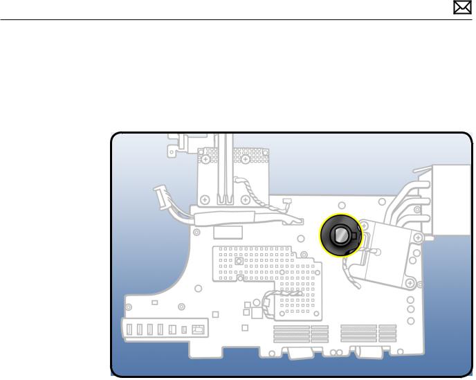
Removing the Battery, Measuring DC Voltage
1.Unplug the computer. Allow several minutes for power supply to discharge.
2.Remove logic board.
3.Remove coin battery for 1-2 minutes.The coin battery is located on the back side of the logic board (see graphic below).
4.Measure DC voltage on battery touching battery with red probe, and grounding with black probe. If voltage is 2.7v or less, replace battery.
5.Reinstall the battery and logic board.This will reset the logic board.
6.Power on computer.
7.If computer boots, check for and install all software and firmware updates.
2010-09-09 |
iMac (27-inch, Mid 2010) — General Troubleshooting 24 |

Diagnostics
The following diagnostics are required for this product:
•Apple Service Diagnostic (ASD), version 3S140
•For iMac (27-inch, Mid 2010):Apple Hardware Test (AHT), version 3A202
•Bluetooth Service Diagnostic (BSD) 1.1
Sensors Errors
Run latest available service utilities to determine if any thermal sensors or blowers are malfunctioning.When a test reports an error, reseat appropriate connections and check that all air flows are free from obstruction. If issue persists, replace the corresponding part (sensor, blower, logic board, video card, or power supply). See chart below for correlation between affected sensor, sensor location, and additional checks to perform.
Note:AHT can be run by pressing the D key on startup (if hard drive was not reformatted, or if adequate system specific restore DVD is inserted). If a sensor error is detected, AHT will report an error code containing the affected sensor name (ex:“4SNS/1/40000000 TC0H”error code reports to sensor TC0H).
Sensor |
Suspected part and Location |
Suggested Action |
Notes |
|
|
|
|
TA0P |
Excessive incoming Ambient air |
Verify that incoming/outgoing air vents |
All fans ramp at full |
|
temperature, or Ambient temp |
are free from obstruction , that sensor |
speed if sensor is |
|
sensor damaged/disconnected |
cable is securely connected to the top |
disconnected. |
|
from logic board. |
edge of the logic board and attached to |
|
|
|
the left speaker housing. Replace sensor |
|
|
|
cable if damaged. |
|
T00p |
Excessive Optical Drive area |
Verify sensor cable is securely connected |
The ODD fan will run |
|
temperature, or ODD temp |
to the logic board and the sensor |
at full speed if sensor is |
|
sensor damaged/ disconnected |
is properly attached to the ODD |
disconnected. |
|
from logic board. |
mechanism. Replace sensor cable if |
|
|
|
damaged. |
|
TH00 |
Excessive Hard Drive area |
Verify sensor cable is securely connected |
The HD fan may run at |
|
temperature, or HDD temp |
to top left side of logic board and it’s |
full speed if the sensor |
|
sensor damaged/disconnected |
connected to hard drive. Check for |
is disconnected. |
|
from logic board. Use the |
damaged cable on logic board. |
|
|
correct sensor cable, each drive |
|
|
|
vendor has a unique sensor |
|
|
|
cable model. |
|
|
Tm0p |
Excessive logic board |
Test with known-good logic board |
|
|
temperature (this sensor is part |
|
|
|
of logic board) |
|
|
|
|
|
|
TL0p |
Excessive LCD panel area |
Verify that the LCD sensor cable is |
The CPU fan will run at |
|
temperature, or LCD temp |
securely connected to the logic board |
full speed if the sensor |
|
sensor damaged/disconnected |
and the sensor is attached to the LCD. |
is disconnected. |
|
from top of logic board |
Replace the sensor cable if damaged |
|
|
|
|
|
2010-09-09 |
iMac (27-inch, Mid 2010) — General Troubleshooting 25 |

TS2P |
Excessive upper internal |
Verify that the skin temp sensor cable |
|
|
enclosure temperature, or |
is securely connected to the top of the |
|
|
Skin temp sensor damaged/ |
logic board and sensor is attached to |
|
|
disconnected from top of logic |
rear housing (near the camera). Replace |
|
|
board. |
the sensor cable if damaged. |
|
|
|
|
|
TC0H |
Excessive processor heatsink |
Check CPU sensor cable connection to |
If the sensor is |
|
temperature, or CPU temp |
logic board. It requires removal of the |
disconnected, the |
|
sensor damaged/disconnected |
logic board. |
CPU fan will run at full |
|
from back side of logic board |
|
speed. |
|
(this sensor is part of logic |
|
|
|
board) |
|
|
|
|
|
|
TG0D |
Excessive graphics processor |
Test with known-good video card |
|
|
die temperature (this sensor |
|
|
|
is part of graphics processor |
|
|
|
chip) |
|
|
TG0H |
Excessive graphics processor |
Check GPU sensor cable connection to |
If sensor is |
|
heatsink temperature, or |
logic board. It requires removal of the |
disconnected the CPU |
|
GPU temp sensor damaged/ |
logic board. |
fan will run at full |
|
disconnected from back side of |
|
speed. |
|
logic board (this sensor is part |
|
|
|
of video card assembly) |
|
|
Tp1P,Tp2H, |
Excessive power supply |
Test with known-good power cable |
|
Tp3H |
temperature (these sensors |
harness , or known-good power supply |
|
|
are part of the power supply |
board. |
|
|
board) |
|
|
ODD fan |
Optical fan/blower located |
Verify that the ODD blower/fan cable is |
Normal fan operation, |
|
next to right speaker |
securely connected to the right side of |
except the ODD blower |
|
|
the logic board and that there are no |
|
|
|
obstructions that would prevent the |
|
|
|
blower/fan from rotating. Replace fan if |
|
|
|
the error continues. |
|
HDD fan |
Hard drive fan/blower, located |
Verify that the HDD blower/fan cable |
Normal fan operation, |
|
below logic board, near hard |
is securely connected to the top of |
except the HDD blower |
|
drive |
the logic board and that there are no |
|
|
|
obstructions that would prevent the |
|
|
|
blower/fan from rotating. Replace fan if |
|
|
|
the error continues. |
|
CPU fan |
CPU fan/blower, located next |
Verify that the CPU blower/fan cable is |
Normal fan operation, |
|
to left speaker (logic board has |
securely connected to the left side of |
except the CPU blower |
|
to be removed to replace CPU |
the logic board and that there are no |
|
|
blower) |
obstructions that would prevent the |
|
|
|
blower/fan from rotating. Replace fan if |
|
|
|
the error continues. |
|
2010-09-09 |
iMac (27-inch, Mid 2010) — General Troubleshooting 26 |
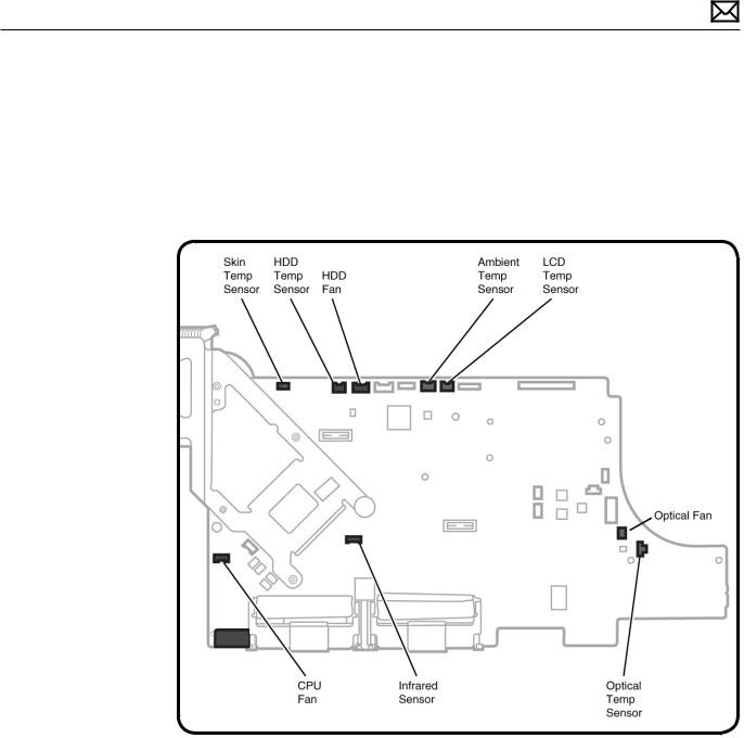
Sensor Locations
Temp sensors and fan connector locations are shown in the next two graphics. Ensure cables are correctly routed and the sensors and fans are properly connected. If a sensor or fan is faulty or not connected, Apple Hardware Test will generate an error code.
Sensor Connector Locations:Top Side of Logic Board
2010-09-09 |
iMac (27-inch, Mid 2010) — General Troubleshooting 27 |
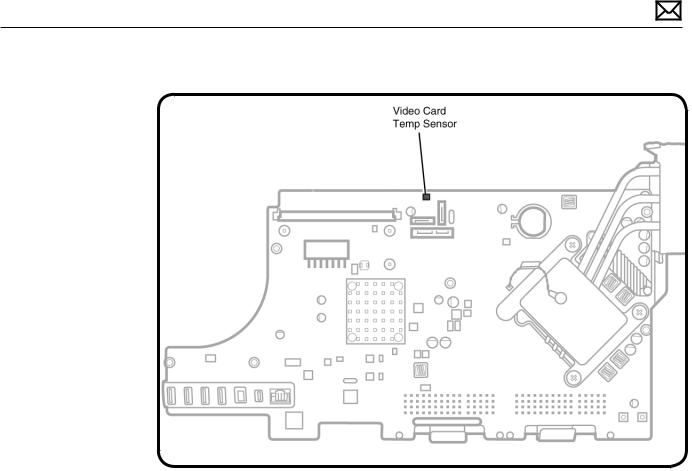
Sensor Connector Location: Back Side of Logic Board
2010-09-09 |
iMac (27-inch, Mid 2010) — General Troubleshooting 28 |
Diagnostic LEDs
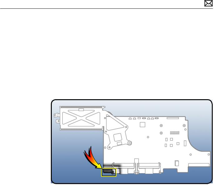
The iMac (27-inch, Mid 2010) computer has four built-in diagnostic LEDs on the main logic board that can help you to troubleshoot the computer.The LEDs are located on the bottom left edge of the logic board (under a piece of black mylar tape) and can only be seen when looking through the lower vents of the enclosure. Refer to the next page for a close up graphic of the troubleshooting LEDs.
Location of Diagnostic LEDs
The LEDs are located under the mylar tape, on the bottom, left corner of the logic board.They can only be seen when looking through lower vents of rear housing
2010-09-09 |
iMac (27-inch, Mid 2010) — General Troubleshooting 29 |
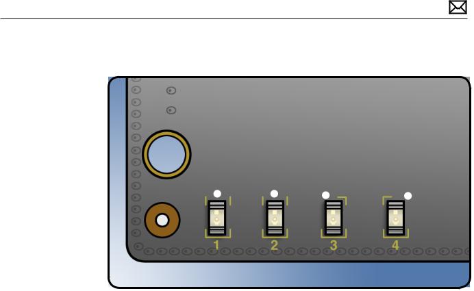
LED Functions
LED #1
•Indicates that trickle voltage from power supply has been detected by logic board.This LED will remain ON whenever the iMac is connected to a working AC power source.The LED will remain ON even when computer has been shut down or put to sleep.The LED will remain OFF only if the AC power source is missing or disconnected , if the logic board is disconnected from the power supply, or if the power supply board is faulty.
LED #2
•Indicates that the main logic board has detected proper power from the power supply when the computer is turned on and that logic board voltage regulators are functioning properly.This LED will be ON when the computer is turned on and the power supply should be working correctly.
LED #3
•Indicates that the computer and the video card are communicating.This LED will be ON when the computer is communicating properly with the video card. If LEDs 1 and 2 are ON and you heard the startup sound, but LED 3 is OFF, then the video card might be installed incorrectly or need replacement.
LED #4
•Indicates that the computer and the LCD panel are communicating.This LED will be ON when the computer is turned on and video signal is being generated. If the LED is ON and there is no image on the display, then the LCD panel, the LED backlight board, or the cables between might be installed incorrectly or need replacement.
2010-09-09 |
iMac (27-inch, Mid 2010) — General Troubleshooting 30 |
Loading...