


Highres Monochrome Monitor
Table of contents
 Loading...
K
Service Source
Apple High-Res
Monochrome Monitor
K
Service Source
Specifications
Apple High-Resolution
Monochrome Monitor

Specifications Characteristics - 1
Characteristics
Picture Tube
Screen Resolution
Scan Rates
Active V ideo Display Area
12-in. diagonal screen
Phosphor EIA Type P4 (white)
Flat, high-contrast, antiglare surface
640x480; 76 dpi
Vertical refresh rate: 66.7 Hz
Horizontal scan rate: 35.0 kHz
8.38 in. by 6.3 in. (213 mm by 160 mm)

Specifications Characteristics - 2
Input Signal
Video: analog; RS-343 standard

Specifications Controls - 3
Controls
User Controls
Rear panel: power switch
Right side: brightness and contrast controls

Specifications Physical and Electrical - 4
Physical and Electrical
Power Supply
Size and Weight
Universal power supply
Voltage: 85–270 VAC
Frequency: 50–60 Hz
Power: 40 W maximum
Height: 10 in. (254 mm)
Width: 12.2 in. (310 mm)
Depth: 14.4 in. (365 mm)
Weight: 17 lb. (7.7 kg)

Specifications Operating Environment - 5
Operating Environment
Temperature
Humidity
Altitude
50°C–l04°F (l0°C–40°C)
90% maximum, noncondensing
10,000 ft. (3,048 m) maximum

K
Service Source
Troubleshooting
Apple High-Resolution
Monochrome Monitor

Troubleshooting General/ - 1
General
The Symptom Charts included in this chapter will help you
diagnose specific symptoms related to your product. Because cures
are listed on the charts in the order of most likely solution, try
the first cure first. Verify whether or not the product continues to
exhibit the symptom. If the symptom persists, try the next cure.
(Note: If you have replaced a module, reinstall the original module
before you proceed to the next cure.)
If you are not sure what the problem is, or if the Symptom Charts
do not resolve the problem, refer to the Flowchart for the product
family.
For additional assistance, contact Apple Technical Support.

Troubleshooting Symptom Charts/No Raster - 2
Symptom Charts
No Raster
No raster, LED off 1 Ensure monitor’s video cable is connected to the computer or
the video card in the computer.
2 Verify that power cord is connected.
3 Check internal power connectors.
4 Replace fuse.
5 Replace power supply.
6 Replace power switch.
No raster, LED on 1 Ensure monitor’s video cable is connected to the computer or
the video card in the computer.
2 Adjust brightness and contrast knobs.
3 Replace video card (if present) in computer.
4 Adjust sub-brightness (cutoff) control.
5 Check logic board connection to power supply.
6 Replace fuse.
7 Replace main board.
8 Replace power supply.
9 Replace power switch assembly.
10 Replace video board C.
11 Replace contrast control board.

Troubleshooting Symptom Charts/Geometry - 3
Geometry
Raster stretched or
compressed on side or
top of screen
1 Verify that distortion is not due to environmental conditions.
2 Perform appropriate geometric adjustments.
3 Replace main board.
4 Replace CRT.

Troubleshooting Symptom Charts/Synchronization - 4
Synchronization
Picture breaks into
diagonal lines
Picture rolls
vertically
One horizontal or
vertical line appears
on screen
1 Connect another monitor to computer and verify presence of
video signal.
2 Replace main board.
1 Verify that video card in computer is working properly.
2 Adjust vertical hold.
3 Check connector on I/O connector board.
4 Replace main board.
1 Check yoke connectors.
2 Replace main board.
3 Replace CRT.

Troubleshooting Symptom Charts/Video - 5
Video
Picture too dark or
too bright
Brightness
unadjustable
Out of focus 1 Perform focus adjustments.
1 Adjust brightness knob.
2 Verify that video card in computer is working properly.
3 Adjust sub-brightness (cutoff) control.
4 Replace main board.
5 Replace video board C.
6 Replace CRT.
1 Replace contrast control board.
2 Replace main board.
3 Replace video board C.
4 Replace CRT.
2 Replace main board.
3 Replace video board C.
4 Replace CRT.

Troubleshooting Symptom Charts/Miscellaneous - 6
Miscellaneous
Picture jitters 1 Check grounding cable connections to chassis.
2 Confirm that adjacent computer equipment is properly
grounded. Move electrical devices away from monitor.
Temporarily shut off fluorescent lights in area.
3 Replace main board.
Flashing lines on
screen
Black spots on screen
(burnt phosphors)
1 Confirm contact of video connector to neck of CRT.
2 Replace contrast control board.
3 Replace main board.
Replace CRT.
K
Service Source
T ak e Apart
Apple High-Resolution
Monochrome Monitor
Take Apart Rear Cover - 1
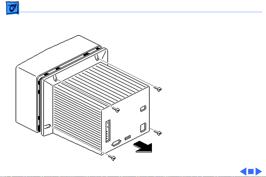
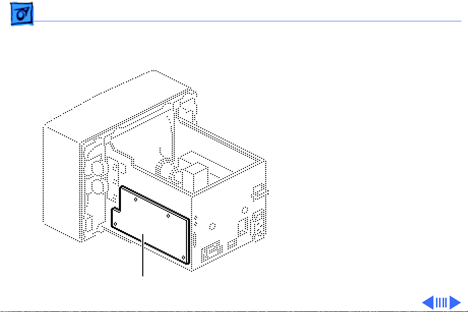
Rear Cover
No preliminary steps are
required before you begin
this procedure.
Remove the four case screws
and lift off the rear cover.
Take Apart Main Board - 2
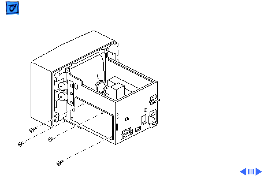
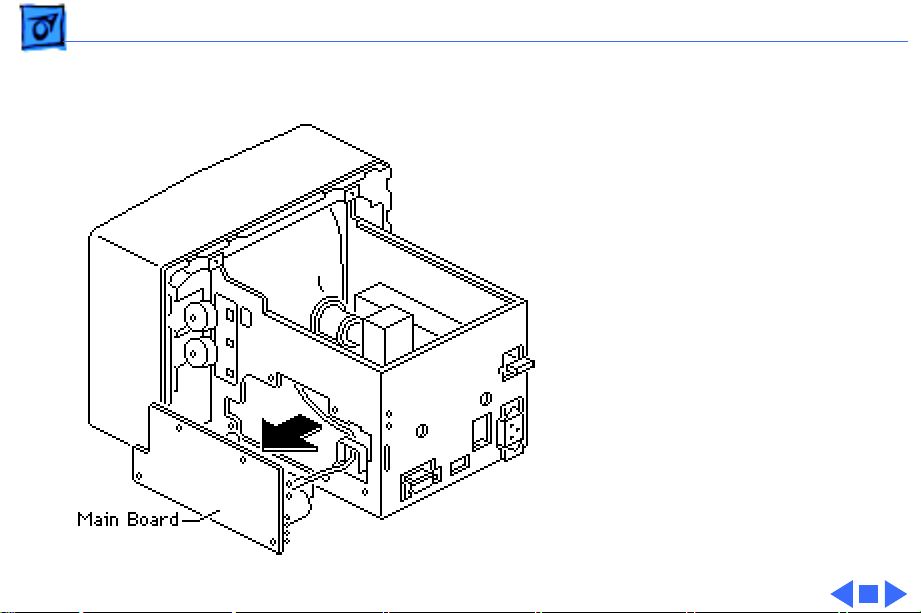
Main Board
Before you begin:
• Remove the rear cover
• Discharge the CRT
±
Main Board
Warning:
contains high voltage and a
high-vacuum picture tube.
To prevent serious injury,
review CRT safety in
Bulletins/Safety.
±
Warning:
grounding wriststrap until
after discharging the CRT.
This product
Never use a
Take Apart Main Board - 3
1 Remove the four screws
that fasten the main
board to the chassis.
Take Apart Main Board - 4
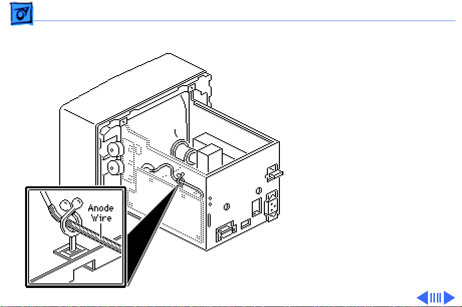
2 Remove the anode wire
from the cable clamp.
Take Apart Main Board - 5
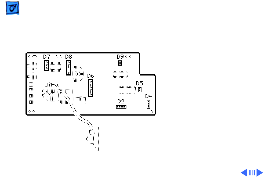
Note:
Connectors D2, D4,
D5, and D9 fit tightly and
are difficult to reach, so
pull the main board away
from the chassis before you
try to remove these
connectors.
3 Remove the following
cable connectors from
the main board:
• D7 (large 3-pin
connector)
• D8 (large 4-pin
connector)
• D6 (large 6-pin
connector)
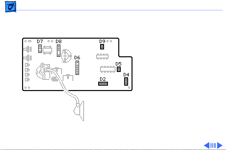
Take Apart Main Board - 6
• D9 (2-pin connector)
• D2 (5-pin connector)
• D5 (2-pin connector)
• D4 (4-pin connector)
Take Apart Main Board - 7
4 Lift the main board
from the chassis.
Loading...