


 Loading...
Service Source
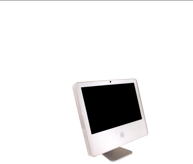
iMac (20-inch Late 2006)
13 December 2007
© 2006 Apple Inc. All rights reserved.

iMac (20-inch Late 2006)
Contents
Take Apart
General Information 6
Product View 6 |
|
|
||
Serial Number Location |
7 |
|||
Tools Required 9 |
|
|
||
Safety |
10 |
|
|
|
Access Tool Modification |
11 |
|||
What’s New |
17 |
|
|
|
Access Door |
19 |
|
|
|
Front Bezel 21 |
|
|
||
Camera Board 29 |
|
|
||
Lower EMI Shield |
35 |
|
||
IR Board |
38 |
|
|
|
Battery |
43 |
|
|
|
LCD Display Panel |
45 |
|
||
Memory |
52 |
|
|
|
Speakers |
56 |
|
|
|
AirPort Extreme Card 60 |
||||
Bluetooth Card 65 |
|
|
||
Optical Drive |
68 |
|
|
|
Hard Drive 76 |
|
|
||
Power Supply |
83 |
|
|
|
Logic Board |
89 |
|
|
|
AC Power Inlet 99
ii

Fan, Hard Drive 103 |
|
Fan, Optical Drive |
107 |
Fan, CPU 110 |
|
Inverter 113 |
|
Ambient Light Sensor Board 117 |
|
Cable, Camera and IR 120 |
|
Bluetooth Antenna |
123 |
AirPort Antennas |
127 |
Clutch Mechanism |
131 |
Chassis 135 |
|
Rear Housing 139 |
|
Stand 142 |
|
Cable, AC/DC SATA, Inverter Power 146 |
|
Troubleshooting
General Information 151
Symptom Charts 156
How to Use the Symptom Charts 156
Power Issues |
157 |
||
No Video |
158 |
|
|
Video Distortion After Waking From Sleep 160 |
|||
Display |
163 |
|
|
Optical Drive |
167 |
||
Fan Sound |
172 |
||
AirPort |
176 |
|
|
Bluetooth |
177 |
||
IR Remote |
178 |
||
IR Sensor/Receiver 179 |
|||
Built-in iSight Camera 180 |
|||
Speakers |
182 |
|
|
Mouse |
183 |
|
|
Keyboard |
184 |
||
Error Beep(s) |
185 |
||
USB 186 |
|
|
|
iii

Views
iMac (20-inch Late 2006)—Upper Exploded View |
188 |
iMac (20-inch Late 2006)—Lower Exploded View |
189 |
Screw Chart 190
Screw Chart : iMac (20-inch Late 2006): page 1 190
iv

Service Source
Take Apart
iMac (20-inch Late 2006)
© 2006 Apple Computer, Inc. All rights reserved.
 General Information
Product View
iMac (20-inch Late 2006) Take Apart — General Information 6
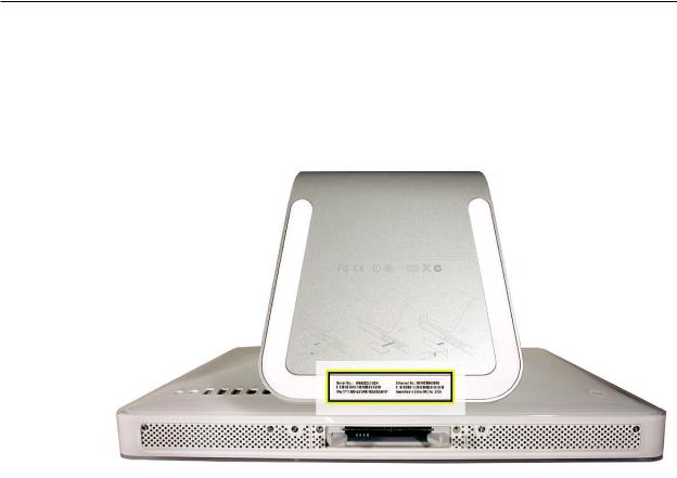
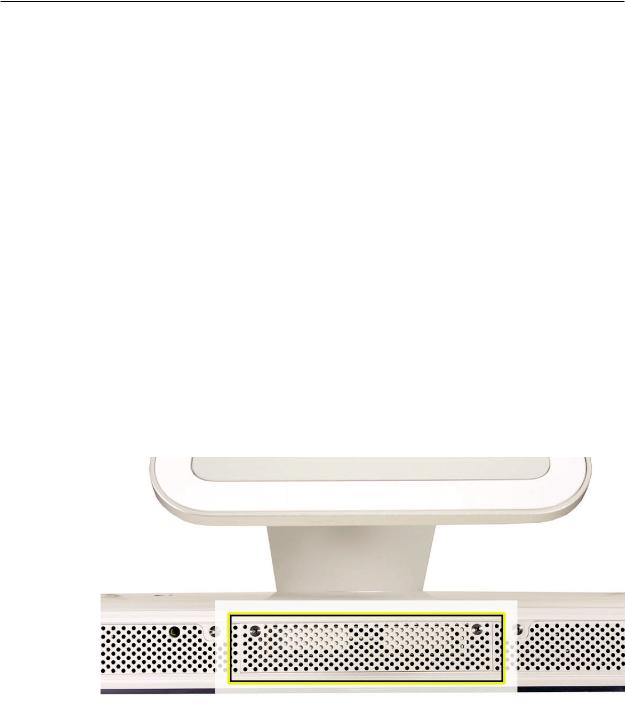
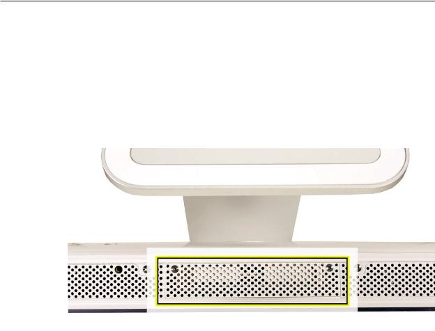
Serial Number Location
On the bottom of your iMac stand, you’ll find a label with the serial number printed on it:
Serial Number Location
iMac (20-inch Late 2006) Take Apart — General Information 7

What’s New on the iMac (20-inch Late 2006)?
Logic board
•Intel Core 2 Duo Processor running at 2.16 or 2.33 GHz
AirPort Extreme and Bluetooth antennas
•Separate antennas: Two AirPort antennas, one Bluetooth antenna
Inverter Board
•New service part, 661-4112. It serves as the flat panel backlight controller.
Camera Board
•New service module, 661-4113, is smaller than previous camera boards.
Memory
•Supports up to 3 GB system memory
•Supports two standard PC2-5300 DDR2 SO-DIMM modules
Rear cover and Front bezel
•New part numbers (922-7769 and 922-7875) with slight revisions to each part
DC-DC Board
•There is no DC/DC board. The functionality previously accomplished on the DC/DC board has been integrated into the logic board
iMac (20-inch Late 2006) Take Apart — General Information 8

Tools Required
The following tools are required to service the computer. Note that a special access card (part 9227172) is required to open the front bezel.
•ESD-safe workstation and mat
•Soft, clean towel or cloth (to protect the display and removed parts from scratches)
•Access card to open the rear cover (part 922-7172)
•Black stick (or other nonconductive nylon or plastic flat-blade tool)
•Phillips #1 screwdriver
•Phillips #2 screwdriver
•Torx T8 screwdriver (magnetized)
•Torx T6 screwdriver (magnetized)
•Torx T10 screwdriver (magnetized)
•Flat-blade screwdriver
iMac (20-inch Late 2006) Take Apart — General Information 9
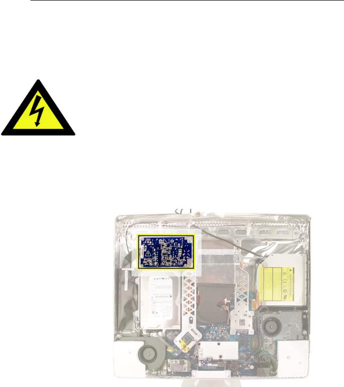
Safety
Warning: When the iMac (20-inch Late 2006) is under power, be aware that the power supply contains high voltages that pose a potential hazard to your personal safety. Never work on or near the power supply with the unit powered on, and as a further precaution always make sure the unit is unplugged when working on it with the front bezel removed.
WARNING: HIGH VOLTAGE
Text or photographs marked by this symbol indicate that a potential hazard to your personal safety exists from a high voltage source.
The AC/DC power supply board is a high voltage source with the unit under power, and remains powered up whenever the system is plugged in, whether or not the system is turned on. Use extreme caution when troubleshooting the system with the front bezel removed.
• Disconnect power to the system before performing maintenance.
• Don’t work alone. In the even of an electrical shock it is important to have another individual present who can provide assistance.
• Keep one hand in your pocket when working on any iMac (20-inch Late 2006) that is plugged in. This will help ensure that your body does not provide a path to ground in the event that you accidentally make contact with the line voltage.
• Don’t wear jewelry, watches, necklaces, or other metallic articles that could present a risk if they accidentally make contact with the power supply circuitry.
iMac (20-inch Late 2006) Take Apart — General Information 10
Opening the Computer
Apple authorized, desktop certified technicians only should ever remove the front bezel on the iMac (20-inch Late 2006). When the front bezel is removed, be sure to always ground yourself and follow ESD-safe repair practices
Removing the front bezel requires using a special access card (part 922-7172) to release latches located inside the upper corners of the front bezel. Slightly bending the upper quarter of the access tool card will help engage the latch more securely.
As you are inserting the card to disengage the latch you should squeeze the top of the bezel, that will help take pressure off of the latch and enable it to open easier. Note: If the bezel won’t open, try cutting the card lengthwise into 3/4 inch or 1.5 cm strips. Insert the card on a 45º angle, aimed toward the outer corner, and try again.
Once the card has been released it is safe to open the bezel. See the Front Bezel Take Apart procedure for more information.
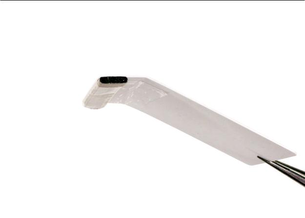
Access Tool Modification
If you wish to modify the access card tool, order kit 076-1213. The kit contains an access card and a piece of EMI gasket that can be cut and added to the top of the card. The additional thickness on the card will improve the chances of making contact with each bezel latch.
1.Remove the tape on the gasket to expose the sticky side of the gasket. Attach the sticky side of the EMI gasket to the top of the access card.
iMac (20-inch Late 2006) Take Apart — General Information 11
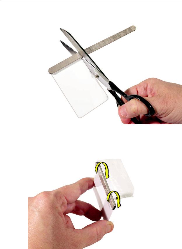
2.Cut the EMI gasket to the edge of the access card.
3.Using packing tape, or something equivalent, fold the tape over the EMI gasket to attach the gasket to the card.
iMac (20-inch Late 2006) Take Apart — General Information 12
4.Bend the card at a slight angle at the top to make sure the card makes contact with each latch.
5.Refer to Removing the Front Bezel for the complete procedure.
6.
iMac (20-inch Late 2006) Take Apart — General Information 13
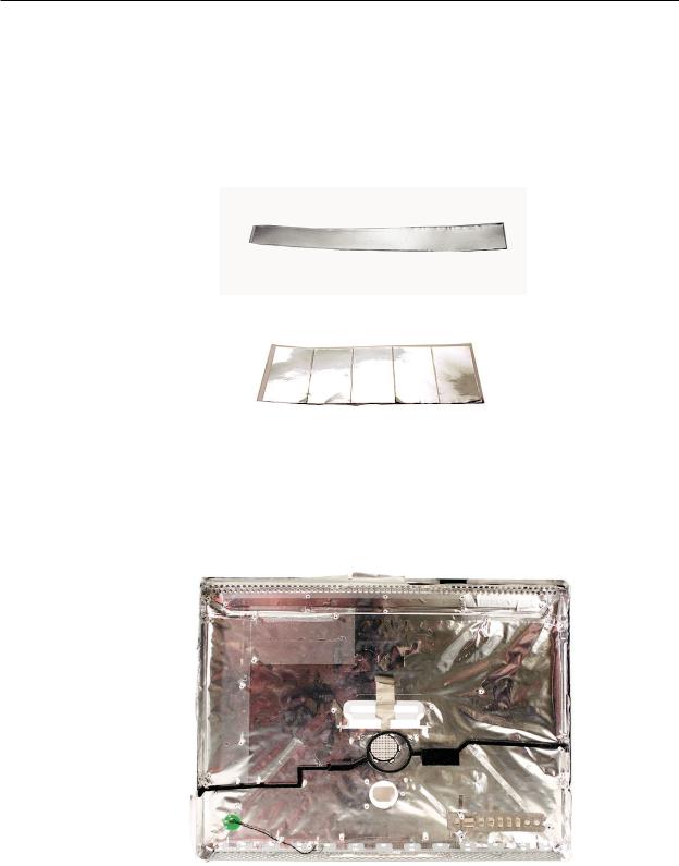
EMI Shielding
The iMac enclosure is wrapped in EMI shielding that is easily torn and damaged. To maintain a properly shielded unit, you must repair all accidental tears and cracks to the shielding by
covering them with EMI tape. Order EMI tape, part number 922-4786 (a long, thin strip) or 9225026 (short, wide strips).
Cover nicks with EMI tape. Pay particular attention to the EMI shielding inside the rear housing, shown below. The EMI shield is easily damaged when replacing modules.
•
iMac (20-inch Late 2006) Take Apart — General Information 14
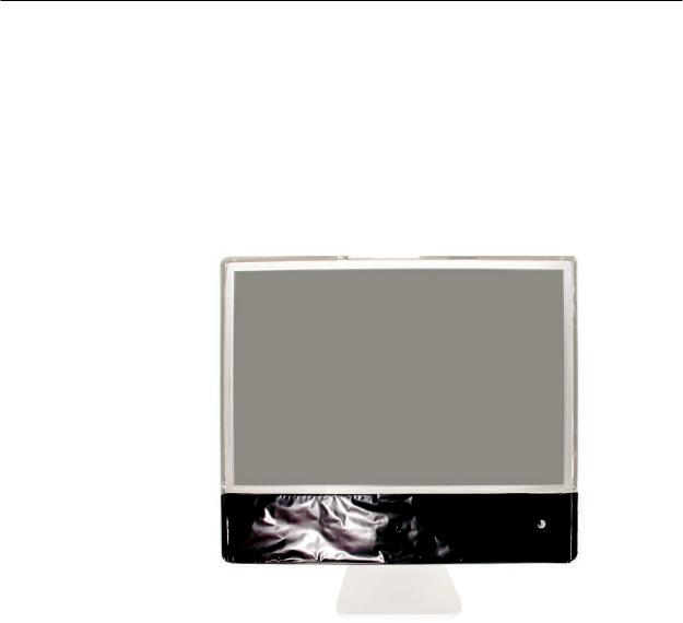
Lower EMI Shield
EMI tape covers the top and sides of the display panel, and the lower EMI shield covers the logic board along the bottom of the unit. The EMI tape and lower EMI shield are easily damaged when removed, and removal is necessary in order to access most components within the unit.
Should the EMI tape that seals the display, or the EMI shield covering the bottom of the enclosure (see photo below) accidentally tear, use the EMI tape (922-4786 or 922-5026) to repair and completely seal the unit.
iMac (20-inch Late 2006) Take Apart — General Information 15
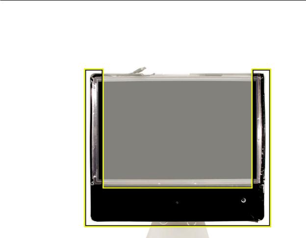
When properly repaired, all edges shown below will be wrapped by EMI tape, and the tape securely adhered to all edges. Use a “black stick” to flatten the EMI tape tightly and rub out air pockets and wrinkles.
iMac (20-inch Late 2006) Take Apart — General Information 16

 What’s New
13 December 2007
Troubleshooting---> No Video--> Symptom 2: No Video, Boot Chime Heard, White LED ON: Step 4 was corrected to reference Step 7 instead of Step 8, which does not exist.
29 October 2007
A note was added to the Logic Board Replacement section to tell service providers to install the iMac Firmware Update 1.2 (or later).
•For proper performance and reliability of the Intel Core 2 Duo processors, apply the iMac firmware update after replacing the logic board.The firmware update allows Apple service to consolidate the version 1 and version 2 logic boards.Refer to KBase article: Firmware updates for Intel-based Macs.
•The 661-4108 logic board will replaced by 661-4294
•The 661-4109 logic board will replaced by 661-4295
•The 661-4110 logic board will replaced by 661-4296
•The 661-4111 logic board will replaced by 661-4297
16 October 2007
•Corrected the Ambient Light Sensor part number on the Exploded View. diagram The correct part number is 922-7759.
23 April 2007
•The optical drive removal procedure has been updated. Using a screwdriver to release the optical drive tabs is causing damage to the logic board. The updated procedure shows how to remove the optical drive using a needlenose pliers.
•Additional information on handling slot-load optical drives can be referenced in Kbase article 305282.
22 February 2007
•Updated Upper Exploded View and created hyperlink to EEE code compatiblilty chart.
16 February 2007
•The AirPort Extreme Card and Logic Board sections in Take Apart have been updated with EEE code compatibility information. Before replacing either part, check for compatibility.
iMac (20-inch Late 2006) — What’s New 17

12 January 2007
•The “No Power” symptom in Troubleshooting has been updated. If your computer won’t turn on, try removing and reinstalling the SO-DIMMs.
4 December 2006
•Troubleshooting has been updated with a new symptom,“Display does not remain in its intended position when tilted.”
11 November 2006
•A drawing of the clutch mechanism (922-7002) was added to the Exploded View drawing.
31 October 2006
•Troubleshooting has been updated with a new symptom,“Fans running at full speed after computer turns on.” Note: The customer may have entered a diagnostic mode that causes the fans to run at full speed. This symptom is very easy to resolve at the customer level.
29 September 2006
•The inverter procedure was updated; the DC cable connection to the inverter changed.
•Photos of the EMI tape (922-44786 and 922-5026), used to repair torn and damaged EMI shielding, have been added to the EMI Shielding section in the General Information chapter
6 September 2006
•Product Introduction: iMac (20-inch Late 2006)
•Logic board: Intel Core 2 Duo processor running at 2.16 or 2.33 GHz
•AirPort Extreme and Bluetooth antennas: Two AirPort antennas, one Bluetooth antenna
•Inverter Board :New service part, 661-4112. It serves as the flat panel backlight controller.
•Camera Board: New service module, 661-4113, is smaller than previous camera boards.
•Memory: Accepts up to a 2 GB SO-DIMM in each of the two memory slots, but the iMac will only support 3 GB total memory
•Rear cover and front bezel: New part numbers (922-7769 and 922-7875) with slight revisions to each part
•DC-DC Board: There is no DC/DC board. The functionality previously accomplished on the DC/DC board has been integrated into the logic board
iMac (20-inch Late 2006) — What’s New 18
 Access Door
Tools
•Phillips #2 screwdriver
•ESD-safe workstation and mat
•Soft , clean towel or cloth
Preliminary Steps
Before you begin, lay the computer down so the panel is face down and the bottom is facing you.
Part Location
iMac (Early 2006 20-inch) Take Apart — Access Door 19
Removing the Access Door
1.Raise the stand and use a Phillips #2 screwdriver, to loosen the two captive access door screws.
Warning: The ambient light sensor is located to the left. Don’t mistake the ambient light sensor for a screw. Sticking a screw driver or other sharp object in the ambient light sensor could damage the computer.
2.Remove the access door.
Replacing the Access Door
1.Position the access door on the rear housing over the memory compartment.
2.Lift the stand out of the way.
3.Use a Phillips #2 screwdriver to tighten the captive screws.
iMac (Early 2006 20-inch) Take Apart — Access Door 20
 Front Bezel
Tools
This procedure requires the following tools:
•Torx T8 screwdriver
•Access card tool 922-7172
Preliminary Steps
Before you begin, remove the access door.
Part Location
iMac (20-inch Late 2006) Take Apart — Front Bezel 21
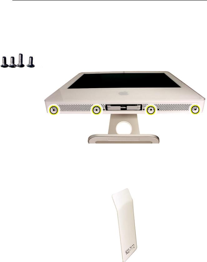
Removing the Front Bezel
1.Position unit on rear cover with the stand facing you.
2.Tilt up the front bezel and remove four screws along the bottom. The longer screw is the second screw from the right. It’s to the left of the ambient light sensor.
Warning: The ambient light sensor is located in the second hole from the right. Don’t mistake the ambient light sensor for a screw. Sticking a screwdriver or other sharp object in the ambient light sensor could damage the computer.
922-7011 (x3)
922-7749 (x1)
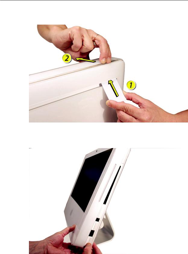
3.Locate the access card. Bending the upper quarter of the access tool card will help engage the latch. Note: Refer to AccessTool Modification in the General Information chapter if the bezel is difficult to open.
iMac (20-inch Late 2006) Take Apart — Front Bezel 22
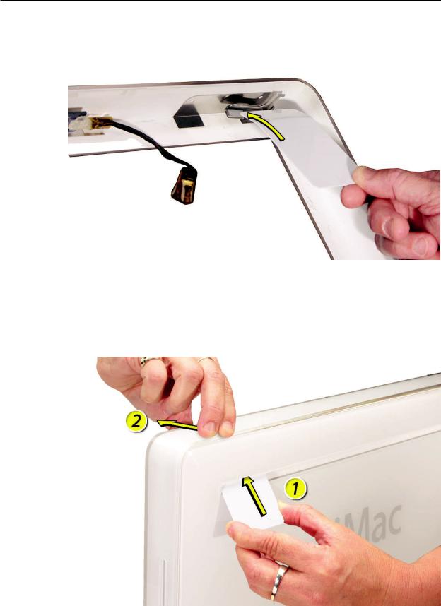
4.This picture shows how the access tool works. Pushing the tool up the vent on the rear cover releases the latches on the inside of the front bezel. Refer to the next step for the procedure.
5.Start on the left side (looking from the back of the unit). As you insert the card to disengage the latch, squeeze the top of the bezel, that will help take pressure off of the latch and enable it to open easier. As the bezel releases, pull the bezel away from the rear housing. Note: If the bezel won’t open, try cutting the card lengthwise into 3/4 inch or 1.5 cm strips. Insert the card on a 45º angle, aimed toward the outer corner, and try again.
iMac (20-inch Late 2006) Take Apart — Front Bezel 23
6.Repeat step 5 to release the locking latch in the right corner. Again, pull the bezel away as the card releases the latch.
7.If the bezel won’t release, pull the bottom of the bezel out a bit and insert the access card again.
iMac (20-inch Late 2006) Take Apart — Front Bezel 24
8.Repeat step 7 for the left side.
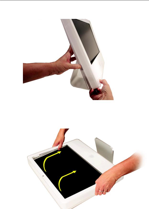
9.Once the access card has been removed, it is safe to open the bezel. Position the unit on an ESD mat, with the bottom facing toward you. Lift up the top of the bezel and pull it up and slightly toward you. Caution: Make sure the memory eject levers are not protruding from the access door when you lift the bezel up.
iMac (20-inch Late 2006) Take Apart — Front Bezel 25
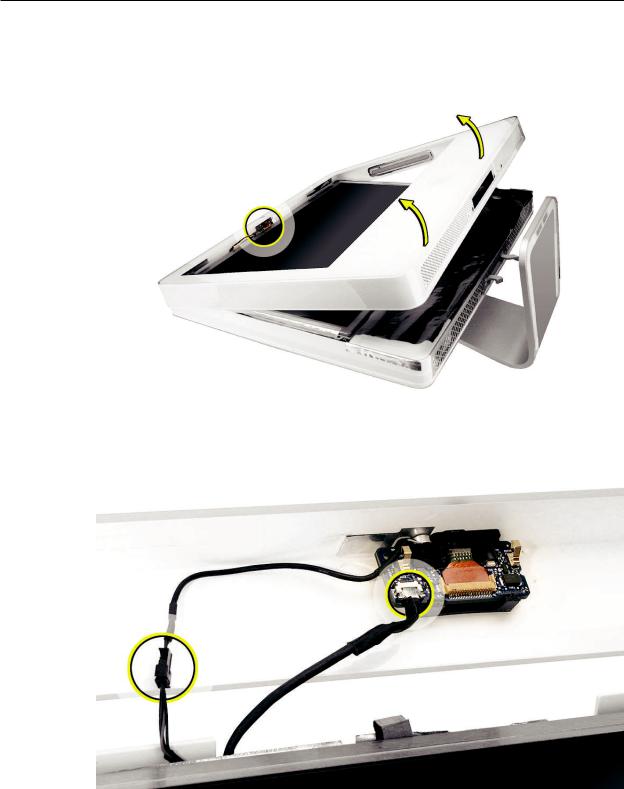
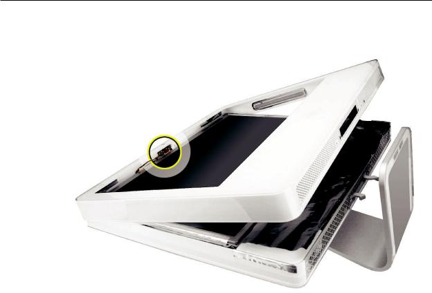
10.Swing the bezel up so you can disconnect two cables on the camera board at the top of the bezel.
11.Remove the any kapton tape and disconnect the camera and microphone cables from the camera board.
12.Lift the front bezel off the computer. If replacing a damaged front bezel, also remove the camera board. Note the microphone is part of the front bezel assembly.
iMac (20-inch Late 2006) Take Apart — Front Bezel 26
Replacing the Front Bezel
1.Make sure the black EMI shielding along the top of the LCD panel is not in the way of the locking mechanisms when you lower the front bezel onto the computer. Use a black stick to press (re-stick) the EMI shielding along the top of the panel.
2.Connect the camera and microphone cables (on the camera board) to the cables sticking out of the top of the computer.
iMac (20-inch Late 2006) Take Apart — Front Bezel 27
3.Tuck the cables neatly into the channel on the rear housing.
4.Press the memory ejector levers into the closed position.
5.Continue to lower the font bezel down and press the top corners of the front bezel to connect the latches. Note: Check that the latches are connected by lifting the front bezel at each corner.
6.Replace the four bezel mounting screws along the bottom of the computer.
7.Replace the access door; tighten the two captive screws.
iMac (20-inch Late 2006) Take Apart — Front Bezel 28
 Camera Board
Tools
•Black stick
•ESD mat, soft , clean towel or cloth
Preliminary Steps
Before you begin, remove the access door and front bezel.
Part Location
iMac (20-inch Late 2006) Take Apart — Camera Board 29

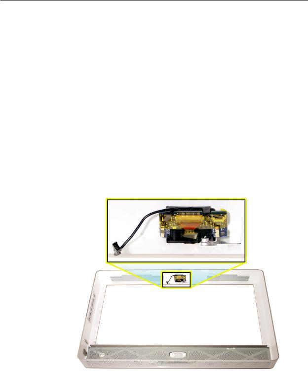
Removing the Camera Board
1.The camera board and cables are visible as you lift the front bezel off the computer.
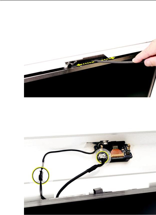
2.Remove any kapton tape on the cables. Disconnect the camera and microphone cables.
3.Remove any kapton tape covering the camera board.With your fingernail or a black stick, gently lift/flip up the flex cable locking hinge to release the flexible camera cable.
iMac (20-inch Late 2006) Take Apart — Camera Board 30
Loading...