


 Loading...
Service Source
iMac (USB 2.0)
Updated 11 September 2003
© 2003 Apple Computer, Inc. All rights reserved.

iMac (USB 2.0) |
- 1 |

Service Source
Basics
iMac (USB 2.0)
© 2003 Apple Computer, Inc. All rights reserved.

Overview
The iMac (USB 2.0) computers are powered by the PowerPC G4 processors. Two models are available: the 17-inch widescreen LCD (1.25 GHZ) or the 15-inch LCD flat screen (1 GHz). The computer also includes 80GB hard drives, 256MB DDR333 SDRAM, two FireWire 400 ports and three USB 2.0 ports. The 17-inch widescreen and the 15-inch flat panel computers come with Mac OS X version 10.2.7 installed as the default system.
How to identify these models
Verify the processor speed. If the system is up and running, select “About this Mac” under the Apple icon in the Finder. Or, select the “More Info” button on the “About this Mac” window. Apple System Profiler opens and displays the machine speed under “Hardware Overview.” The 15-inch iMac has a 1GHz PowerPC G4 processor and the 17-inch iMac has a 1.25GHz PowerPC G4 processor.
Overview |
iMac (USB 2.0) Basics - 1 |

What’s New
New Features
Processor and speed—The microprocessor in the iMac (Flat Panel, USB 2.0) is a PowerPC G4 with a clock speed of 1 GHz in the 15" configuration and a 1.25 GHz in the 17" configuration.
USB 2.0 ports— The computer has three USB 2.0 ports.
Memory— This computer comes with 256 MB of DDR333 SDRAM installed in an internal standard 186-pin DIMM expansion slot, with a build-to-order options of 512 MB. A second user-accessible slot accepts an SO-DIMM with up to 512 MB. The maximum total memory is 1 GB.
System bus— The speed of the system bus is 167 MHz.
Graphics acceleration— The AGP 4X graphics IC used is either an NVidia GeForce4MX or and NVidia GeForce FX5200 Ultra.
Video RAM— The video hardware includes either 32 MB or 64 MB of DDR SDRAM, which supports 3D features and millions of colors in all resolutions.
External video monitor— The external display connector supports mini-VGA, composite, S-video monitors and projectors, and television sets. A video adapter with composite and S-video connectors and a VGA-out adapter are available separately.
Bluetooth support (optional)— Bluetooth support is available as a build-to-order option to enable short-range wireless connections between desktop and laptop computers and a host of other peripheral devices.
2 - iMac (USB 2.0) Basics |
What’s New |

Standard Configurations
Features |
15-inch |
17-inch |
|
|
|
CPU and speed |
1GHz PowerPC G4 |
1.25GHz PowerPC G4 |
|
|
|
System bus speed |
167 MHz |
167 MHz |
|
|
|
Main memory |
256 MB SDRAM, |
256 MB SDRAM, |
|
expandable up to 1 GB |
expandable up to 1 GB |
|
|
|
Display |
15-inch flat panel |
17-inch, wide-screen flat |
|
|
panel |
|
|
|
Graphics IC |
NVIDIA GeForceMX |
NVIDIA GeForce FX |
|
|
5200 Ultra |
|
|
|
Graphics memory |
32 MB DDR RAM |
64 MB DDR RAM |
|
|
|
Hard disk drive |
80 GB Ultra ATA-66 7200 |
80 GB Ultra ATA-66 7200 |
|
rpm |
rpm |
|
|
|
Optical drive |
Tray-load Combo drive |
Tray-load SuperDrive |
|
|
|
External monitor |
Mini-VGA or S-video/ |
Mini-VGA or S-video/ |
adapter |
composite |
composite |
|
|
|
Communication fea- |
10/100 Ethernet; 56K |
10/100 Ethernet; 56K |
tures |
V.92 fax modem |
V.92 fax modem |
|
|
|
Wireless features |
Optional 54 Mbps AirPort |
Optional 54 Mbps AirPort |
|
Extreme Card; optional |
Extreme Card; optional |
|
internal Bluetooth |
internal Bluetooth |
|
|
|
What’s New |
iMac (USB 2.0) Basics - 3 |
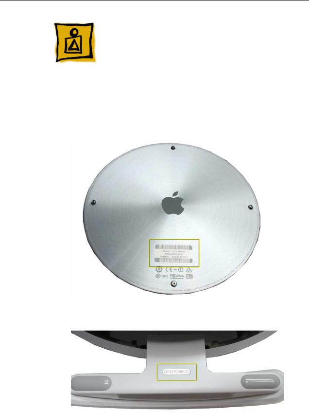
Serial Number Location
To identify a particular model of iMac (USB 2.0), check the computer’s serial number, which lists the model’s configuration. The serial number is located on the bottom of the computer, on the metal access plate, or on the inside of the optical drive door (bottom photo).
4 - iMac (USB 2.0) Basics |
Serial Number Location |

Serial Number Location |
iMac (USB 2.0) Basics - 5 |

Service Source
Take Apart
iMac (USB 2.0)
© 2003 Apple Computer, Inc. All rights reserved.

General Information
Overview
The Take Apart chapter includes take apart procedures for both the 15" and 17" iMac (USB 2.0) computers. If you are familiar with taking apart iMac (Flat Panel) computers, you will find that the procedures for these newer models haven’t changed. The changes consist of faster processors, faster system bus, larger capacity hard drives, and three USB 2.0 ports.
New Procedures
The following Take Apart sections were updated:
• Display, Inverter, Back Cover, and the Neck Assembly
Tools
The following tools are recommended for the take apart procedures.
•The service stand (076-0898)
•Thermal paste (922-4757)
•Torque driver, 17" LB (076-0899)
•1.5 mm hex driver (for LCD bezel screws)
•#0 Phillips screwdriver)
•Torx screwdriver set (6, 8, 10, 15)
•Plastic flatblade screwdriver or stylus (922-5065)
•Needlenose pliers
•ESD wriststrap and mat
General Information |
iMac (USB 2.0) Take Apart - 1 |
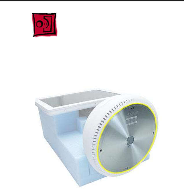
Service Stand
1.Support the computer by neck and the base (A). Gently position the computer in the service stand with the flat panel facing up (B).
2.Note: The base of the computer can be rotated when servicing internal parts.
2 - iMac (USB 2.0) Take Apart |
General Information |
User Access Plate
Tools
This procedure requires the following tools:
• Phillips #0 screwdriver
Part Location
Preliminary Steps
Before you begin, do the following:
• Position the computer in the service stand.
User Access Plate |
iMac (USB 2.0) Take Apart - 3 |
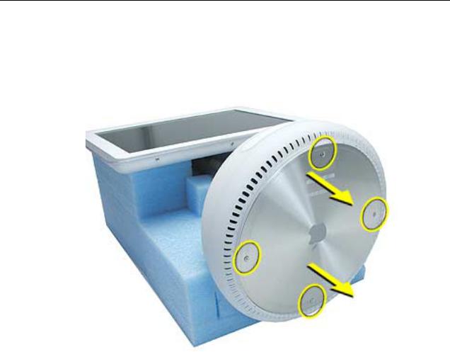
Procedure
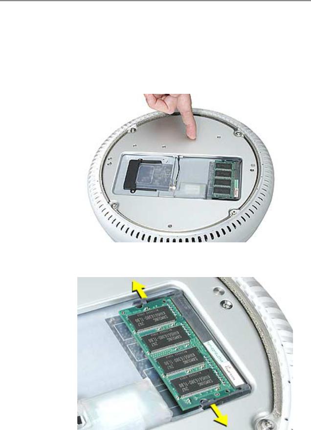
1.Loosen the four captive screws on the access panel.
2.Remove the panel by grabbing onto two captive screws and lift the panel off the base.
4 - iMac (USB 2.0) Take Apart |
User Access Plate |
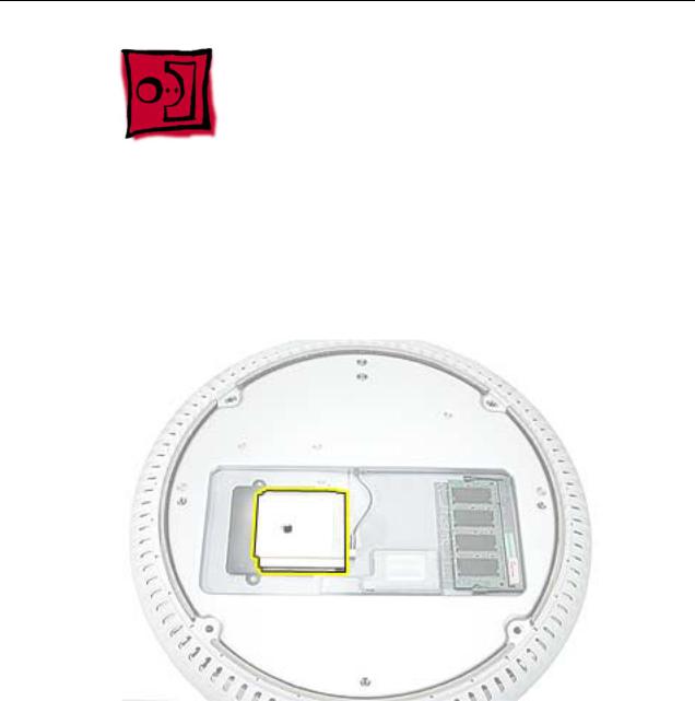
AirPort Extreme Card
Tools
This procedure requires no tools.
Part Location
Preliminary Steps
Before you begin, do the following:
•Position the computer in the service stand.
•Remove the user access plate.
AirPort Extreme Card |
iMac (USB 2.0) Take Apart - 5 |

Procedure
1.Unplug all cables from the computer except the power cord.
2.Important: To avoid electrostatic discharge, always ground yourself by touching metal before you touch any parts or install any components inside the computer. To avoid static electricity building back up in your body, do not walk around the room until you have completed the installation and closed the computer.
3.Touch a metal surface inside the computer to ground yourself.
4.Unplug the power cord.
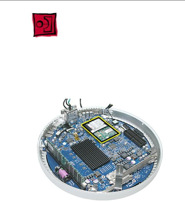
5.Pull the plastic tab on the AirPort Extreme card to remove it from the slot. Disconnect the AirPort antenna from the card.
6 - iMac (USB 2.0) Take Apart |
AirPort Extreme Card |

Memory, SO-DIMM (userinstallable)
Tools
No tools are required for this procedure.
Part Location
Preliminary Steps
Before you begin, do the following:
•Position the computer in the service stand.
•Remove the user access plate.
Note: DIMMs used in this slot should be a low-profile PC2700 (DDR333) SO-DIMM. Only the SO-DIMM slot is accessible by the user.
Memory, SO-DIMM (user-installable) |
iMac (USB 2.0) Take Apart - 7 |
Procedure
1.Unplug all cables from the computer except the power cord.
2.Important: To avoid electrostatic discharge, always ground yourself by touching metal before you touch any parts or install any components inside the computer. To avoid static electricity building back up in your body, do not walk around the room until you have completed the installation and closed the computer.
3.Touch a metal surface inside the computer to ground yourself.
4.Unplug the power cord.
5.Release the memory by spreading apart the tabs in the expansion slot from the notches in the card.
8 - iMac (USB 2.0) Take Apart |
Memory, SO-DIMM (user-installable) |

6. Allow the memory to pop up slightly, and pull it out of the memory slot.
Memory, SO-DIMM (user-installable) |
iMac (USB 2.0) Take Apart - 9 |

Bottom Housing
Tools
This procedure requires the following tools:
• Torx-15 screwdriver
Part Location
Preliminary Steps
Before you begin, do the following:
•Position the computer in the service stand.
•Remove the user access plate.
10 - iMac (USB 2.0) Take Apart |
Bottom Housing |
Procedure
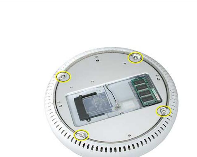
1.When opening the bottom housing, rotate the base so the optical drive door is on the right. (This position is less stressful on the internal cables when the bottom is open).
2.Remove the four torx screws.
Replacement Note: These torx screws must be tightened to at least 17 in.-lbs. If you do not have a torque driver, you will have to make sure these screws are tightened by hand FIRMLY, BUT NOT FORCIBLY. Or, purchase the service tool (076-0899) in order to ensure the thermal pipe is firmly mated with the top base. If the bottom housing is not securely attached to the base in this fashion, the CPU may overheat and become damaged. For more information, refer to “Thermal Paste Application’” in this chapter. Rotate the base so that the optical drive door is on the right.
iMac (USB 2.0) Take Apart - 11
3. Gently open the bottom housing in the direction of the arrow. Disconnect the cables.
12 - iMac (USB 2.0) Take Apart

4.Disconnect the following:
A Grounding screw
B Bluetooth connector (if Bluetooth board is present, this will be connected)
C AirPort connector
D AC line filter connector
E TMDS video connector
F Inverter, speaker, fan connector
G Optical cable and connector
H Hard drive cable and connector
I Power Supply connector
5. Set the bottom housing aside.
Warning: Whenever the bottom housing is opened for service, you must do two things:
1.You must clean the original thermal film from all thermal interface mating surfaces, and reapply thermal paste to the mating surfaces on the thermal pipe.
2. You must tighten the four torx screws on the bottom housing to a minimum of 17 in.-lbs. Use a torque driver (service tool 076-0899) to ensure that the thermal pipe is firmly mated with the top base. If you do not have a torque driver, you must make sure the screws are tightened by hand FIRMLY, BUT NOT FORCIBLY.
Failure to follow these steps could cause the computer to overheat and damage internal components.
Refer to the topic “Thermal Paste Application” for detailed information.
iMac (USB 2.0) Take Apart - 13

Thermal Paste Application
Tools
This procedure requires the following tools:
•Plastic stylus or plastic spatula to remove the old thermal paste
•Plastic stylus or plastic spatula to spread the thermal paste
•Thermal paste (922-4757)
Part Location
14 - iMac (USB 2.0) Take Apart |
Thermal Paste Application |

Procedure
1.Thoroughly clean the original thermal film from the mating surfaces (circled below) of the bottom housing and thermal pipe. Use a plastic stylus to scrape the surfaces clean. Note: Do not use an abrasive material or liquid cleaner.
2. Squeeze a ball of thermal paste onto the mating surfaces of the thermal pipe.
Thermal Paste Application |
iMac (USB 2.0) Take Apart - 15 |

3. Replace the bottom housing.
Warning: The bottom housing has four torx screws that must be tightened to at least 17 in.-lbs. Use a torque driver (service tool 076-0899) to ensure that the thermal pipe is firmly mated with the top base. If you do not have a torque driver, you must make sure the screws are tightened by hand FIRMLY, BUT NOT FORCIBLY.
Failure to apply the thermal paste as described in this procedure, and failure to tighten the torx screws as directed, could cause the computer to overheat and damage internal components.
Refer to the topic “Thermal Paste Application” for detailed information.
16 - iMac (USB 2.0) Take Apart |
Thermal Paste Application |

RJ-11 Modem Filter Board
Tools
This procedure requires the following tools:
• Torx-6 screwdriver
Part Location
Preliminary Steps
Before you begin, do the following:
•Position the computer in the service stand.
•Remove the user access plate.
•Remove the bottom housing.
RJ-11 Modem Filter Board |
iMac (USB 2.0) Take Apart - 17 |
Procedure
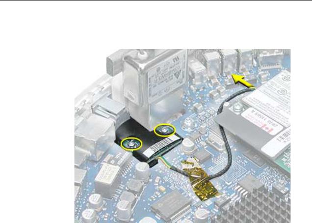
1. Remove two screws and disconnect the cable from the modem.
2. Remove the RJ-11 board from the I/O port.
Warning: Whenever the bottom housing is opened for service, you must do two things:
1.You must clean the original thermal film from all thermal interface mating surfaces, and reapply thermal paste to the mating surfaces on the thermal pipe.
2. You must tighten the four torx screws on the bottom housing to a minimum of 17 in.-lbs. Use a torque driver (service tool 076-0899) to ensure that the thermal pipe is firmly mated with the top base. If you do not have a torque driver, you must make sure the screws are tightened by hand FIRMLY, BUT NOT FORCIBLY.
Failure to follow these steps could cause the computer to overheat and damage internal components.
Refer to the topic “Thermal Paste Application” for detailed information.
18 - iMac (USB 2.0) Take Apart |
RJ-11 Modem Filter Board |
Modem
Tools
This procedure requires the following tools:
• Torx-8 screwdriver
Part Location
Preliminary Steps
Before you begin, do the following:
•Position the computer in the service stand.
•Remove the user access plate.
•Remove the bottom housing.
Modem |
iMac (USB 2.0) Take Apart - 19 |
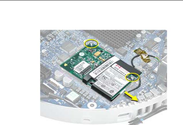
Procedure
1. Remove two screws and disconnect the cable.
2. Lift the modem board from the connector on the logic board.
Warning: Whenever the bottom housing is opened for service, you must do two things:
1.You must clean the original thermal film from all thermal interface mating surfaces, and reapply thermal paste to the mating surfaces on the thermal pipe.
2. You must tighten the four torx screws on the bottom housing to a minimum of 17 in.-lbs. Use a torque driver (service tool 076-0899) to ensure that the thermal pipe is firmly mated with the top base. If you do not have a torque driver, you must make sure the screws are tightened by hand FIRMLY, BUT NOT FORCIBLY.
Failure to follow these steps could cause the computer to overheat and damage internal components.
Refer to the topic “Thermal Paste Application” for detailed information.
20 - iMac (USB 2.0) Take Apart |
Modem |

Memory (factory-installed)
Tools
This procedure requires the following tools:
• No tools are required
Part Location
Preliminary Steps
Before you begin, do the following:
•Position the computer in the service stand.
•Remove the user access plate.
•Remove the bottom housing.
Memory (factory-installed) |
iMac (USB 2.0) Take Apart - 21 |
Loading...