


eMac (ATI Graphics) 03-07
Table of contents
 Loading...
Service Source
eMac (ATI Graphics)
Updated 15 July 2003
© 2003 Apple Computer, Inc. All rights reserved.

eMac (ATI Graphics)
eMac -
1
Service Source
Take Apart
eMac (ATI Graphics)
© 2003 Apple Computer, Inc. All rights reserved.

Tools
The following tools are recommended for the take apart procedures.
• 2.5 mm hex (for rear housing)
• Nylon probe tools (922-5065)
• Phillips #1 screwdriver
• Phillips #2 screwdriver
• Jeweler’s screwdriver set
• Needlenose pliers
• ESD wriststrap and mat
• CRT discharge tool
Note:
Do not use a power driver on the rear housing screws.
Tools
eMac (ATI Graphics) Take Apart -
1
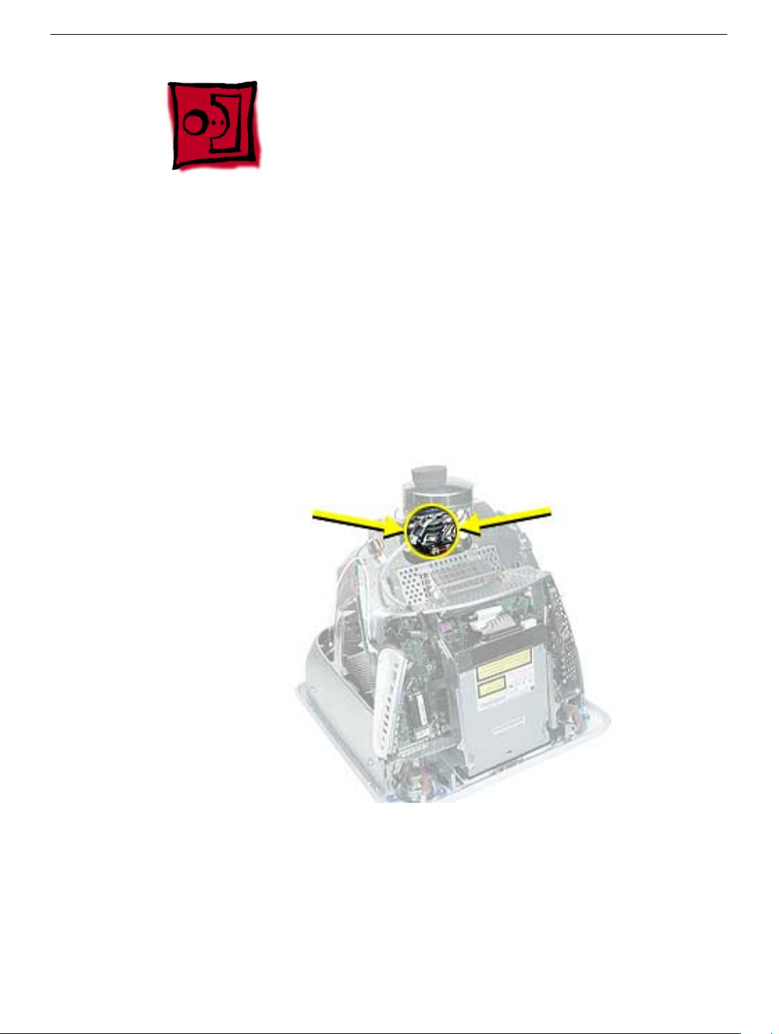
CRT Neck/Display/Analog Assembly Handling Information
Handling
Important:
when working with the display/analog assembly.
Do NOT lift, handle, bump, or manipulate the CRT neck/neck board (see arrows below) on
the Display/Analog assembly. Modules damaged by mishandling are NOT covered by
Apple Warranty. Apple Authorized Service Providers can be liable for broken CRT necks
due to improper handling.
Caution
handling the assembly. Lift the assembly from the metal chassis; never lift the assembly
from the neck. I
It is imperative that proper handling and packaging guidelines be followed
: The metal chassis has sharp edges, you may want to wear gloves when
Packing a Defective Display/Analog Assembly
The packing procedure is included with the replacement display/analog assembly.
Incorrect packaging can result in damaged eMac (ATI Graphics) displays. Please read and
follow the directions enclosed in the shipping box of the new display prior to packaging the
defective assembly. AASPs can be liable for broken CRT necks due to improper packing
and handling.
2
eMac (ATI Graphics) Take Apart
CRT Neck/Display/Analog Assembly Handling Infor-
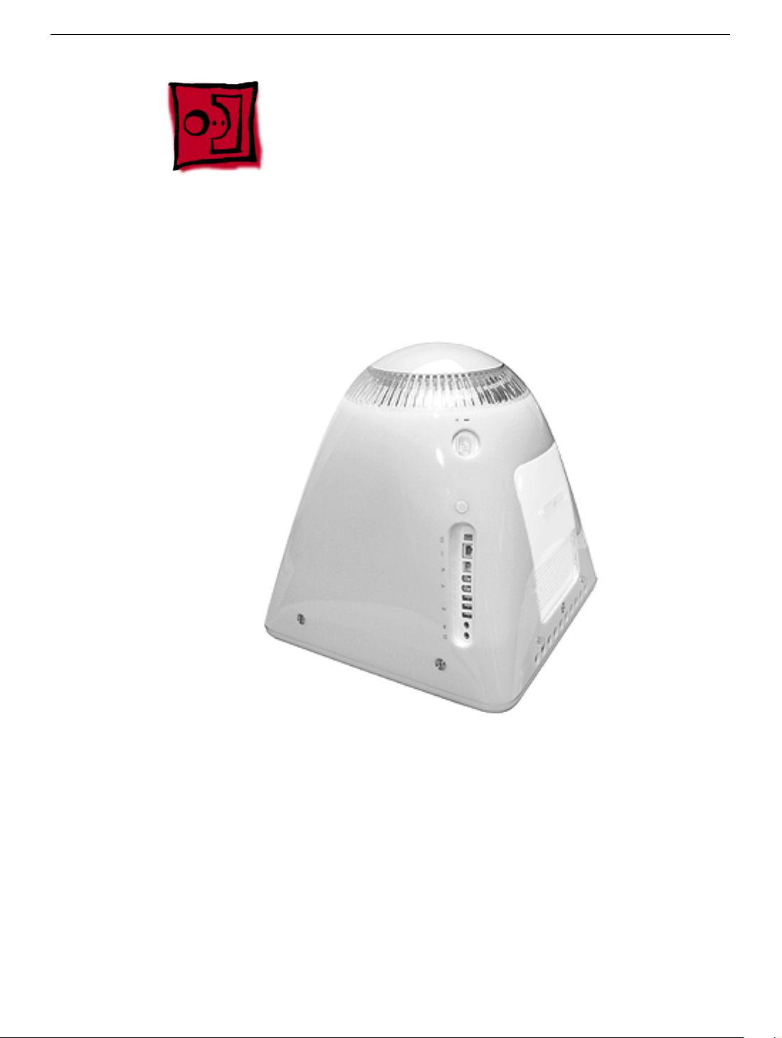
Rear Housing
Tools
• 2.5 mm hex (for the rear housing)
• Phillips #2 screwdriver
Part Location
Rear Housing
Preliminary Steps
Before you begin, do the following:
• Place the computer face down on an ESD mat.
eMac (ATI Graphics) Take Apart -
3
Procedure
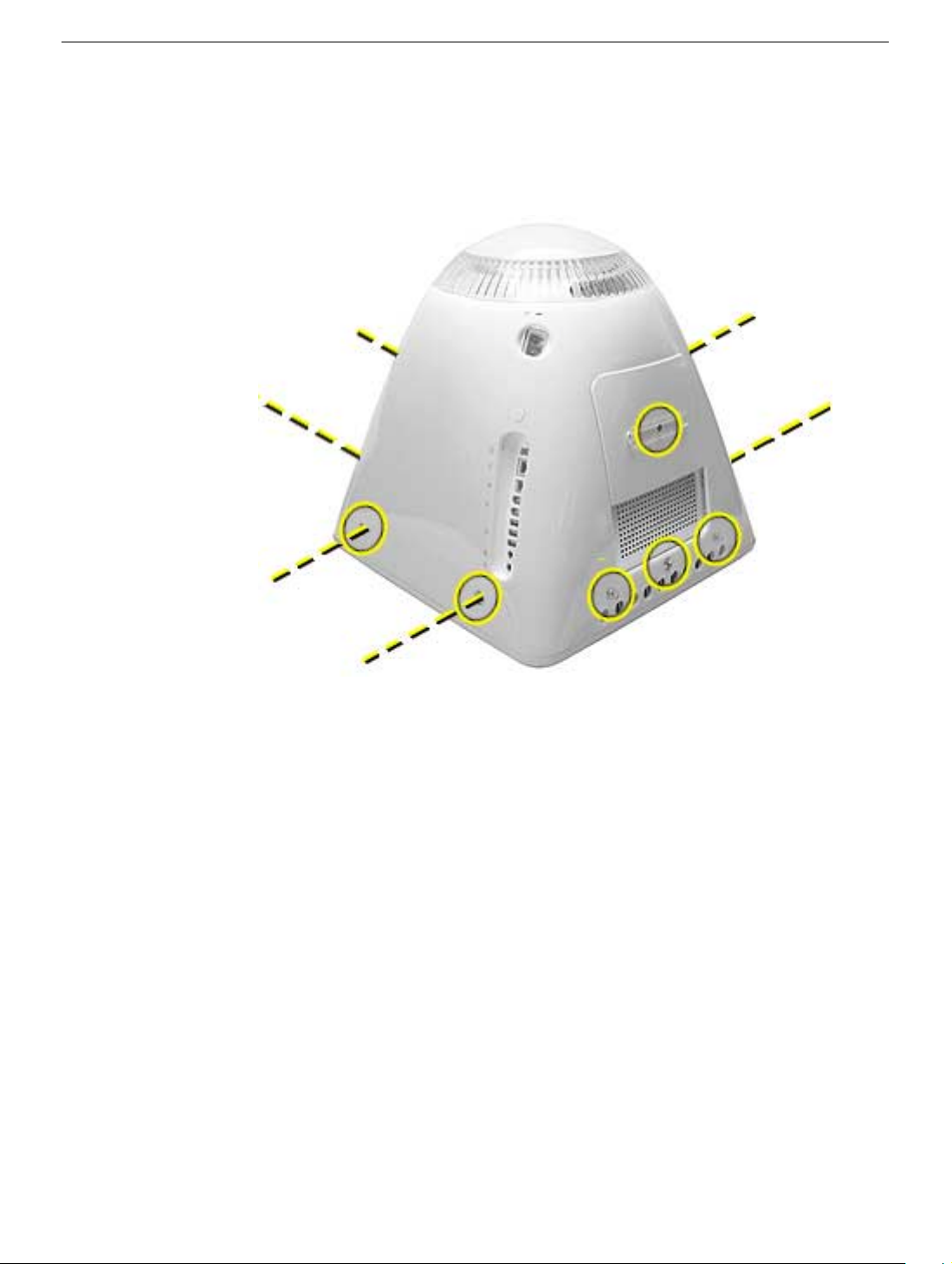
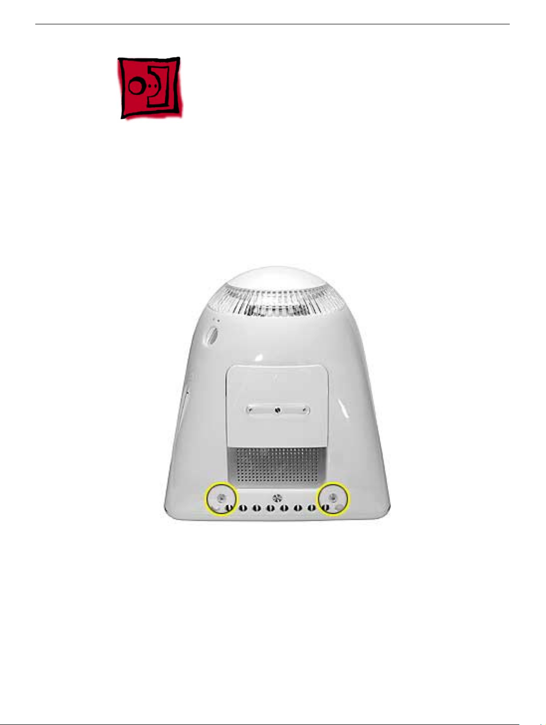
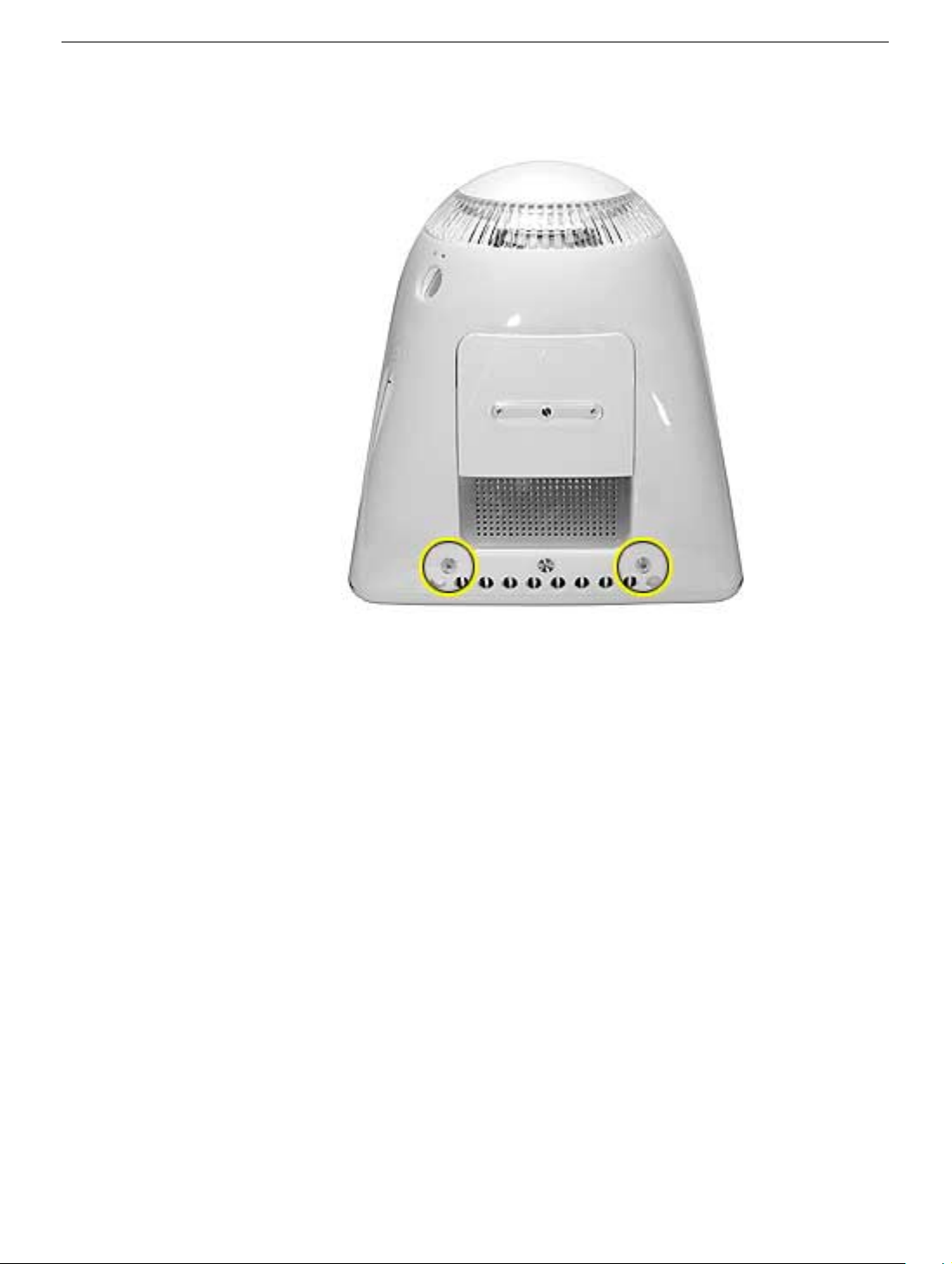
1. Remove ten screws. Seven screws on the rear housing, one screw on the user access
door (requires Phillips screwdriver), and two screws for the feet (requires Phillips
screwdriver).
4
eMac (ATI Graphics) Take Apart
Rear Housing
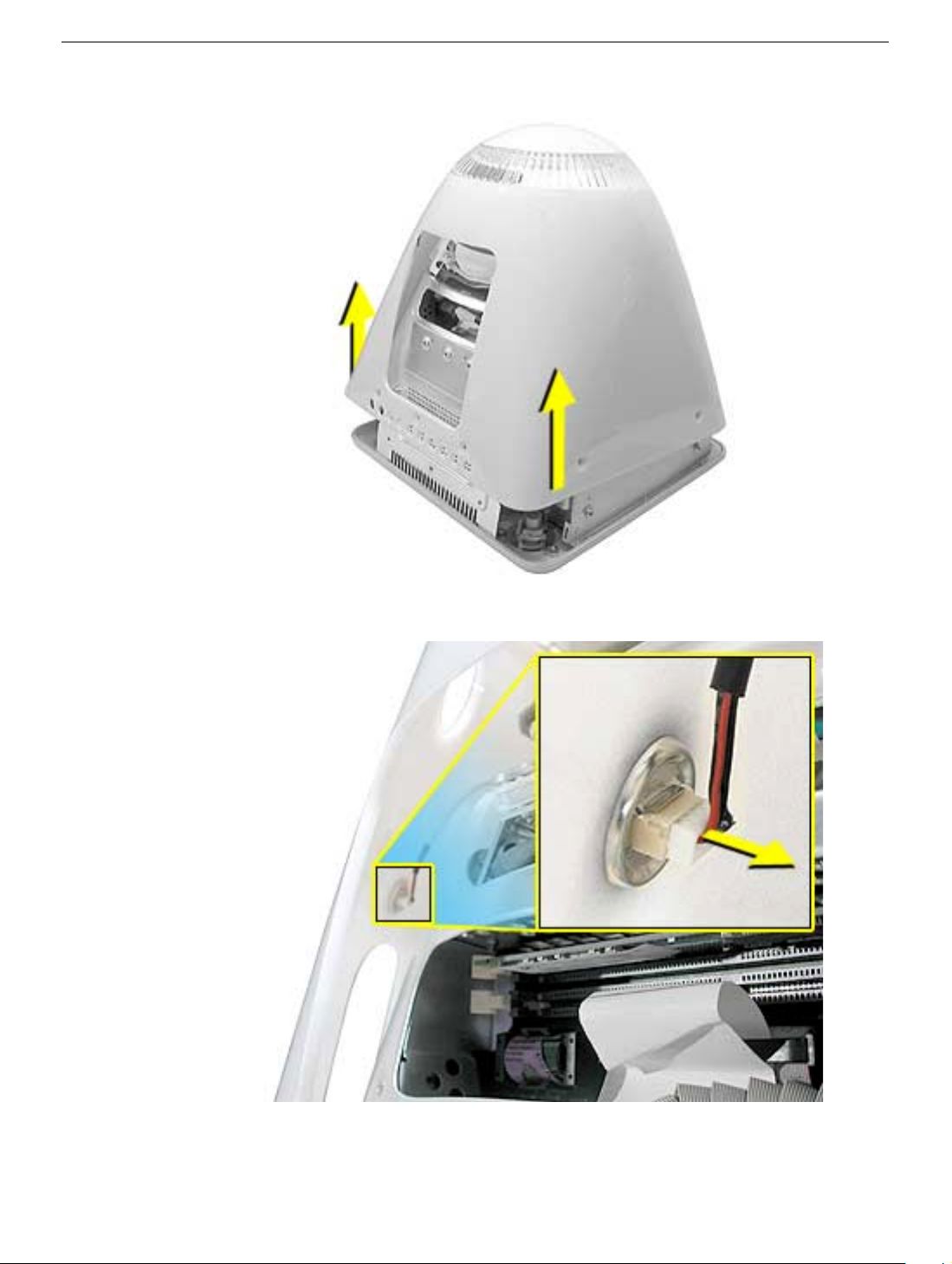
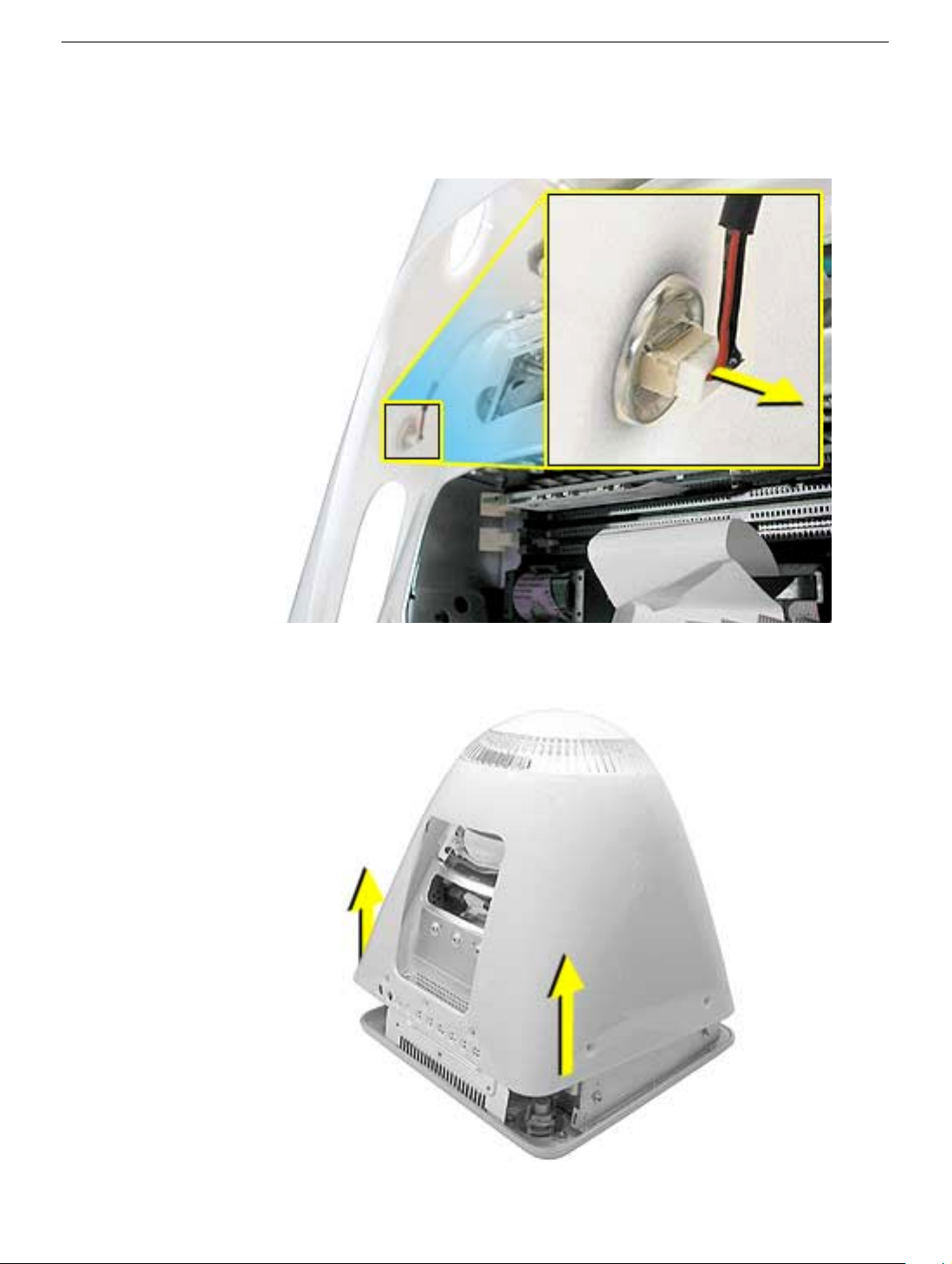
2. Gently lift the rear housing up about four inches.
3. Disconnect the power button cable located on the inside the rear housing.
Rear Housing
4. Lift the rear housing off the computer.
eMac (ATI Graphics) Take Apart -
5
User Access Door
Tools
This procedure requires the following tools:
• Phillips #2 screwdriver
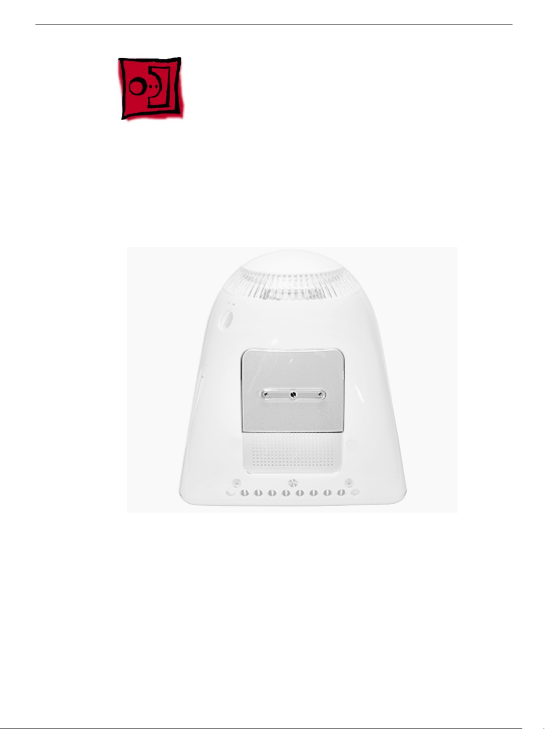
Part Location
Preliminary Steps
Before you begin, do the following:
• Place the computer face down on an ESD mat.
6
eMac (ATI Graphics) Take Apart
User Access Door
Procedure
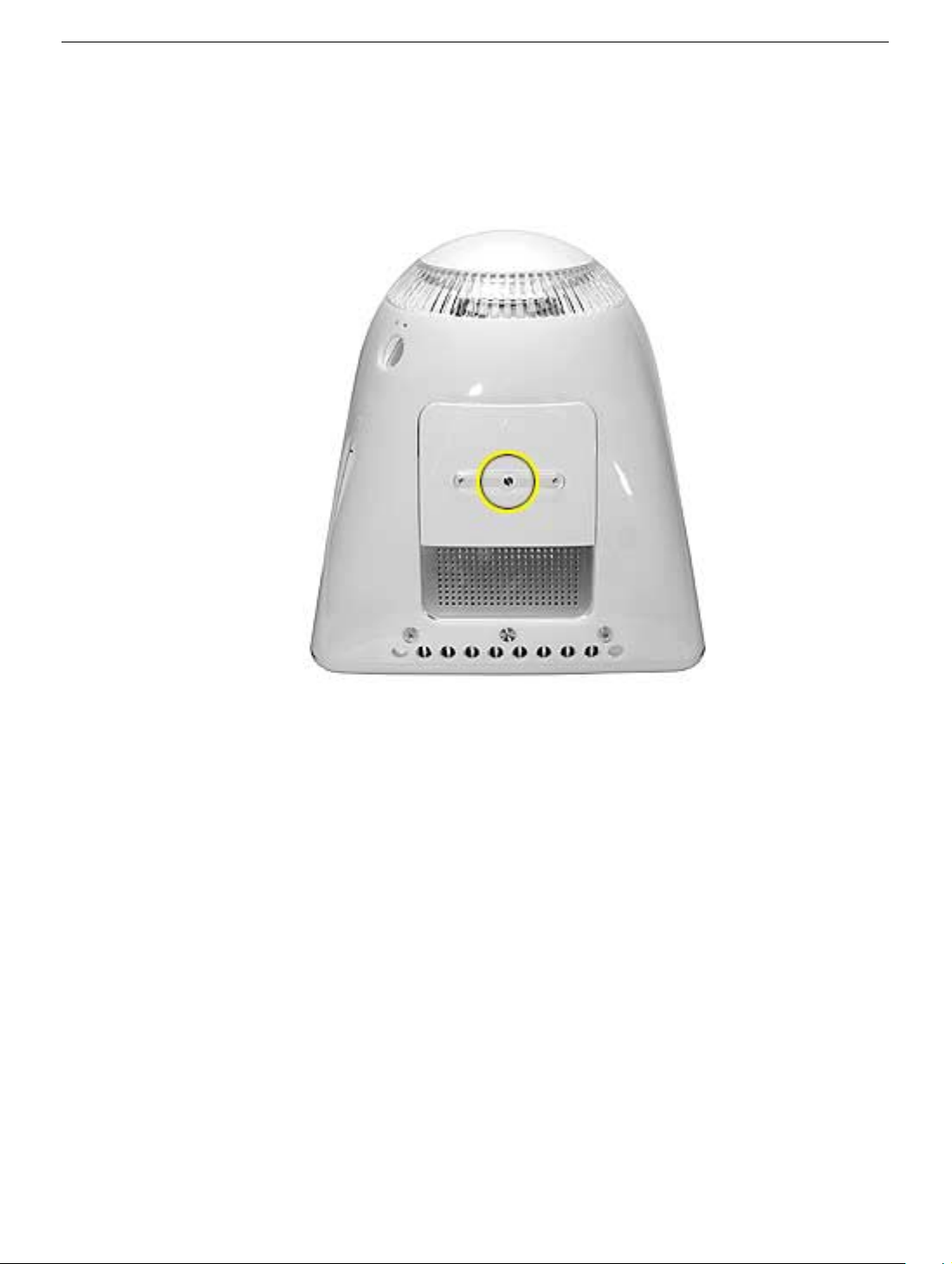
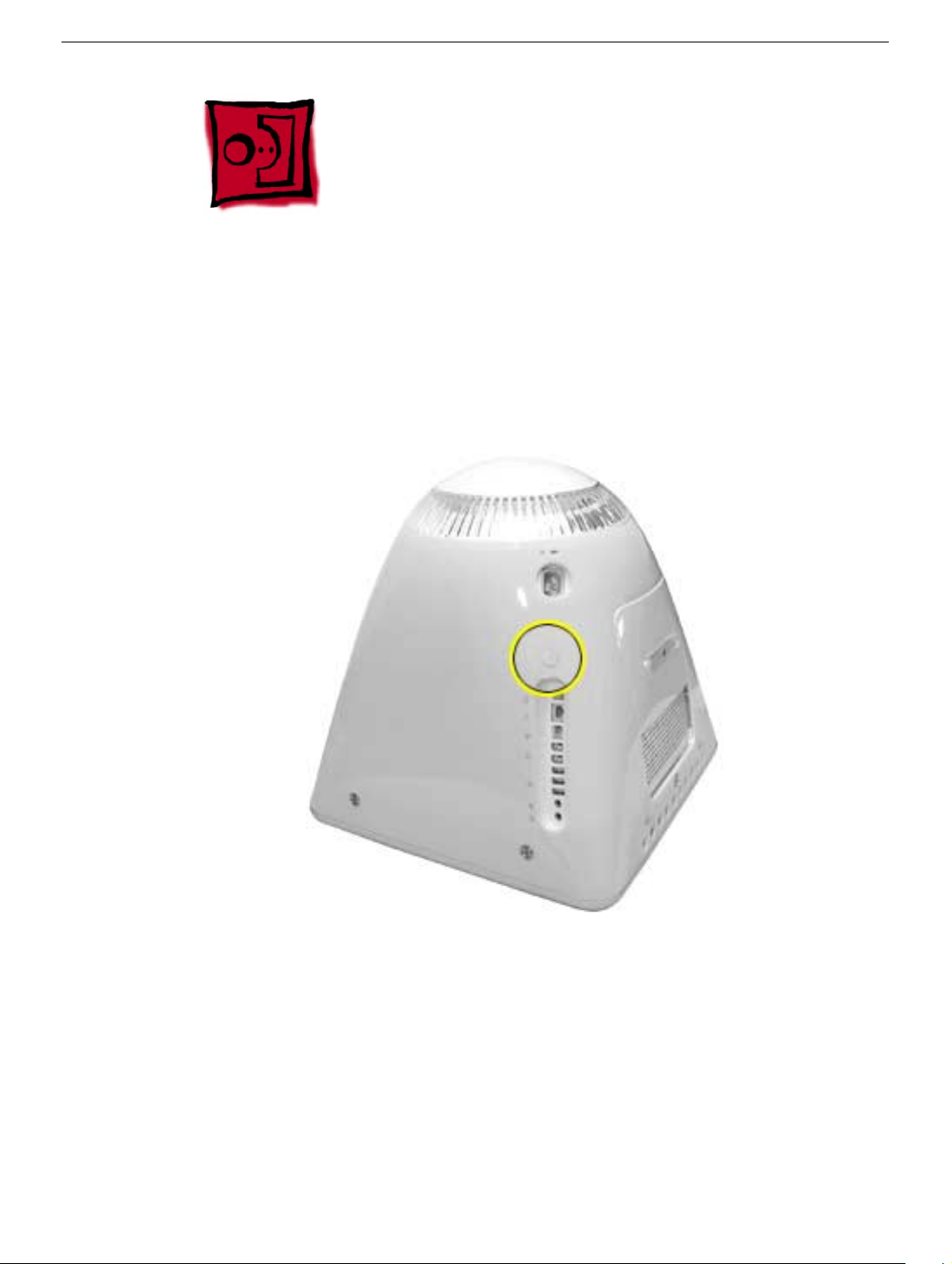
1. Remove the screw on the user access door (shown below).
2. Gently remove the access door.
User Access Door
eMac (ATI Graphics) Take Apart -
7
Feet
Tools
This procedure requires the following tools:
• Phillips #2 screwdriver
Part Location
Preliminary Steps
Before you begin, do the following:
• Place the computer face down on an ESD mat.
8
eMac (ATI Graphics) Take Apart
Feet
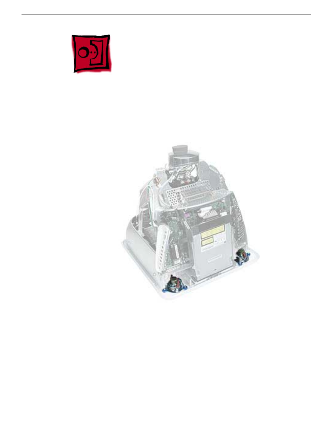
Procedure
1. Remove the two foot screws. Set the plastic feet aside.
Feet
eMac (ATI Graphics) Take Apart -
9
Power Button
Tools
• Needlenose pliers
Note:
Follow the Replacement Note procedure (step 2) only if you are replacing a
defective power button.
Part Location
Preliminary Steps
Before you begin, do the following:
• Place the computer face down on an ESD mat.
• Remove the user access panel.
• Remove the feet.
• Remove the rear housing.
10
eMac (ATI Graphics) Take Apart
Power Button
Procedure
1. Disconnect the power button cable from the power button located inside the rear
housing.
2. Lift the rear housing off the bezel.
page, “Power Button Cable Check” before replacing the rear housing.
Replacement Note:
Refer to the topic on the next
Power Button
eMac (ATI Graphics) Take Apart -
11
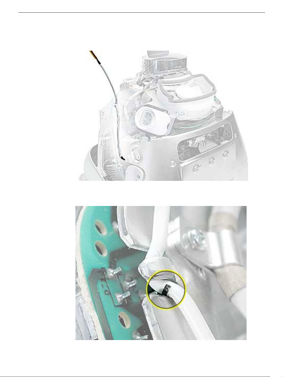
Power Button Cable Check
1. Check that the power button cable in drawn tight before you attach the other end of the
cable to the power button (located inside the rear housing).
2. Also, check that the cable is tucked under the chassis tab (as shown) and that the
black mark on the cable lines up with the chassis (circled below).
12
eMac (ATI Graphics) Take Apart
Power Button
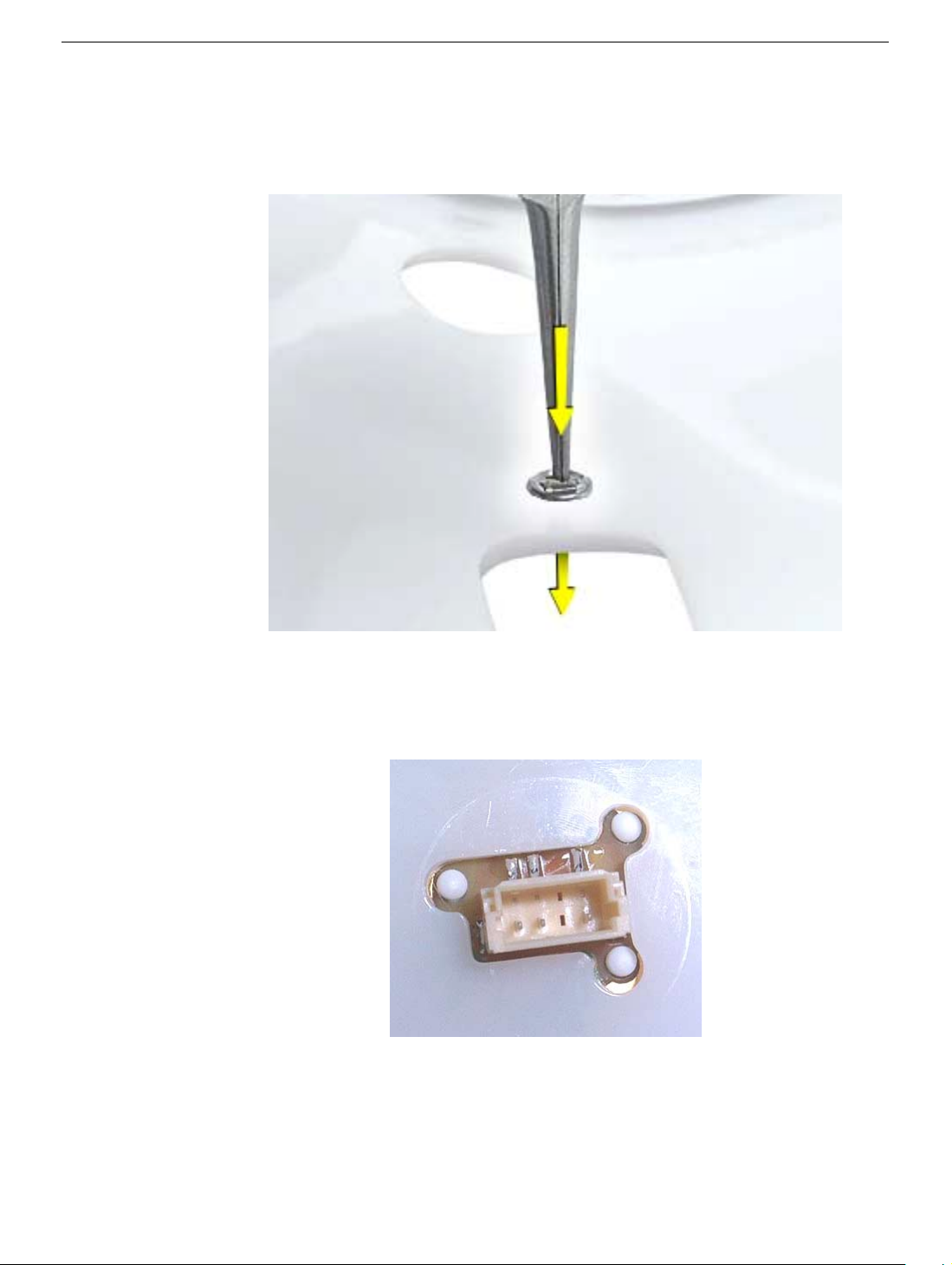
Power Button Replacement
1. Continue with this procedure only if you are replacing a defective power button. With a
needlenose pliers, push the power button through the retaining ring. The power button
will pop off rear housing and the retaining ring may get stuck on the pliers.
2. Obtain the new power button and peel the sticky backing off the power button. Position
the power button into the hole on the rear housing (as shown below).
picture below is looking at the power button from the inside of the rear housing.
3. Place the retaining ring over the power button connector and press down firmly.
Note:
The
Power Button
eMac (ATI Graphics) Take Apart -
13
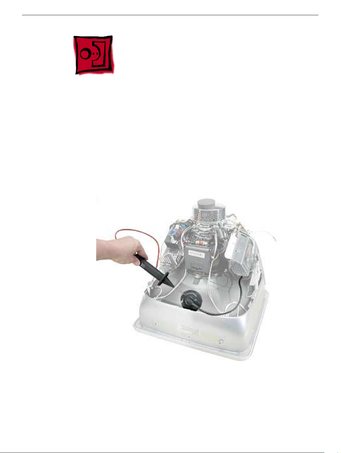
CRT Discharge
Warning:
injury, always review the Service Foundations: CRT Displays course for safety information.
It can be found at: http://service.info.apple.com/service_training/training.html. Click on
Desktop Certification Courses and select the Service Foundations: CRT Displays link.
Warning:
an ongoing ground connection.
This product contains high voltage and a high-vacuum picture tube. To prevent
Never use a grounding wriststrap until after discharging the CRT and setting up
Safety Guidelines:
Whenever the rear housing of the computer is removed and before replacing a module,
you must
1. Discharge the CRT (shown below) and remove the anode cap.
2. Establish an ongoing ground by using a cable with alligator clips at both ends.
Connect one end to the anode aperture, and connect the other end to the metal CRT
frame (as shown below).
3. With the CRT discharged and the ongoing ground in place wear a grounding
wriststrap to prevent equipment damage from static electricity.
14
eMac (ATI Graphics) Take Apart
CRT Discharge
Speakers
Tools
This procedure requires the following tools:
• Phillips #2 screwdriver
Part Location
Speakers
Preliminary Steps
Before you begin, do the following:
• Place the computer face down on an ESD mat.
• Remove the user access door.
• Remove the feet.
• Remove the rear housing.
• Discharge the CRT.
eMac (ATI Graphics) Take Apart -
15
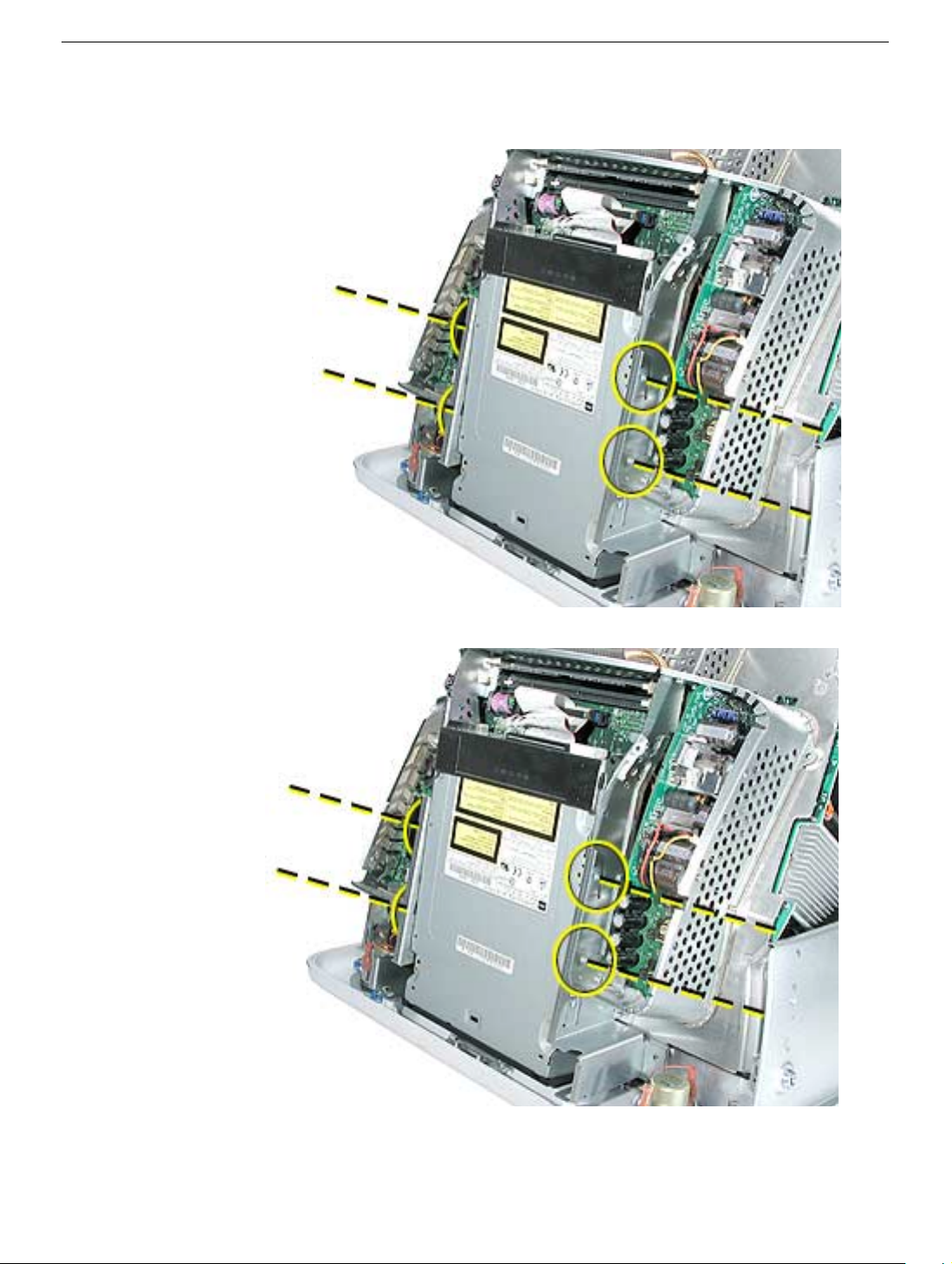
Procedure
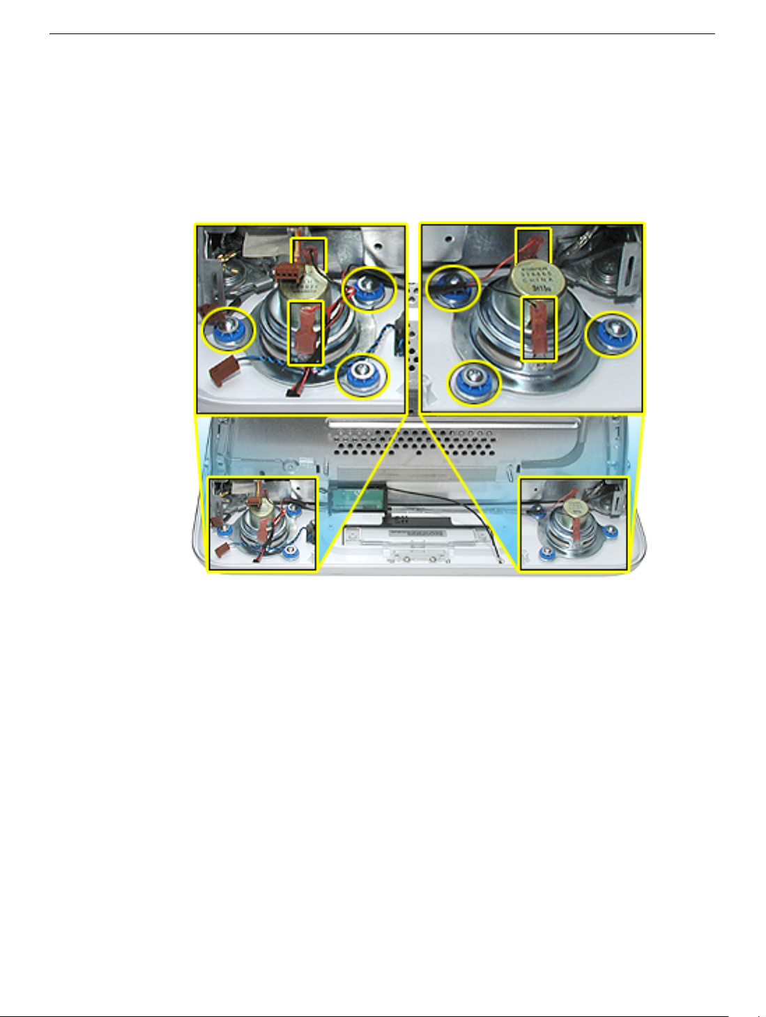
1. Remove the left and right speaker screws (circled in the top photos). There are three
screws per speaker.
2. Disconnect the two spade connectors (see rectangles in the top photos) on each
speaker.
3. Lift the speakers out of the front bezel.
16
eMac (ATI Graphics) Take Apart
Speakers
Fan
Tools
This procedure requires the following tools:
• Phillips #2
Part Location
Fan
Preliminary Steps
Before you begin, do the following:
• Place the computer face down on an ESD mat.
• Remove the user access door.
• Remove the feet.
• Remove the rear housing.
• Discharge the CRT.
eMac (ATI Graphics) Take Apart -
17
Procedure
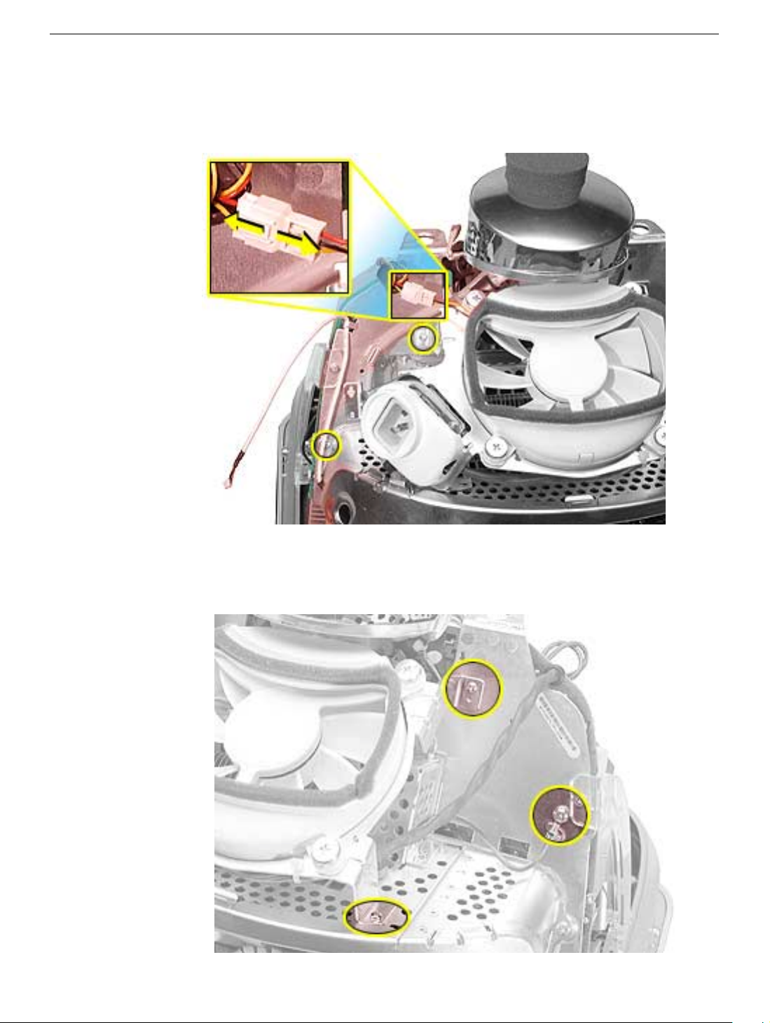
1. On the left side of the fan, disconnect the fan cable and remove the two screws
(circled).
2. On the right side of the fan, remove three screws (the green cable goes to the ground
screw).
and the screw on the bottom left is a fine thread screw.
Replacement Note:
The screw circled on the top left is a self-tapping screw,
18
eMac (ATI Graphics) Take Apart
Fan
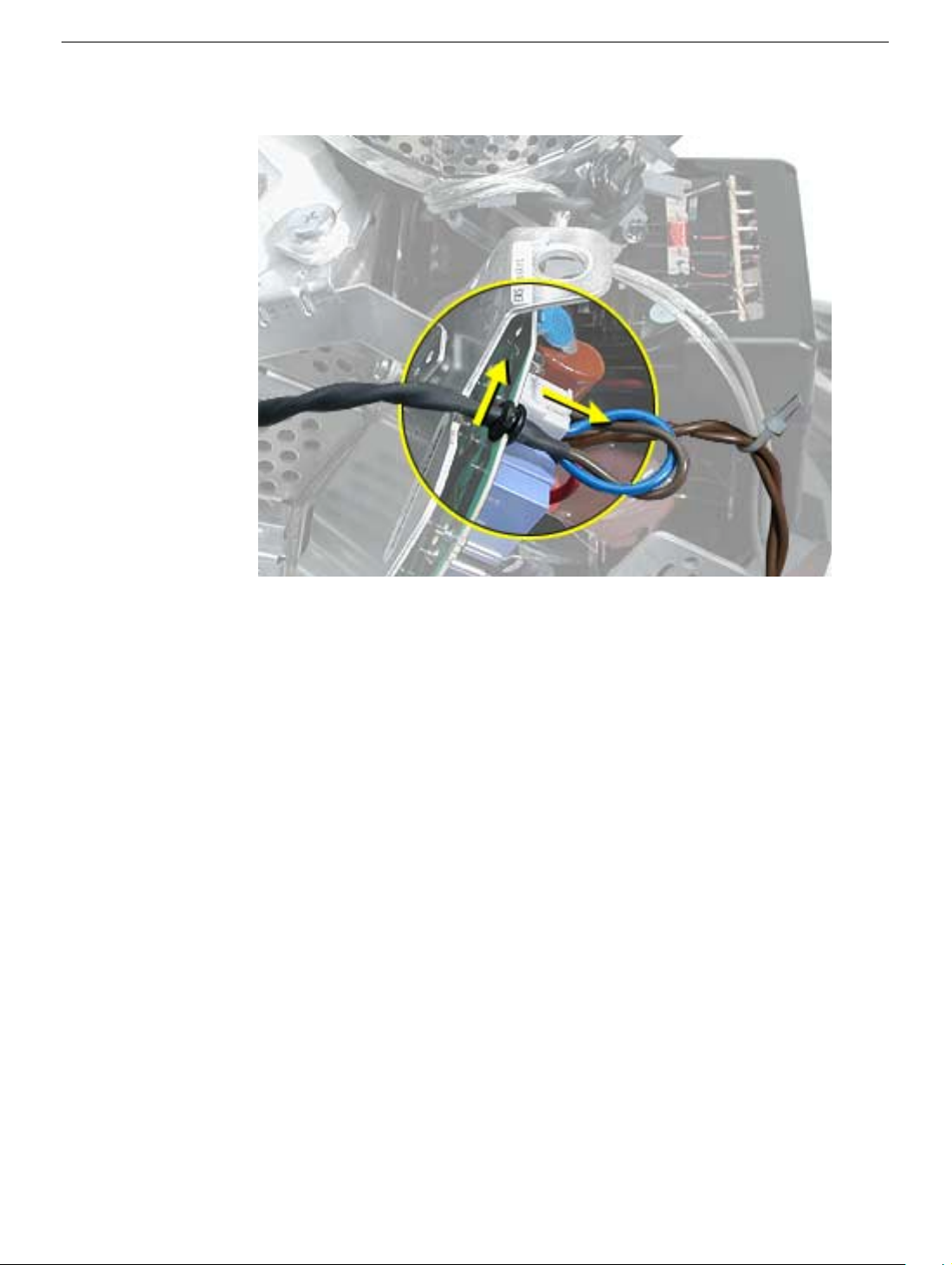
3. Wiggle the fan cable up and out of the groove in the chassis and then disconnect the
fan connector from the board.
4. To remove the fan, turn the computer so the fan is facing you. Grab onto the fan near
the AC plug and the bottom right corner of the fan. Gently pull the fan toward you and
away from the chassis. Be very careful of the CRT neck.
Fan
eMac (ATI Graphics) Take Apart -
19
Faraday Plate
Tools
This procedure requires the following tools:
• Phillips #2
Part Location
Preliminary Steps
• Place the computer face down on an ESD mat.
• Remove the user access door.
• Remove the feet.
• Remove the rear housing.
• Discharge the CRT.
20
eMac (ATI Graphics) Take Apart
Faraday Plate
Procedure
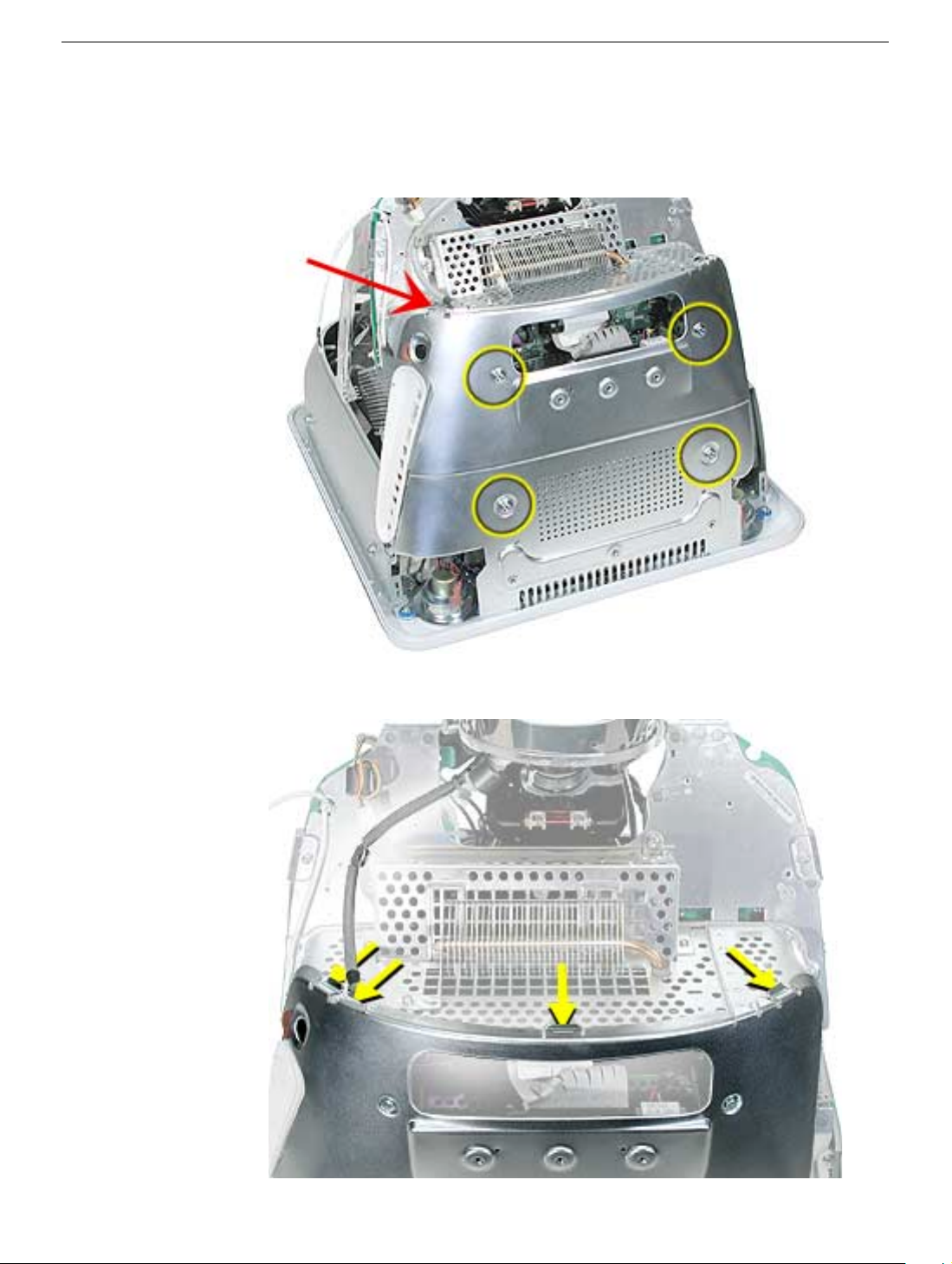
1. Remove the four screws on the Faraday plate.
of the gray cable (see red arrow) on the top left side of the Faraday plate. Be careful
the cable doesn’t get pinched when the Faraday plate is replaced.
Replacement Note:
Note the position
2. Gently pry the top half of the Faraday plate away from the chassis in the direction of
the arrows.
Note:
The gray cable (on left) rests in a groove under the Faraday plate.
Faraday Plate
eMac (ATI Graphics) Take Apart -
21
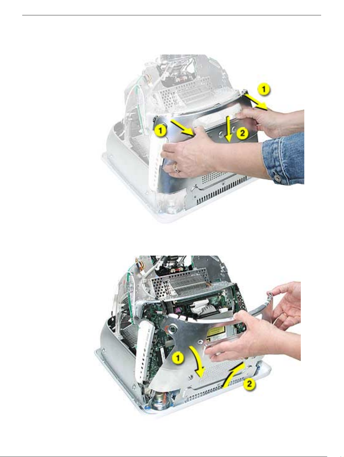
3. Pull the Faraday plate back (#1) and then push it down (#2) to unhook the metal tabs
on the Faraday plate from the cutouts (see graphic on the next page) in the chassis.
4. Continue to pull the Faraday plate back (#1) to unhook the tabs from the chassis. Pull
the Faraday plate up (#2) to remove it from the chassis.
22
eMac (ATI Graphics) Take Apart
Faraday Plate
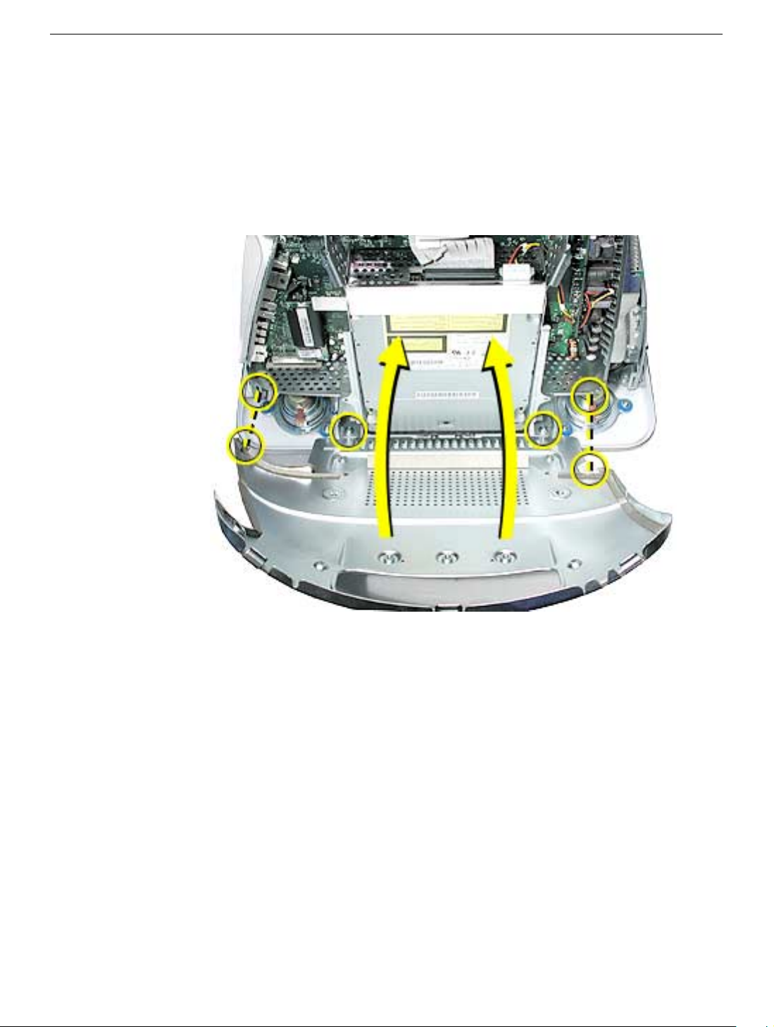
Faraday Replacement
1. Looking from the top down, line up the metal tabs with the cutouts in the chassis
(circled on the right and left) and the slots on the Faraday plate with the white plastic
guides on the bezel (circled on the right and left sides of the optical drive).
2. Raise the Faraday plate up and attach it to the frame on the digital assembly. Be
careful that the gray cable (shown in step 2 on the previous page) does not get
pinched in the Faraday plate.
Faraday Plate
eMac (ATI Graphics) Take Apart -
23
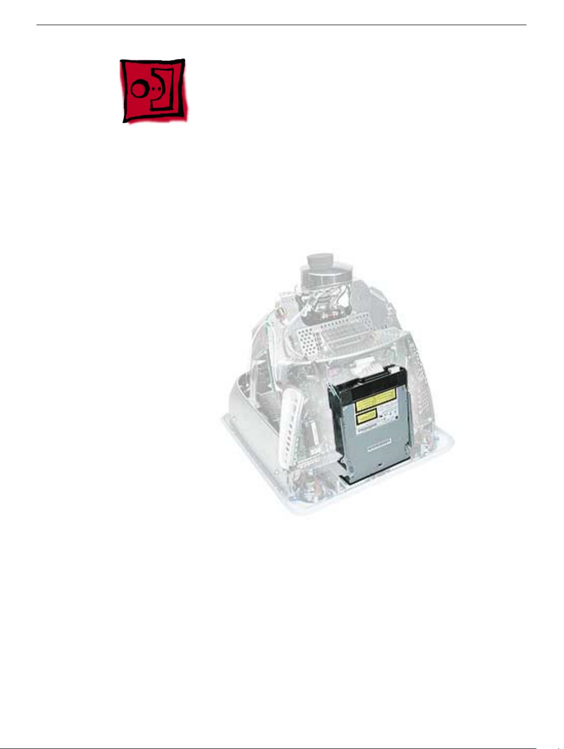
Optical Drive
Tools
This procedure requires the following tools:
• Phillips #2 screwdriver
Part Location
Preliminary Steps
Before you begin, do the following:
• Place the computer face down on an ESD mat.
• Remove the user access door.
• Remove the feet.
• Remove the rear housing.
• Discharge the CRT.
• Remove the Faraday plate.
24
eMac (ATI Graphics) Take Apart
Optical Drive
Procedure
1. Disconnect the data cable and the power cable at the top of the optical drive.
2. Remove the four screws connecting the optical drive to the chassis.
3. Holding the optical drive by the top or bottom end, tilt the optical drive out of the
chassis.
Place the EMI shield on the replacement drive.
Replacement Note:
Remove the EMI shield on the end of the optical drive.
Optical Drive
eMac (ATI Graphics) Take Apart -
25
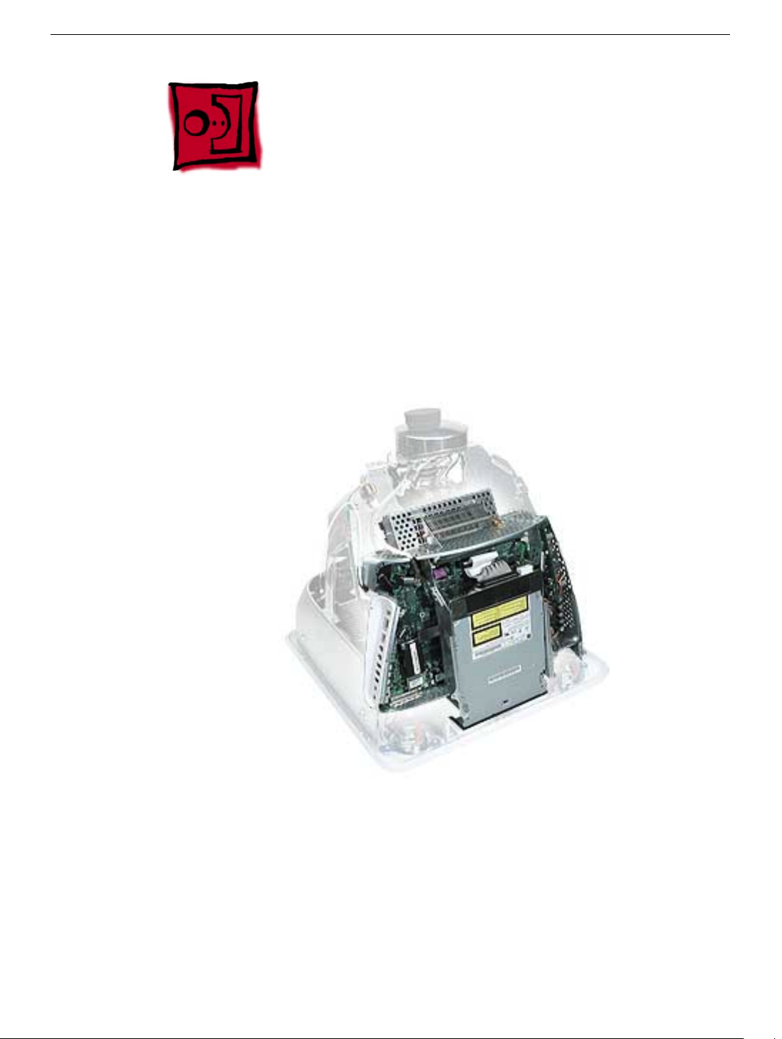
Digital Assembly
Tools
This procedure requires the following tools:
• Phillips #2
Part Location
Preliminary Steps
Before you begin, do the following:
• Place the computer face down on an ESD mat
• Remove the user access door
• Remove the feet
• Remove the rear housing
• Discharge the CRT
26
eMac (ATI Graphics) Take Apart
Digital Assembly

• Remove the fan
• Remove the Faraday plate
• Remove the AirPort Extreme Card (if present)
Digital Assembly
eMac (ATI Graphics) Take Apart - 27
Loading...