


 Loading...
Tropos Networks
Outdoor Installation Guide
Tropos Networks, Inc.
1710 South Amphlett Boulevard
Suite 304
San Mateo, CA 94402
USA
Copyright © 2003 |
Part No. 100226 Rev A |
Tropos Networks, Inc. |
|
All rights reserved. |
Published August 2003 |

Copyright Notice
©2003 Tropos Networks, Inc. All rights reserved. Tropos Networks is a registered trademark of Tropos Networks, Inc. in the United States and certain other jurisdictions. Specifications are subject to change without notice.
Loctite is a registered trademark of Loctite Corporation, USA.
FCC Notice to Users and Operators
This equipment has been tested and found to comply with the limits for a Class A digital device, pursuant to Part 15 of the FCC Rules. These limits are designed to provide reasonable protection against harmful interference when the equipment is operated in a commercial environment. This equipment generates, uses, and can radiate radio frequency energy and, if not installed and used in accordance with the instruction manual, may cause harmful interference to radio communications. Operation of this equipment in a residential area is likely to cause harmful interference, in which case the user will be required to correct the interference at his own expense. If this equipment does cause interference to radio or television reception, which can be determined by turning the equipment off and on, the user is encouraged to correct the interference by using one of the following measures:
Reorient or relocate the receiving antenna.
Increase separation between the equipment and receiver.
Connect the equipment to an outlet on a circuit different from that to which the receiver is connected.
Consult the dealer or an experienced radio/TV technician.
This Part 15 radio device operates on a non-interference basis with other devices operating at this frequency. Any changes or modification to said product not expressly approved by Tropos Networks could void the user's authority to operate this device.
Warning
You can be killed installing this device!
You can be killed if the 5110 antennas come near electric power lines.
Carefully read and follow all instructions in this manual.
By nature of the installation, you may be exposed to hazardous environments, and high voltage. Use caution when installing the outdoor system.
ii |
Outdoor Unit Hardware Installation Guide |

Contents
1 Installing the Tropos 5110 Wi-Fi Cell . . . . . . . . . . . . . . . . . . . . . . . . . . . . . 1
Preparing for Installation . . . . . . . . . . . . . . . . . . . . . . . . . . . . . . . . . . . . . . . . 1 Model Numbers . . . . . . . . . . . . . . . . . . . . . . . . . . . . . . . . . . . . . . . . . . . . . . 1 Installation Hardware and Tools . . . . . . . . . . . . . . . . . . . . . . . . . . . . . . . . . 3 Site Planning . . . . . . . . . . . . . . . . . . . . . . . . . . . . . . . . . . . . . . . . . . . . . . . . 3 Location Guidelines. . . . . . . . . . . . . . . . . . . . . . . . . . . . . . . . . . . . . . . . . . . 3 Antenna Options . . . . . . . . . . . . . . . . . . . . . . . . . . . . . . . . . . . . . . . . . . . . . 4 Site Surveys . . . . . . . . . . . . . . . . . . . . . . . . . . . . . . . . . . . . . . . . . . . . . . . . 4 Power Source . . . . . . . . . . . . . . . . . . . . . . . . . . . . . . . . . . . . . . . . . . . . . . . 4 Safety . . . . . . . . . . . . . . . . . . . . . . . . . . . . . . . . . . . . . . . . . . . . . . . . . . . . . 5
Mounting Instructions . . . . . . . . . . . . . . . . . . . . . . . . . . . . . . . . . . . . . . . . . . . 5 Metal Pole Mounting . . . . . . . . . . . . . . . . . . . . . . . . . . . . . . . . . . . . . . . . . . 6 Wood Pole Mounting . . . . . . . . . . . . . . . . . . . . . . . . . . . . . . . . . . . . . . . . . . 8 Tower Mounting. . . . . . . . . . . . . . . . . . . . . . . . . . . . . . . . . . . . . . . . . . . . . . 9 Streetlight Mounting . . . . . . . . . . . . . . . . . . . . . . . . . . . . . . . . . . . . . . . . . 10 Mounting for Downward Facing Antennas . . . . . . . . . . . . . . . . . . . . . . . . 12
Connecting Antennas . . . . . . . . . . . . . . . . . . . . . . . . . . . . . . . . . . . . . . . . . . 13 Waterproofing Antenna Connections . . . . . . . . . . . . . . . . . . . . . . . . . . . . 15 Replacing the Antenna . . . . . . . . . . . . . . . . . . . . . . . . . . . . . . . . . . . . . . . 16 Grounding the Tropos 5110 Wi-Fi Cell. . . . . . . . . . . . . . . . . . . . . . . . . . . . . 17 Grounding the Data Protection Device . . . . . . . . . . . . . . . . . . . . . . . . . . . 18 Connecting Power . . . . . . . . . . . . . . . . . . . . . . . . . . . . . . . . . . . . . . . . . . . . 18 Categories of Power . . . . . . . . . . . . . . . . . . . . . . . . . . . . . . . . . . . . . . . . . 19 Connecting DC Power (Power over Ethernet). . . . . . . . . . . . . . . . . . . . . . 21 Connecting to AC Power (Category C) . . . . . . . . . . . . . . . . . . . . . . . . . . . 24 Connecting to Streetlight Power (Category C) . . . . . . . . . . . . . . . . . . . . . 25 Connecting a Data Port . . . . . . . . . . . . . . . . . . . . . . . . . . . . . . . . . . . . . . . . 26 Connecting Peripherals . . . . . . . . . . . . . . . . . . . . . . . . . . . . . . . . . . . . . . . . 29
A Safety Information . . . . . . . . . . . . . . . . . . . . . . . . . . . . . . . . . . . . . . . . . . . 30
Safety Information for the Tropos 5110 Wi-Fi Cells . . . . . . . . . . . . . . . . . . . 30 Service Instructions . . . . . . . . . . . . . . . . . . . . . . . . . . . . . . . . . . . . . . . . . . . 31
Outdoor Hardware Installation Guide |
iii |

B Product Specifications . . . . . . . . . . . . . . . . . . . . . . . . . . . . . . . . . . . . . . . 36
C AC Wiring Diagrams . . . . . . . . . . . . . . . . . . . . . . . . . . . . . . . . . . . . . . . . . 40
Index . . . . . . . . . . . . . . . . . . . . . . . . . . . . . . . . . . . . . . . . . . . . . . . . . . . . . . 43
Outdoor Hardware Installation Guide |
iv |

Installing the Tropos 5110 Wi-Fi Cell
This guide explains how to install the Tropos 5110 a Wi-Fi cell safely and is intended for a trained technical professionals. It covers the following topics:
Preparing for Installation
Mounting Instructions
Connecting Antennas
Grounding the Tropos 5110 Wi-Fi Cell
Connecting Power
Connecting a Data Port
Connecting Peripherals
Preparing for Installation
The Tropos 5110 Wi-Fi Cell must be installed by a trained professional, value added reseller, or systems integrator who is familiar with RF cell planning issues and regulatory limits defined by the FCC for RF exposure (sections 1.1307). This section lists the required equipment and model numbers and explains how to identify and prepare the installation site.
Model Numbers
Table 1 lists the model numbers and ranges for the units discussed in this guide. Figure 1 on page 2 shows an exploded view of the Tropos 5110 Wi-Fi Cell.
Table 1 Tropos 5110 Wi-Fi Cell Model Numbers
Model |
|
Model Number |
|
|
|
Tropos 5110 |
Wi-Fi Cell; -30 deg to 55 deg C; N connectors |
51102100 |
(requires external antenna) |
|
|
Tropos 5110 |
Wi-Fi Cell; -30 deg to 55 deg C; 7.4 dBi; Antennas, |
51103000 |
bracketry |
|
|
|
|
|
Outdoor Hardware Installation Guide |
1 |

Preparing for Installation
Note
The antenna(s) used for this transmitter must be omni directional antennas with a gain of 7.4dBi or less. Antenna(s) must be installed by a trained professional. Operating the unit with non-qualified antennas is a violation of FCC Rules Part 15.203(c), Code of Federal Regulations, Title 47.
Rx diversity antenna
Pole bracket
Slide bracket
Bubble |
Hose |
level |
clamps |
Tx/Rx antenna
#10-32 hex head 5/16"
machine screws  Sun shield x5
|
AC input |
|
|
|
power |
|
|
|
connector |
|
|
10/100 BaseT |
Extruded |
|
|
management port |
|
|
|
(PoE input power) |
housing |
|
|
|
|
|
Fuse |
|
Red/green |
Fuse |
cover guard |
|
holders |
|
|
|
status |
|
|
|
|
|
|
10/100 BaseT |
indicator |
|
Split bolt |
|
|
ground lug |
|
LAN port |
|
|
|
|
|
|
|
(PoE input power) |
|
|
fhp_055 |
Figure 1 Tropos 5110 Wi-Fi Cell exploded view
Outdoor Hardware Installation Guide |
2 |

Preparing for Installation
Installation Hardware and Tools
Tropos Networks provides the following accessories to install the Tropos 5110 Wi-Fi Cell:
One mounting bracket
Two 4-inch diameter hose clamps
Four 6-inch diameter hose clamps
Five 5/16-inch #10-32 stainless steel hex head machine screws
You must supply the following tools:
5/16 inch nut driver
1/4-inch flat blade screwdriver
Tower mounting only: supply stainless or galvanized steel channel stock and 1/2-inch or 5/8-inch nuts, bolts, and washers to connect to the tower arm.
Wood pole mounting only: two 5/8-inch diameter, 3-inch long lag bolts
Site Planning
To ensure safe and durable wiring, installation of the Tropos 5110 Wi-Fi Cell must follow appropriate electrical and building codes. Follow the National Electrical Code (NEC) requirements, unless local codes in your area take precedence over the NEC code.
The following distance limits apply to installations that have 10/100 Base-T Category 5 network cables attached to the Tropos 5110 Wi-Fi Cell:
100 meters between devices for 100BaseT operation
366 meters for 10BaseT operation.
The Ethernet duplex and speed setting is configurable.
Location Guidelines
The Tropos 5110 Wi-Fi Cell is a radio device and therefore susceptible to interference that can reduce throughput and range. Follow these guidelines to ensure the best performance:
Install the unit in an area where trees, buildings, and large steel structures do not obstruct radio signals to and from the antenna. Direct line-of-sight operation is best.
Install the unit away from microwave ovens or other devices operating in the 2.4 GHz frequency range.
Install the units away from other possible sources of 2.4 GHz WLAN interference, such as cordless phones, home spy cameras, frequency hopping (FHSS) and DSSS LAN transceivers (non-802.11b), electronic news gathering video links, radars, amateur radios, land mobile radio services, local government sites (such as law enforcement), fixed microwave services, local TV transmission and private fixed point transmitters.
Outdoor Hardware Installation Guide |
3 |

Preparing for Installation
Antenna Options
You can purchase the Tropos 5110 Wi-Fi Cell with an integrated omni-directional antenna (Model 51103000) or use your own external antenna (Model 51102100). Omni-directional antennas are best for systems requiring a signal distribution in more than one direction. To comply with FCC RF exposure limits, locate antennas at a minimum distance of 7.9 inches (20cm) from people.
Note
The antenna(s) used for this transmitter must be omni directional antennas with a gain of 7.4dBi or less. Antenna(s) must be installed by a trained professional. Operating the unit with non-qualified antennas is a violation of FCC Rules Part 15.203(c), Code of Federal Regulations, Title 47.
Site Surveys
Due to; variations in component configuration, placement, and physical environment, each installation is unique. Before installing the Tropos 5110 Wi-Fi Cell, perform a site survey to determine the optimum placement of units for maximum range, coverage, and network performance. Consider the following factors when performing a site survey:
Data rates—Sensitivity and range are inversely proportional to data bit rates. The maximum radio range is achieved at the lowest workable data rate. A decrease in receiver threshold sensitivity occurs as radio data increases.
Antenna type and placement—Proper antenna configuration is a critical factor in maximizing radio range. As a general rule, range increases in proportion to antenna height and gain.
Physical environment—Clear or open areas provide better radio range than closed or filled areas. The less cluttered the operating environment, the greater the range.
Obstructions—A physical obstruction, such as a building or tree, can block or hinder communication. Avoid locating antennas in a location where there is an obstruction between sending and receiving antennas.
Building materials—Radio penetration is influenced by the building material used in construction. For example, drywall construction permits greater range than concrete blocks. Metal or steel construction is a barrier to radio signals.
Diversity—The Tropos 5110 Wi-Fi Cell supports RX diversity, which requires two antennas.
Power Source
The Tropos 5110 Wi-Fi Cell supports 4 options for connecting to a power source:
DC power source (power over Ethernet) — input voltage 24 to 48 VDC
AC power source (3-wire service) — 120/208 VAC
Outdoor Hardware Installation Guide |
4 |

Mounting Instructions
NEMA plug, for streetlight photoelectric control power tap (2-wire service) — 120/208 VAC
Warning
Connect the AC powered outdoor system only to 120/208V AC power sources. Do not connect it to a power source of higher voltage.
Safety
Installing the Tropos 5110 Wi-Fi Cell can pose a serious hazard. Be sure to take precautions to avoid the following:
Exposure to high voltage lines during installation
Falls when working at heights or with ladders
Injuries from dropping tools
Contact with AC wiring
Mounting Instructions
This section explains how to mount the Tropos 5110 Wi-Fi Cell on a pole, tower, or streetlight.
Note
The sun shield for the Tropos 5110 Wi-Fi Cell is designed to accommodate antennas facing upward. If conditions at the installation site require that the antennas face downward, you must remove the sun shield and reattach it upside down. See “Mounting for Downward Facing Antennas” on page 12.
Outdoor Hardware Installation Guide |
5 |
Mounting Instructions
Metal Pole Mounting
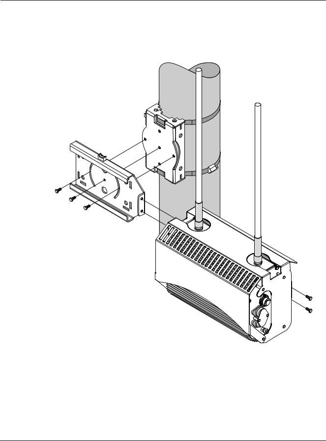
Figure 2 shows a typical installation with the Tropos 5110 Wi-Fi Cell mounted on an outdoor metal pole.
Pole bracket (rotated)
Sliding bracket
Tropos 5110 Wi-Fi Cell with sun shield
fhp 037
Figure 2 Metal Pole Mounting
To mount the Tropos 5110 Wi-Fi Cell on a metal pole:
1.Select a mounting location. You can attach the Tropos 5110 Wi-Fi Cell to any pipe or pole with diameter 1.75” to 10”.
2.If the pole is vertical, use a 5/16-inch nut driver to remove the 3 bolts that attach the pole bracket to the sliding bracket. Rotate the pole bracket 90 degrees and reattach it to the
Outdoor Hardware Installation Guide |
6 |
Mounting Instructions
sliding bracket. Tighten the center bolt, but keep the bolts in the curved grooves slightly loose to permit rotation.
3.Slip the flat portion of the hose clamps under the inside lips of the pole bracket.
4.Use the hose clamps to attach the pole bracket to the pole. Depending upon the diameter of the pole, you may need to use a single small clamp, single large clamp, or pair of large clamps joined together.
5.Level the pole bracket by adjusting the hose clamp and rotating the bracket along the curved grooves. Use the internal bubble levels for reference.
6.Tighten all the mounting bolts.
7.Slide the Tropos 5110 Wi-Fi Cell into place and secure it at the end with two #10-32 hex head machine screws.
To continue installing the outdoor system, see “Connecting Antennas” on page 13.
Outdoor Hardware Installation Guide |
7 |
Mounting Instructions
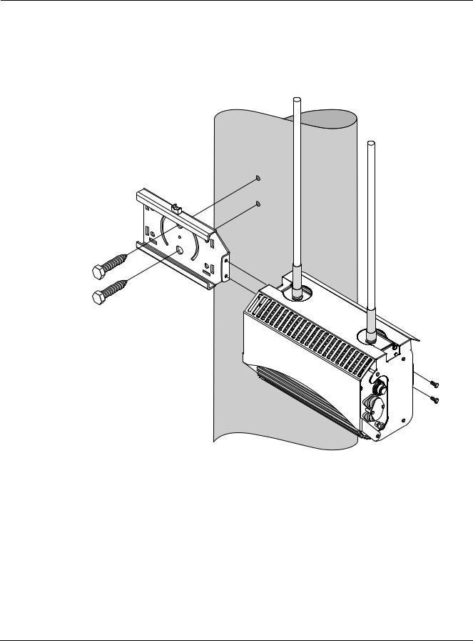
Wood Pole Mounting
Figure 3 shows a typical installation with the Tropos 5110 Wi-Fi Cell mounted on an outdoor wood pole.
fhp_037w
Figure 3 Wood Pole Mounting
To mount the Tropos 5110 Wi-Fi Cell on a wood pole:
1.Select a mounting location. You can attach the Tropos 5110 Wi-Fi Cell to any outdoor wood pole of diameter at least 1.75 inches.
2.Remove the pole bracket from the sliding bracket.
3.Level the sliding bracket against the pole.
4.Use two 5/8-inch lag bolts to attach the sliding bracket to the pole.
Outdoor Hardware Installation Guide |
8 |
Mounting Instructions
5.Slide the Tropos 5110 Wi-Fi Cell into place and secure it at the end with two #10-32 hex head machine screws.
To continue installing the outdoor system, see “Connecting Antennas” on page 13.
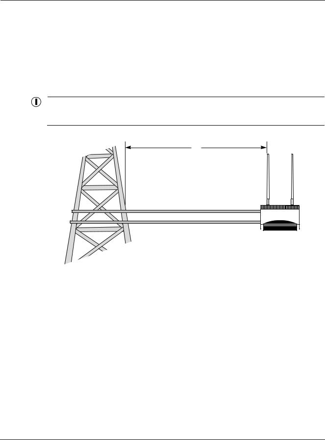
Tower Mounting
You can mount the outdoor system to an outdoor tower.
Note
At the antenna level, the Tropos 5110 Wi-Fi Cell must be free from metal obstruction within a 4-foot radius (Figure 4 on page 9).
4'
Channel stock
Brackets not included
Figure 4 Tower Mounting
To mount the Tropos 5110 Wi-Fi Cell on a tower:
1.Remove the pole bracket from the sliding bracket.
2.Make a tower bracket by attaching the sliding bracket directly to any stainless steel or galvanized steel channel stock.
3.Attach the bracket assembly to the tower arm so that the slides are horizontal.
4.Level the bracket assembly by rotating the sliding bracket along the curved grooves.
5.Tighten the mounting bolts.
6.Slide the Tropos 5110 Wi-Fi Cell into place and secure it at the end with two #10-32 hex head machine screws.
To continue installing the outdoor system, see “Connecting Antennas” on page 13.
Outdoor Hardware Installation Guide |
9 |
Mounting Instructions
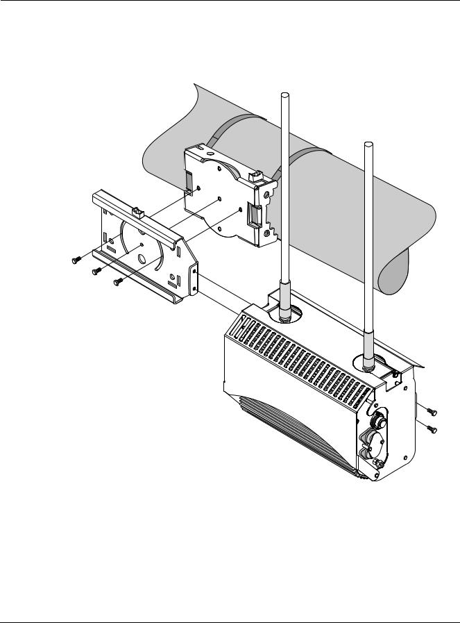
Streetlight Mounting
You can mount the Tropos 5110 Wi-Fi Cell on the horizontal or angled arm of a streetlight. Figure 2shows a typical streetlight mounting installation.
fhp_039
Figure 5 Streetlight Mounting
To mount the Tropos 5110 Wi-Fi Cell on a streetlight:
1.Select a mounting location. You can attach the Tropos 5110 Wi-Fi Cell to any streetlight arm with diameter 1.75” to 10”.
2.If the angle of the streetlight arm has a vertical orientation, use a 5/16-inch nut driver to remove the 3 bolts that attach the pole bracket to the sliding bracket. Rotate the pole bracket
Outdoor Hardware Installation Guide |
10 |
Loading...