


D2071A
Operation & Installation Guide
EN Fire Alarm Control Panel

D2071A | Operations & Installation Guide | Contents
|
Contents |
|
1.0 |
Overview .......................................................................... |
4 |
1.1 |
Communicator ......................................................... |
4 |
1.2 |
RFI and Lightning Protection ............................... |
4 |
1.3 |
Materials Included .................................................. |
4 |
1.3.1 |
D2071A ..................................................................... |
4 |
1.3.2 |
D2071AC .................................................................. |
4 |
1.4 |
Required Materials ................................................. |
4 |
1.5 |
Listings and Approvals ........................................... |
4 |
1.5.1 |
Mandatory Connections ........................................ |
5 |
1.6 |
Slave Communicator Applications ..................... |
6 |
1.6.1 |
Slave Application Power ....................................... |
6 |
1.6.2 |
UL Listed Enclosure ............................................... |
6 |
1.7 |
Receiving Equipment ............................................. |
6 |
1.8 |
D2071A Control Panel Assembly ....................... |
6 |
1.8.1 |
Terminal Strip ........................................................... |
6 |
1.8.2 |
Programmer Connector (J3) ................................. |
6 |
1.8.3 |
D2071A Enclosure Cover .................................... |
6 |
1.8.4 |
Phone Line Trouble Buzzer ................................... |
6 |
1.8.5 |
Phone Line Trouble LED ....................................... |
7 |
1.8.6 |
Mounting Tabs ......................................................... |
7 |
1.8.7 |
Alternate Modular Telephone Jack ..................... |
7 |
1.8.8 |
Primary Modular Telephone Jack ........................ |
7 |
1.8.9 |
Phone Line Trouble Relay (K5) ........................... |
7 |
1.8.10 |
Initiating Circuit Alarm Relay (K6) ...................... |
7 |
1.8.11 |
Strain Relief Tab ..................................................... |
7 |
2.0 |
Installation ...................................................................... |
8 |
2.1 |
Earth Ground Wiring ............................................ |
10 |
2.1.1 |
12 VAC Mode ........................................................ |
10 |
2.1.2 |
24 VDC Mode ....................................................... |
10 |
2.2 |
Zone 1, Alarm Initiating Circuit ......................... |
10 |
2.2.1 |
Class “A” Circuit Parameters ............................. |
10 |
2.2.2 |
Retard and Reset Times ..................................... |
10 |
2.2.3 |
Wiring ....................................................................... |
11 |
2.3 |
Zones 2 and 3 (Supervisory Circuits) ............. |
11 |
2.3.2 |
Mode 2 .................................................................... |
11 |
2.3.3 |
Mode 3 .................................................................... |
12 |
2.3.4 |
Mode 1 and Mode 2 Restrictions .................... |
12 |
2.3.5 |
Wiring ....................................................................... |
12 |
2.3.6 |
Class “B” Circuit Parameters ............................ |
12 |
2.4 |
Initiating Circuit Alarm Relay ............................. |
12 |
2.4.1 |
Installation ............................................................... |
12 |
2.4.2 |
Wiring ....................................................................... |
13 |
2.5 |
Phone Line Trouble Relay ................................... |
13 |
2.5.1 |
Installation ............................................................... |
13 |
2.5.2 |
Wiring ....................................................................... |
13 |
2.6 |
Primary Power Supply .......................................... |
13 |
2.6.1 |
12 VAC Mode ........................................................ |
13 |
2.6.2 |
24 VDC Mode ....................................................... |
14 |
2.7Secondary Power Supply and
|
Charging Circuit (12 VAC Mode Only) ........... |
14 |
2.7.1 |
Battery ..................................................................... |
14 |
2.7.2 |
12 VAC Battery Discharge and |
|
|
Recharge Schedule ............................................. |
15 |
2.8 |
Telephone Connections ....................................... |
15 |
2.8.1 |
Telephone Cord Installation ................................ |
15 |
2.8.2 |
Location ................................................................... |
15 |
2.8.3 |
Telephone Line Supervision ............................... |
15 |
2.8.4 |
Call Routing ........................................................... |
16 |
2.8.5 |
Notification ............................................................. |
16 |
2.9 |
Cable Tie Installation ........................................... |
16 |
2.9.1 |
Screw Mounting .................................................... |
17 |
2.9.2 |
D2002 Mounting Plate ....................................... |
17 |
2.9.3 |
Adhesive Strip Mounting ..................................... |
17 |
2.10 |
End User Instruction Label ................................. |
17 |
3.0 |
Programming .............................................................. |
18 |
3.1 |
Navigating Handler and Program Records ..... |
18 |
3.2 |
Function Keys ........................................................ |
19 |
3.3 |
Data Keys ................................................................ |
19 |
3.4 |
Tones ........................................................................ |
19 |
3.5 |
Editing a Record ................................................... |
19 |
3.6 |
Programmer Connection ..................................... |
19 |
3.7 |
Entering the 2071 Handler ................................ |
19 |
3.8 |
Program Modules ................................................. |
20 |
3.9 |
Editing the Program Record .............................. |
20 |
4.0 |
Program Record ....................................................... |
20 |
5.0 |
Receiver Reports ...................................................... |
23 |
6.0 |
Troubleshooting ........................................................ |
24 |
6.1Phone Line Trouble Buzzer, LED, and
|
Relay Activated .................................................... |
24 |
6.2.1 |
Phone Line Trouble .............................................. |
24 |
6.2.2 |
Communications Failure .................................... |
24 |
6.3 |
Trouble Zone E ..................................................... |
25 |
6.4 |
Programming with the D5200 Programmer .. |
25 |
6.5 |
Zones Problems .................................................... |
26 |
6.6 |
Trouble Zone 9 ..................................................... |
26 |
6.6.1 |
12 VAC Mode (Battery and Transformer) ...... |
26 |
6.6.2 |
24 VDC Mode (Connection to FACP) ........... |
26 |
7.0 |
Specifications ............................................................. |
27 |
2 |
Bosch | 09/04 | 74-06200-000-F |

D2071A | Operations & Installation Guide | FCC Notice
Figures |
FCC Notice |
Figure 1: |
D2071A Control Panel .................................... |
7 |
Figure 2: |
Stand-Alone Installation ................................... |
8 |
Figure 3: |
Slave Communicator Installation .................. |
9 |
Figure 4: |
Mode 1 Class “B” Wiring .............................. |
11 |
Figure 5: |
Mode 2 Class “B” Wiring .............................. |
11 |
Figure 6: |
Mode 3 Class “B” Wiring .............................. |
12 |
Figure 7: |
Relay Sockets .................................................. |
13 |
Figure 8: |
RJ31X Wiring .................................................... |
15 |
Figure 9: |
Inserting Cable Tie .......................................... |
17 |
Figure 10: Securing Cable Tie and Wires .................... |
17 |
|
Figure 11: Program 2071 Navigation ............................. |
18 |
|
|
Tables |
|
Table 1: |
Required Materials .............................................. |
5 |
Table 2: |
Mandatory Connections for the NFPA 72 |
|
|
Central Station and Remote Station ............. |
5 |
Table 3: |
D2071A Dimensions .......................................... |
6 |
Table 4: |
24 VDC Battery Discharge and |
|
|
Recharge Schedule .......................................... |
14 |
Table 5: |
12 VDC Battery Discharge and |
|
|
Recharge Schedule .......................................... |
15 |
Table 6: |
Call Routing Assignments ............................... |
16 |
Table 7: |
Function Keys ..................................................... |
19 |
Table 8: |
Tones ..................................................................... |
19 |
Table 9: |
Special Dialing Characters ............................ |
21 |
Table 10: |
Receiver Reports .............................................. |
23 |
Table 11: |
Communications Failures ............................... |
24 |
Table 12: |
Zone Problems .................................................. |
26 |
Table 13: |
Specifications ................................................... |
27 |
The D2071A Fire Alarm Control Panel (FACP) generates, uses, and can radiate radio frequency energy. If this device is not installed according to the manufacturer’s instructions, it can cause interference to radio communications. The D2071A was tested and complies with the specifications in Subpart J of Part 15 of Federal Communications Commission (FCC) Rules for Class “B” Computing Devices.
If the D2071A interferes with radio or television reception, determined by turning the radio or television on and off, correct the interference by one or more of the following:
•Reorient the radio or television antenna.
•Connect the AC transformer to a different outlet so the D2071A and radio or television are on different branch circuits.
•Relocate the D2071A with respect to the radio or television.
If necessary, consult an experienced radio and television technician for additional suggestions on correcting interference. You can also send for the FCC’s Interference Handbook (stock no. 004-000-00450-7) at:
U.S. Government Printing Office
Washington D.C. 20402
The D2071A Control Panel is registered with the FCC under Part 68 for connection to the public telephone network using an RJ31X or RJ38X jack installed by your local telephone company.
FCC Registration Number: AJ9USA-61104-AL-E
Ringer Equivalence: 0.0B (AC); 1.3B (DC)
Bosch | 09/04 | 74-06200-000-F |
3 |

D2071A | Operations & Installation Guide | 1.0 Overview
1.0Overview
The D2071A Fire Alarm Control Panel (FACP) is a three-zone digital alarm communicator transmitter (DACT) used in limited stand-alone applications or in off-premises monitoring of existing FACPs in slave applications.
Zone 1 is a Class “A” (NFPA Style D) alarm initiating circuit. It can monitor waterflow or other alarm initiating devices in a stand-alone application. Zone 1 can also monitor an alarm output in a slave application.
Zones 2 and 3 are Class “B” (NFPA Style A) supervisory circuits that monitor sprinkler supervision devices such as valve tampers in a stand-alone application or trouble outputs in a slave application.
Primary and alternate telephone outputs allow the D2071A to communicate to the central station or remote station. A built-in telephone line supervision circuit with trouble buzzer, LED, and optional Form “C” Relay provides local telephone line trouble annunciation for both telephone lines. The D2071A also provides an optional Form “C” Relay output for alarm annunciation on the alarm initiating circuit.
The D2071A is housed in a red plastic, nonconductive enclosure that insulates the device from surrounding circuit boards or metal surfaces. You can mount the D2071A in fire alarm control enclosures specified in Table 1 on page 5.
1.1Communicator
The D2071A uses a built-in communicator to transmit reports to a digital receiver. Two RJ31X or RJ38X jacks connect to two separate telephone lines for primary and alternate transmissions. The D2071A has full telephone line seizure and complies with FCC regulations for using the public telephone network.
You must program two receiver telephone numbers for the D2071A. Initially, the communicator attempts to transmit reports to the primary telephone number. If it cannot, the communicator switches to the alternate number. Reports are transmitted to the receiver in binary frequency-shift keying (BFSK) format or pulsed fast single round format. The communicator only accepts the 2300 Hz acknowledgment tone. It is compatible with most major digital receivers that accept the BFSK or Pulsed Fast Single Round format, and generates a 2300 Hz acknowledgment tone.
1.2RFI and Lightning Protection
The D2071A resists radio frequency interference (RFI) and high-voltage surges common to lightning areas. Spark gaps and metal oxide varistors (MOVs) give the D2071A additional electrical protection.
1.3Materials Included
1.3.1D2071A
The D2071A is shipped completely assembled and includes:
•Installation literature
•End-user information label
•15 in. (2.7 cm) double-sided adhesive strips (2)
•Mounting screws and washers (2)
•Strain relief cable tie (1)
•32 in. (81 cm) dual connector battery leads
•1.8 kΩ end-of-line (EOL) resistors for Zone 2 and Zone 3 supervision circuits (2)
1.3.2D2071AC
The D2071AC Kit include the D2071A and:
•Installation literature
•End user information label (1)
•Mounting screws and washers (2)
•Strain relief cable tie (1)
•32 in. (81 cm) dual connector battery leads
•1.8 kΩ EOL resistors for Zone 2 and Zone 3 supervision circuits (2)
•D4103R Enclosure (1)*
•D161 Telephone Cords (2)
•Conduit support washers (2)
* The D4103R includes a D2002 Mounting Plate and a Basler Electric Transformer (Model A9115 [P/N: 58-06306-000]) installed in the enclosure. This transformer is Underwriters Laboratories, Inc. (UL) recognized, Class II rated for 20 VA at 12 VAC. It uses pigtails to hard wire directly to a 110 VAC or 120 VAC power source.
1.4Required Materials
Table 1 lists additional parts necessary to install the D2071A.
1.5Listings and Approvals
UL lists the D2071A DACT under UL Standard 864, Control Units Fire Signaling Systems and 1635, Digital Alarm Communicators for NFPA 72 Central Station Signaling Service and NFPA 72 Remote Station Signaling Service. Install the D2071A according to NEC Article 760 of the NFPA 70. Additional approvals are Factory Mutual (FM), California State Fire Marshal (CSFM), and New York City-Material Engineering Association (NYC-MEA).
4 |
Bosch | 09/04 | 74-06200-000-F |

|
|
|
|
|
D2071A | Operations & Installation Guide | 1.0 Overview |
||
|
|
|
|
|
|
|
|
|
|
|
|
|
|
|
|
|
Table 1: Required Materials |
|
|
|
|
||
|
|
|
|
|
|
|
|
|
|
|
|
|
|
|
|
|
Item |
|
|
Description |
|
||
|
|
|
|
|
|||
|
|
D126 Battery |
|
Use a 12 V, 7 Ah battery for NFPA 72 remote station stand-alone applications. Must |
|
|
|
|
|
|
|
|
provide 60 h of standby plus 5 min of alarm operation. Use only in 12 VAC Mode. |
|
|
|
D129 Battery |
Only use 12 V, 2.3 Ah battery for NFPA 72 central station applications. Must provide |
|||||
|
|
|
|
24 h of standby. Use only in 12 VAC Mode. |
|||
|
|
D136 Relay 1 or 2 (optional) |
|
Use one relay to enable the Phone Line Trouble Relay (K5) and use the other relay to |
|
|
|
|
|
|
|
|
enable the Initiating Circuit Alarm Relay (K6). |
|
|
|
D161* or D162 Phone Cord (2) |
|
Primary and alternate telephone line connections. |
||||
|
|
|
|
|
|||
|
|
D1220 |
Transformer |
|
Use only in 12 VAC Mode. |
|
|
|
D4103R Enclosure ** or |
Use either enclosure or another UL Listed fire enclosure. |
|||||
|
D8109 |
Enclosure (optional) |
|
|
|
|
|
|
|
D2002 |
Mounting Plate* (optional) |
|
Use to mount the D2071A in a D4103 Enclosure. |
|
|
|
D5100 |
Programmer or |
Use either programmer with the 2071 Product Handlers loaded. |
||||
|
D5200 Programmer |
|
|
|
|
||
|
D8004 |
Transformer Enclosure |
Required for the D1220 Transformer in commercial fire applications if the D2071A Kit |
||||
|
|
|
|
is not used. |
|
||
 * You must use the D8004 Transformer Enclosure or the D2071AC for commercial fire applications.
1.5.1Mandatory Connections
To comply with the NFPA 72 Central Station Fire or NFPA 72 Remote Station Signaling Service, connect the D2071A as described in Table 2. The Class “A” and Class “B” circuits are mandatory connections for the slave and stand-alone applications. Refer to Section 2.0 Installation on page 8 for wiring instructions.
Table 2: Mandatory Connections for the NFPA 72 Central Station and Remote Station
|
|
|
|
|
|
|
|
|
|
|
|
|
|
|
|
|
|
|
|
|
|
|
Stand-Alone Applications |
Slave Applications |
|
|
|
|
|
||||||||
Connection |
|
Terminal |
NFPA 72 |
|
NFPA 72 |
NFPA 72 |
|
NFPA 72 |
||||||||||
|
|
|
||||||||||||||||
|
|
|
Number |
Central Station |
|
Remote Station |
Central Station |
|
Remote Station |
|||||||||
12 VAC Primary Power* |
|
|
1, 2 |
|
OK |
|
OK |
|
|
OK |
|
OK |
|
|||||
24 VDC Primary Power |
1,2 |
|
NO |
|
NO |
|
OK |
|
OK |
|||||||||
|
|
|
|
|
|
|
|
|
|
|
|
|
|
|
||||
D126 Battery Backup |
|
4, 5 |
|
OK |
|
Required |
|
OK |
|
Required |
|
|||||||
(12 VDC, 7Ah) |
|
|
|
|
|
|
|
|
|
|
|
|
|
|
|
|
|
|
D1219 Battery Backup |
4,5 |
OK |
|
NO |
|
OK |
|
NO |
||||||||||
(12 VDC, 2.3 Ah) |
|
|
|
|
|
|
|
|
|
|
|
|
|
|
|
|
|
|
Class “A”, Style D Circuit |
|
6, 7, 8, 9 |
|
Maximum of 5 waterflow switches or up |
|
|
Normally open dry alarm output |
|||||||||||
|
|
|
|
|
to 100 mechanically activated initiating |
|
|
contacts of an existing FACP. |
||||||||||
|
|
|
|
|
devices such as heat detectors or |
|
|
|
|
|
|
|
|
|
||||
|
|
|
|
|
manual pull stations. Not suitable for |
|
|
|
|
|
|
|
|
|
||||
|
|
|
|
|
smoke detectors. |
|
|
|
|
|
|
|
|
|
|
|
|
|
Retard and Reset Times |
6, 7, 8, 9 |
Refer to the appropriate standard or as |
N/A |
|
|
|
|
|
||||||||||
(waterflow alarm only) |
|
|
allowed by the AHJ. |
|
|
|
|
|
|
|
|
|
|
|
|
|||
Class “B”, Style A Circuit |
|
|
6, 7, 8, 9 |
|
3 |
|
|
|
3 |
|
|
3 |
|
|
|
|
3 |
|
(recommended mode) |
|
|
|
|
|
|
|
|
|
|
|
|
|
|
|
|
|
|
|
|
10, 11 |
Monitors up to 20 valve supervisory |
Normally open dry trouble contacts of |
||||||||||||||
|
|
|
|
switches per circuit. |
|
|
|
|
an existing FACP. |
|
|
|
|
|
||||
|
|
11, 12 |
|
Mode 1 is not acceptable. |
|
|
Mode 3 is preferred. |
|||||||||||
|
|
|
|
|
Mode 2 is only acceptable when a valve |
|
|
Modes 1 and 2 are acceptable. |
||||||||||
|
|
|
|
|
tamper device, with only a normally |
|
|
|
|
|
|
|
|
|
||||
|
|
|
|
|
closed contact, must be used and only |
|
|
|
|
|
|
|
|
|
||||
|
|
|
|
|
on approval of the AHJ. |
|
|
|
|
|
|
|
|
|
||||
Earth Ground |
3 |
|
Yes |
|
|
|
|
|
No |
|
|
|
|
|
||||
|
|
|
|
|
|
|
|
|
|
|
|
|
|
|
|
|
|
|
* You must use the D8004 Transformer Enclosure or the D2071AC for commercial fire applications.
Bosch | 09/04 | 74-06200-000-F |
5 |
D2071A | Operations & Installation Guide | 1.0 Overview
1.6Slave Communicator Applications
To use the D2071A as a slave communicator that only provides signaling connections, connect the D2071A to an existing UL Listed NFPA 72 FACP. Use the D2071A in compliance with NFPA standards to provide:
•NFPA 72 central station connections for an existing FACP when only a summary alarm and up to two trouble signals are required, and
•NFPA 72 remote station signaling connections for an FACP listed for NFPA 72.
1.6.1Slave Application Power
For slave communicator applications, connect the D2071A to a 24 VDC FACP.
Do not install a battery in this configuration. Do not connect the D2071A to a 12 VDC power supply or a control panel that only provides 12 VDC output.
If the FACP does not provide a 24 VDC auxiliary power output, you must use a D126 Battery, a D1220 Transformer, and a D8004 Transformer Enclosure.
If using the D2071AC, the Basler Electric Model A9115 Transformer (P/N: 58-06306-000) installed in the D4103R Enclosure replaces the D1220 Transformer and the D8004 Transformer Enclosure. This is a UL recognized, Class II transformer rated for 20 VA at
12 VAC. It uses pigtails to hard wire directly to a 110 VAC or 120 VAC power source.
1.6.2UL Listed Enclosure
Unless the monitored FACP is specifically listed or approved for use with the D2071A installed in the same enclosure, install the D2071A in a separate UL Listed enclosure. Connect the separate enclosure to the FACP by a conduit that is no more than 20 ft (6 m) long. The D4103R, D8109, and D8108A are all suitable for this purpose. The D2071AC includes a D4103R with a Basler Electric, UL recognized, Class II, hard wire transformer rated for 20 VA at 12 VAC mounted in the enclosure. It uses pigtails to hard wire directly to a 110 VAC or
120 VAC power source.
1.7Receiving Equipment
The D2071A must report to compatible, UL Listed receiving equipment that meets the following processing capabilities:
•Fire alarm
•System trouble
•Low battery
•24-hour test
•System restoral
•2300 Hz acknowledgment tone
•BFSK or 3 x 1, 40 pulses per second (PPS), single round with parity (superfast)
1.8D2071A Control Panel Assembly
Table 3: D2071A Dimensions
|
|
|
|
Dimensions |
|
6.8 in. x 4.4 in. x 1.1 in. |
|
(H x W x D) |
|
(17.3 cm x 11.2 cm x 2.8 cm) |
|
Color |
|
Red |
|
Construction |
|
UL94V-O flame-rated, acrylonitrile |
|
|
|
butadiene styrene (ABS) plastic, |
|
|
|
non-conductive |
|
|
|
|
|
1.8.1Terminal Strip
The terminal strip (Item 1 in Figure 1 on page 7) connects system wiring for power, ground, a Class “A” Alarm Initiating Circuit, two Class “B” supervisory circuits, and two Form “C” Relay outputs.
1.8.2Programmer Connector (J3)
Connect the D5100 or D5200 Programmer to the J3 programmer connector (Item 2 in Figure 1).
1.8.3D2071A Enclosure Cover
The D2071A Enclosure Cover (Item 3 in Figure 1) slides open approximately 2 in. (5.1 cm) to expose the terminal strip, programming jack, and two Form “C” Relay sockets. You do not need to completely remove the cover during installation or for service.
1.8.4Phone Line Trouble Buzzer
The Phone Line Trouble Buzzer (Item 4 in Figure 1) sounds when either the primary or the alternate telephone line is in a trouble condition, or when communications failure occurs. Ten failed attempts to transmit any report puts the control panel in communications failure. The Phone Line Trouble LED and Phone Line Trouble Relay follow the Phone Line Buzzer.
The buzzer, LED, and relay deactivate after a trouble condition occurs on the telephone line and the receiver acknowledges the Phone Line Trouble Report, or when the line returns to normal. If the D2071A attempts to transmit the Phone Line Trouble Report ten times without acknowledgment from the receiver, communication failure occurs.
If the D2071A is in communication failure, either the primary or alternate telephone line must be detected as normal and a report acknowledged by the receiver before the buzzer deactivates.
6 |
Bosch | 09/04 | 74-06200-000-F |
D2071A | Operations & Installation Guide | 1.0 Overview
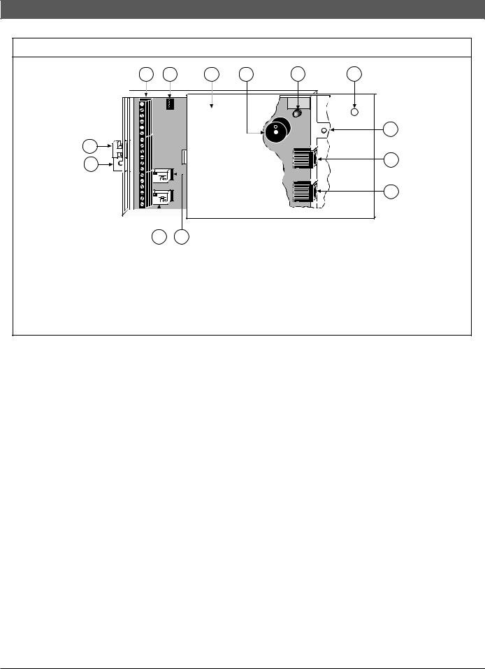
Figure 1: D2071A Control Panel
1 |
2 |
3 |
4 |
5 |
6 |
|
|
|
|
|
7 |
12 |
|
|
|
|
|
7 |
|
|
|
|
8 |
|
|
|
|
|
|
|
Aromat |
|
|
|
|
|
DS1E-M |
|
|
|
|
|
-DC12V |
|
|
|
|
|
AG20134408 |
|
|
|
|
|
JAPAN |
|
|
|
|
|
30830 BOTTOM VIEW |
|
|
|
|
|
Aromat |
|
|
|
9 |
|
DS1E-M |
|
|
|
|
|
-DC12V |
|
|
|
|
|
AG20134408 |
|
|
|
|
|
JAPAN |
|
|
|
|
|
30830 BOTTOM VIEW |
|
|
|
|
|
|
|
|
|
|
|
|
|
|
|
|
|
|
|
|
10 |
|
|
|
|
|
11 |
|
|
|
||||
|
|
|
|
|
|
|
|
||
1 |
- |
Terminal strip |
7 - Mounting tab |
||||||
2 - |
Programmer connector (J3) |
8 - |
Alternate modular telephone jack (J2) |
||||||
3 - |
D2071A Enclosure Cover |
9 - |
Primary modular telephone jack (J1) |
||||||
4 - Phone Line Trouble Buzzer |
10 |
- Phone Line Trouble Relay socket (K5) |
|||||||
5 |
- Phone Line Trouble LED |
11 |
- Initiating Circuit Alarm Relay socket (K6) |
||||||
6 |
- |
LED hole |
12 |
- Strain relief tab |
|||||
1.8.5Phone Line Trouble LED
This yellow Phone Line Trouble LED (Item 5 in Figure 1) is visible through the top of the enclosure at the upper right corner (Item 6 in Figure 1). This LED lights when the control panel detects telephone line trouble on either the primary or secondary telephone line, when there is a communication failure, and briefly on powerup.
1.8.6Mounting Tabs
Mounting tabs (Item 7 in Figure 1) are located on each end of the D2071A to provide a way to mount the D2071A with screws. You can also use the adhesive strips to mount the D2071A.
1.8.7Alternate Modular Telephone Jack
The alternate telephone jack (Item 8 in Figure 1) connects the D2071A to an alternate telephone line for transmitting to the receiver. If the D2071A fails to contact the receiver after two attempts on the primary line, it switches to the alternate line.
1.8.8Primary Modular Telephone Jack
The primary telephone jack (Item 9 in Figure 1) connects the D2071A to the primary telephone line for transmitting to the receiver.
1.8.9Phone Line Trouble Relay (K5)
Install a D136 Relay in this socket when using the optional Phone Line Trouble Relay (Item 10 in Figure 1) for Terminals 13 to 15. This relay activates when telephone line trouble is detected on the primary or secondary telephone line, communication failure occurs, and briefly at powerup.
1.8.10Initiating Circuit Alarm Relay (K6)
Install a D136 Relay in this socket when using the optional Initiating Circuit Alarm Relay (Item 11 in Figure 1) for Terminals 16 to 18. This relay activates when the initiating circuit is in an alarm condition.
1.8.11Strain Relief Tab
The strain relief tab (Item 12 in Figure 1) prevents unnecessary strain on the connections to the D2071A. Use the cable tie (included) to secure all wire running from the D2071A to the tab.
Bosch | 09/04 | 74-06200-000-F |
7 |

D2071A | Operations & Installation Guide | 2.0 Installation
2.0Installation
Some terminals are wired differently for the stand-alone (Figure 2) and slave applications (Figure 3 on page 9).
When you are using the D2071AC, mount the D4103R Enclosure and have a qualified electrician connect a 110 VAC or 120 VAC power source to the black and white leads on the transformer. Before beginning the D2071A installation, ensure the power source is turned off.
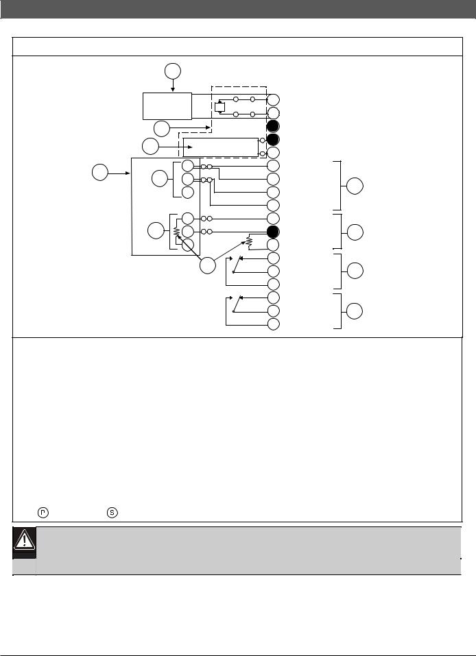
Figure 2: Stand-Alone Installation
10
P
S
|
1 |
S |
P |
|
1 |
|
|
|
|||
|
|
|
|
2 |
|
|
|
S |
P |
|
|
|
|
|
|
|
3 |
|
3 |
|
- |
P |
4 |
|
|
+ |
|
5 |
|
|
|
|
P |
||
|
5 |
P |
|
|
6 |
|
|
|
|
|
|
|
|
S |
|
|
7 |
|
|
6 |
|
|
8 |
|
5 |
P |
|
|
|
|
|
|
|
9 |
|
|
|
S |
|
|
|
|
9 |
|
8 |
|
|
|
P |
|
|
|
|
|
|
|
|
10 |
|
10 |
|
10 |
|
|
|
P |
|
|
11 |
||
|
|
S |
|
|
|
11 |
S |
11 |
|
|
12 |
|
|
P |
|
|
|
|
11 |
11 |
NC |
13 |
|
|
|
|
|
||
|
|
|
C |
|
14 |
|
|
|
|
|
|
|
|
|
NO |
15 |
|
|
|
|
NC |
|
16 |
|
|
|
C |
|
17 |
|
|
|
|
|
|
|
|
|
NO |
18 |
|
12 VAC, 20 VA, 60 Hz
12 VAC, 20 VA, 60 Hz
EARTH GND
BATTERY –
2
BATTERY + INITIATING A1 –
INITIATING A2 –
4
INITIATING B1 +
INITIATING B2 +
SUPERVISORY HI |
|
|
|
SUPERVISORY LO |
|
7 |
|
|
|||
SUPERVISORY HI |
|
|
|
|
|
|
|
TBL RELAY NC |
|
|
|
TBL RELAY COM |
|
12 |
|
|
|||
TBL RELAY NO |
|
|
|
|
|
|
|
ALARM RELAY NC |
|
|
|
ALARM RELAY COM |
|
13 |
|
|
|||
ALARM RELAY NO |
|
|
|
1 - 12 VAC, 20 VA transformer
2 - Maximum charging current 300 mA
3 - Battery backup (D126 [12 V, 7 Ah] or D1219 [12 V, 2.3 Ah])
4 - Alarm initiating circuit
5 - Open = Trouble
6 - Short = Alarm
7 - Supervisory circuits
8 - Mode 3 (Alarm [short] = 0 VDC to 1.7 VDC; Normal [resistive] = 1.9 VDC to 5.8 VDC;
Trouble [open] = 6.0 VDC to 10.2 VDC)
9 - Mode 2 (Normal = 0 VDC to 1.5 VDC; Alarm [resistive] = 1.8 VDC to 9.0 VDC;
Trouble [open] = 9.3 VDC to 13.0 VDC)
10 - Mode 1 (Normal = 0 VDC to 1.5 VDC; Alarm [open] = 1.8 VDC to 13.0 VDC)
11- 1.8 kΩ EOL resistor
12- Phone Trouble Relay (maximum rating 2 A at 30 VDC)
13- Initiating Circuit Alarm Relay (maximum rating 2A at 30 VDC)
Note:  = Power limited;
  = Supervised
8 |
Bosch | 09/04 | 74-06200-000-F |
D2071A | Operations & Installation Guide | 2.0 Installation
Figure 3: Slave Communicator Installation
1
|
|
+ |
|
S |
P |
|
1 |
12 VAC, 20 VA, 60 Hz, OR + 24 VDC |
|
|
|
|
|
|
|
|
|||
|
|
- |
|
S |
P |
|
2 |
12 VAC, 20 VA, 60 Hz, OR – 24 VDC |
|
|
|
|
|
|
|
|
|
|
|
|
2 |
|
|
|
|
|
3 |
EARTH GND |
|
|
3 |
|
|
|
- |
P |
4 |
BATTERY – |
|
|
|
|
|
+ |
|
5 |
BATTERY + |
|
|
|
|
|
|
|
P |
|
|||
|
6 |
N |
P |
S |
|
|
6 |
INITIATING A1 – |
|
|
|
|
|
|
|
|
|
|
|
|
5 |
C |
P |
S |
|
|
7 |
INITIATING A2 – |
4 |
|
|
N |
|
|
|
|
8 |
INITIATING B1 + |
|
|
|
|
|
|
|
|
|||
|
|
|
|
|
|
|
9 |
INITIATING B2 + |
|
|
|
N |
P |
S |
|
|
10 SUPERVISORY HI |
|
|
|
|
|
|
|
|
|
|
||
|
8 |
C |
P |
S |
|
|
11 SUPERVISORY LO |
7 |
|
|
|
N |
|
|
|
|
12 SUPERVISORY HI |
|
|
|
|
|
9 |
NC |
13 TBL RELAY NC |
|
|||
|
|
|
C |
|
14 TBL RELAY COM |
10 |
|||
|
|
|
|
|
|
||||
|
|
|
|
|
|
|
|||
|
|
|
|
|
NO |
15 TBL RELAY NO |
|
||
|
|
|
|
|
NC |
16 ALARM RELAY NC |
|
||
|
|
|
|
|
C |
|
17 ALARM RELAY COM |
11 |
|
|
|
|
|
|
|
|
|||
|
|
|
|
|
NO |
18 ALARM RELAY NO |
|
||
1 - |
Primary power supply (24 VDC supply from UL Listed FACP or 12 VAC, 20 VA transformer) |
||||||||
2 - |
Alternate power supply |
|
|
|
|
|
|
|
|
3 - |
D126 Battery (12 V, 7 Ah) or D1219 Battery (12 V, 2.3 Ah) |
|
|
|
|||||
4 - Alarm initiating circuit (Trouble = open on Terminals 6, 7, 8, and 9; Alarm = short from Terminals 6 and 7 to
Terminals 8 and 9)
5 - Dry Closure Alarm Indicator Relay (Form “A” Normally Open)
6 - FACP
7 - Supervisory circuits: Mode 3 (Alarm [short] = 0 VDC to 1.7 VDC; Normal [resistive] = 1.9 VDC to 5.8 VDC; Trouble [open] = 6.0 VDC to 10.2 VDC)
8 - Dry Closure Trouble Indicator Relay (Form “A” Normally Open)
9 - 1.8 kΩ EOL resistor
10 |
- Phone Trouble Relay (maximum rating 2 A at 30 VDC) |
||
11 |
- Initiating Circuit Alarm Relay (maximum rating 2A at 30 VDC) |
||
Note: |
= Power limited; |
= Supervised |
|
1. Do not connect earth ground when connected to a 24 VDC power supply.
2. Do not connect a battery when connected to a 24 VDC power supply (maximum charging current of 300 mA).
Bosch | 09/04 | 74-06200-000-F |
9 |
 Loading...