


User's
Manual
 3 Series
Foundation Fieldbus Communication Type
Coriolis Mass Flow and Density Meter
Integral Type RCCT3
Remote Type RCCF31 + RCCS3
IM 01R04B05-00E-E, additional manual to IM 01R04B04-00x-E
Rota Yokogawa GmbH & Co. KG
Rheinstr. 8
D-79664 Wehr
Germany
IM 01R04B05-00E-E ©Copyright July 2005 (Rü) 3rd edition, July 2010 (Rü)

Blank Page

|
|
|
|
|
CONTENTS |
|
|
|
|
Contents |
|
1. |
Introduction.................................................................................. |
|
1-1 |
||
|
1.1 |
Using the Coriolis Flowmeter Safely............................................................ |
1-2 |
||
|
1.2 |
Warranty........................................................................................................... |
|
1-3 |
|
|
1.3 |
Instruction according EMC............................................................................ |
1-3 |
||
|
1.4 |
ATEX Documentation...................................................................................... |
1-4 |
||
|
1.5 |
Disposal, Cleaning and Return...................................................................... |
1-5 |
||
2. AMPLIFIER FOR FOUNDATION FIELDBUS COMMUNICATION..... |
2-1 |
||||
3. ABOUT Foundation FIELDBUS..................................................... |
3-1 |
||||
|
3.1 |
Outline.............................................................................................................. |
|
3-1 |
|
|
3.2 |
Internal Structure of Rotamass.................................................................. |
3-1 |
||
|
3.2.1 |
System/Network Management VFD............................................................................ |
3-1 |
||
|
3.2.2 |
Function Block VFD............................................................................................. |
3-1 |
||
|
3.3 |
Logical Structure of Each Block................................................................... |
3-2 |
||
|
3.4 |
Wiring System Configuration......................................................................... |
3-2 |
||
4. |
GETTING STARTED............................................................................ |
4-1 |
|||
|
4.1 |
Connection of Devices........................................................................................... |
4-1 |
||
|
4.2 |
Host Setting..................................................................................................... |
|
4-3 |
|
|
4.3 |
Power-on of |
ROTAMASS and Bus....................................................... |
4-3 |
|
|
4.4 |
Integration of DD............................................................................................. |
|
4-3 |
|
|
4.5 |
Reading the |
Parameters............................................................... |
4-4 |
|
|
4.6 |
Continuous Record of Values........................................................................ |
4-4 |
||
|
4.7 |
Generation of Alarm........................................................................................ |
4-4 |
||
All Rights Reserved. Copyright © 2005, Rota Yokogawa |
IM 01R04B05-00E-E 3rd edition July 30, 2010 -00 |

CONTENTS |
|
|
||
5. CONFIGURATION................................................................................. |
5-1 |
|||
|
5.1 |
Network Design............................................................................................... |
5-1 |
|
|
5.2 |
Network Definition........................................................................................... |
5-1 |
|
|
5.3 |
Function Block Link Definitions.................................................................... |
5-2 |
|
|
5.4 |
Setting of Tags and Addresses.................................................................................... |
5-3 |
|
|
5.5 |
Communication Setting.................................................................................. |
5-4 |
|
|
5.5.1 |
VCR Setting........................................................................................................... |
5-4 |
|
|
5.5.2 |
Function Block Execution Control......................................................................... |
5-5 |
|
|
5.6 |
Block Setting................................................................................................... |
5-5 |
|
|
5.6.1 |
Link Objects.......................................................................................................... |
5-5 |
|
|
5.6.2 |
Trend Objects....................................................................................................... |
5-6 |
|
|
5.6.3 |
View Objects......................................................................................................... |
5-6 |
|
|
5.6.4 |
AI Function Block Parameters.......................................................................... |
5-16 |
|
|
5.6.5 |
Transducer Block Parameters.......................................................................... |
5-18 |
|
6. |
IN-PROCESS OPERATION................................................................. |
6-1 |
||
|
6.1 |
Mode Transition............................................................................................... |
6-1 |
|
|
6.2 |
Generation of Alarm........................................................................................ |
6-1 |
|
|
6.2.1 |
Indication of Alarm............................................................................................... |
6-1 |
|
|
6.2.2 |
Alarms and Events............................................................................................... |
6-3 |
|
|
6.3 |
Simulation Function........................................................................................ |
6-3 |
|
7. |
DEVICE STATUS................................................................................. |
7-1 |
||
8. |
GENERAL SPECIFICATIONS............................................................. |
8-1 |
||
IM 01R04B05-00E-E 3rd edition July 30, 2010 -00 |
ii |
All Rights Reserved. Copyright © 2005, Rota Yokogawa |

|
|
|
|
CONTENTS |
9. Explosion protected type ................................................. |
9-1 |
|||
instruments......................................................................................... |
||||
9.1 |
ATEX ................................................................................................................ |
9-1 |
||
9.1.1 |
Technical Data...................................................................................................... |
9-1 |
||
9.1.2 |
Installation............................................................................................................. |
9-3 |
||
9.1.3 |
Operation............................................................................................................... |
9-6 |
||
9.1.4 |
Maintenance and repair....................................................................................... |
9-6 |
||
9.1.5 |
Ex-relevant marking on name plate................................................................... |
9-6 |
||
9.2 |
FM ..................................................................................................................... |
|
9-9 |
|
9.2.1 |
Technical Data...................................................................................................... |
9-9 |
||
9.2.4 |
Ex-relevant marking on name plate................................................................. |
9-13 |
||
9.3 |
IECEx .............................................................................................................. |
9-17 |
||
9.3.1 |
Technical Data.................................................................................................... |
9-17 |
||
9.3.2 |
Installation........................................................................................................... |
9-20 |
||
9.3.3 |
Operation............................................................................................................. |
9-21 |
||
9.3.4 |
Maintenance and repair..................................................................................... |
9-21 |
||
9.3.5 |
Ex-relevant marking on name plate................................................................. |
9-21 |
||
9.3.6 |
I.S. fieldbus system complying with FISCO (only /EF4)................................ |
9-23 |
||
9.4 |
INMETRO (Brazil) ........................................................................................... |
9-23 |
||
9.5 |
Gost Approval ................................................................................................ |
9-23 |
||
APPENDIX 1. LIST OF PARAMETERS FOR EACH BLOCK OF ROTA- |
||||
MASS |
........................................................................................................ |
|
|
A-1 |
A1.1 |
Resource Block............................................................................................ |
A-1 |
||
A1.2 |
Al Function Block........................................................................................ |
A-4 |
||
A1.3 |
Transducer Block........................................................................................ |
A-8 |
||
A1.4.1 ................................................Schematic Diagram of Integrator Block |
A-16 |
|||
A1.4.2 ...................................................................................Input process Section |
A-17 |
|||
A1.4.2.1 ...............................................................Determining Input Value Statuses |
A-17 |
|||
A1.4.2.2 .......................................................................................Converting the Rate |
A-17 |
|||
A1.4.2.3 .............................................................................Converting Accumulation |
A-18 |
|||
All Rights Reserved. Copyright © 2005, Rota Yokogawa |
iii |
IM 01R04B05-00E-E 3rd edition July 30, 2010 -00 |

CONTENTS |
|
|
A1.4.2.4 Determining the Input Flow Direction......................................................... |
A-18 |
|
A1.4.3 Adder......................................................................................................... |
A-18 |
|
A1.4.3.1 Status of Value after Addition...................................................................... |
A-18 |
|
A1.4.3.2 Addition........................................................................................................... |
A-19 |
|
A1.4.4 Integrator.................................................................................................. |
A-19 |
|
A1.4.5 Output Process........................................................................................ |
A-21 |
|
A1.4.5.1 Status Determination..................................................................................... |
A-21 |
|
A1.4.5.2 Determining the Output Value...................................................................... |
A-22 |
|
A1.4.5.3 Mode Handling............................................................................................... |
A-23 |
|
A1.4.6 Reset......................................................................................................... |
A-23 |
|
A1.4.6.1 Reset Trigger.................................................................................................. |
A-23 |
|
A1.4.6.2 Reset Timing.................................................................................................. |
A-23 |
|
A1.4.6.3 Reset Process................................................................................................ |
A-24 |
|
A1.4.7 List of Integrator Block Parameters...................................................... |
A-25 |
|
APPENDIX 2. APPLICATION, SETTING AND CHANGE OF BASIC |
A-27 |
|
PARAMETERS....................................................................................... |
||
A2.1 |
Applications and Selection of Basic Parameters................................... |
A-27 |
A2.2 |
Setting and Change of Basic Parameters............................................... |
A-28 |
A2.3 |
Setting the AI Function Blocks................................................................ |
A-28 |
A2.4 |
Setting the Transducer Block.................................................................. |
A-30 |
APPENDIX 3. OPERATION OF EACH PARAMETER IN FAILURE |
A-33 |
|
MODE..................................................................................................... |
|
|
APPENDIX 4. FUNCTION DIAGRAMS OF FUNCTION BLOCKS..... |
A-45 |
|
A4.1 |
AI Function Block...................................................................................... |
A-45 |
APPENDIX 5. PID BLOCK................................................................... |
A-47 |
|
A5.1 |
Function Diagram...................................................................................... |
A-47 |
A5.2 |
Functions of PID Block............................................................................. |
A-47 |
A5.3 |
Parameters of PID Block........................................................................... |
A-48 |
A5.4 |
PID Computation Details........................................................................... |
A-50 |
A5.4.1 PV-proportional and -derivative Type PID (I-PD) Control Algorithm versus |
||
PV-derivative Type PID (PI-D) Control Algorithm..................................................... |
A-50 |
|
IM 01R04B05-00E-E 3rd edition July 30, 2010 -00 |
iv |
All Rights Reserved. Copyright © 2005, Rota Yokogawa |

|
|
|
CONTENTS |
A5.4.2 |
PID Control Parameters.................................................................................. |
A-50 |
|
A5.5 Control Output............................................................................................ |
A-50 |
||
A5.5.1 |
Velocity Type Output Action.......................................................................... |
A-50 |
|
A5.6 Direction of Control Action........................................................................ |
A-50 |
||
A5.7 Control Action Bypass............................................................................... |
A-51 |
||
A5.8 |
Feed-forward.............................................................................................. |
A-51 |
|
A5.9 Block Modes................................................................................................ |
A-51 |
||
A5.9.1 |
Mode Transitions............................................................................................. |
A-52 |
|
A5.10 |
Bumpless Transfer.................................................................................. |
A-52 |
|
A5.11 |
Setpoint Limiters..................................................................................... |
A-52 |
|
A5.11.1 |
When PID Block Is in AUTO Mode.............................................................. |
A-52 |
|
A5.11.2 |
When PID Block Is in CAS or RCAS Mode................................................. |
A-52 |
|
A5.12 |
External-output Tracking........................................................................ |
A-53 |
|
A5.13 |
Measured-value Tracking........................................................................ |
A-53 |
|
A5.13.1 |
CONTROL_OPTS........................................................................................... |
A-53 |
|
A5.14 |
Initialization and Manual Fallback (IMAN)............................................. |
A-53 |
|
A5.15 |
Manual Fallback....................................................................................... |
A-54 |
|
A5.15.1 |
STATUS_OPTS............................................................................................... |
A-54 |
|
A5.16 |
Auto Fallback........................................................................................... |
A-54 |
|
A5.17 |
Mode Shedding upon Computer Failure............................................... |
A-54 |
|
A5.17.1 |
SHED_OPT...................................................................................................... |
A-54 |
|
A5.18 |
Alarms....................................................................................................... |
A-55 |
|
A5.18.1 |
Block Alarm (BLOCK_ALM).......................................................................... |
A-55 |
|
A5.19 |
Example of Block Connections.............................................................. |
A-55 |
|
All Rights Reserved. Copyright © 2005, Rota Yokogawa |
IM 01R04B05-00E-E 3rd edition July 30, 2010 -00 |

CONTENTS |
|
|
|
APPENDIX 6. SOFTWARE DOWNLOAD............................................. |
A-57 |
||
A6.1 |
Benefits of Software Download................................................................. |
A-57 |
|
A6.2 |
Specifications.............................................................................................. |
A-57 |
|
A6.3 |
Preparations for Software Downloading....................................................... |
A-57 |
|
A6.4 |
Software Download Sequence.................................................................. |
A-58 |
|
A6.5 |
Download Files............................................................................................ |
A-58 |
|
A6.6 |
Steps after Activating a Field Device........................................................ |
A-59 |
|
A6.7 |
Troubleshooting.......................................................................................... |
A-60 |
|
A6.8 |
Resource Block’s Parameters Relating to Software Download............ |
A-60 |
|
A6.9 |
System/Network Management VFD Parameters Relating to Software Down- |
||
load........................................................................................................................ |
|
|
A-62 |
A6.10 Comments on System/Network Management VFD Parameters Relating to |
|||
Software Download............................................................................................. |
A-63 |
||
APPENDIX 7. LINK MASTER FUNCTIONS........................................ |
A-65 |
||
A7.1 |
Link Active Scheduler............................................................................... |
A-65 |
|
A7.2 |
Link Master................................................................................................. |
A-65 |
|
A7.3 |
Transfer of LAS.......................................................................................... |
A-66 |
|
A7.4 |
LM Functions............................................................................................. |
A-67 |
|
A7.5 |
LM Parameters........................................................................................... |
A-68 |
|
A7.5.1 |
LM Parameter List........................................................................................... |
A-68 |
|
A7.5.2 |
Descriptions for LM Parameters.................................................................... |
A-70 |
|
A7.6 |
FAQs........................................................................................................... |
A-72 |
|
APPENDIX 8. DEVICEVIEWER WINDOW EXECUTED FROM Fieldmate |
|||
AND PRM (Plant Resource Manager) ................................................ |
A-75 |
||
IM 01R04B05-00E-E 3rd edition July 30, 2010 -00 |
vi |
All Rights Reserved. Copyright © 2005, Rota Yokogawa |
1. Introduction
This instrument has been adjusted at the factory before shipment.
To ensure correct use of the instrument, please read this manual thoroughly and fully understand how to operate the instrument before operating it.
NOTE
This manual describes the hardware and software configurations of the Rotamass Coriolis Massflowmeter.
Regarding This User's Manual
•This manual should be provided to the end user.
•Before use, read this manual thoroughly to comprehend its contents.
•The contents of this manual may be changed without prior notice.
•All rights are reserved. No part of this manual may be reproduced in any form without Yokogawa's written permission.
•Yokogawa makes no warranty of any kind with regard to this material, including, but not limited to, implied warranties of merchantability and suitability for a particular purpose.
•All reasonable effort has been made to ensure the accuracy of the contents of this manual. However, if any errors or omissions are found, please inform Yokogawa.
•Yokogawa assumes no responsibilities for this product except as stated in the warranty.
•Please note that this user's manual may not be revised for any specification changes, construction changes or operating part changes that are not considered to affect function or performance.
•If the customer or any third party is harmed by the use of this product, Yokogawa assumes no responsibility for any such harm owing to any defects in the product which were not predictable, or for any indirect damages.
1. INTRODUCTION
Safety and Modification Precautions
•The following general safety precautions must be observed during all phases of operation, service, and repair of this instrument. Failure to comply with these precautions or with specific WARNINGS given elsewhere in this manual violates safety standards of design, manufacture, and intended use of the instrument. Yokogawa assumes no liability for the customer's failure to comply with these requirements. If this instrument is used in a manner not specified in this manual, the protection provided by this instrument may be impaired.
•The following safety symbol marks are used in this user's manual and instrument.
WARNING
A WARNING sign denotes a hazard. It calls attention to procedure, practice, condition or the like, which, if not correctly performed or adhered to, could result in injury or death of personnel.
CAUTION
A CAUTION sign denotes a hazard. It calls attention to procedure, practice, condition or the like, which, if not correctly performed or adhered to, could result in damage to or destruction of part or all of the product.
IMPORTANT
An IMPORTANT sign denotes that attention is required to avoid damage to the instrument or system failure.
NOTE
A NOTE sign denotes information necessary for essential understanding of operation and features.
All Rights Reserved. Copyright © 2005, Rota Yokogawa |
1-1 |
IM 01R04B05-00E-E 3rd edition July 30, 2010-00 |

1. INTRODUCTION
 Protective grounding terminal
Functional grounding terminal
(This terminal should not be used as a protective grounding terminal.)
 Alternating current
 Direct current
1.1Using the Coriolis Flowmeter Safely
WARNING
(1) Installation
•Installation of the Coriolis flowmeter must be performed by expert engineer or skilled personnel. No operator shall be permitted to perform procedures relating to installation.
•The Coriolis flowmeter is a heavy instrument. Be careful that no damage is caused to personnel through accidentally dropping it, or by exerting excessive force on the Coriolis flowmeter. When moving the Coriolis flowmeter, always use a trolley and have at least two people carry it.
•When the Coriolis flowmeter is processing hot fluids, the instrument itself may become extremely hot. Take sufficient care not to get burnt.
•Where the fluid being processed is a toxic substance, avoid contact with the fluid and avoid inhaling any residual gas, even after the instrument has been taken off the line for maintenance and so forth.
•All procedures relating to installation must comply with the electrical code of the country where it is used.
(2) Wiring
•The wiring of the Coriolis flowmeter must be performed by expert engineer or skilled personnel. No operator shall be permitted to perform procedures relating to wiring.
•When connecting the wiring, check that the supply voltage is within the range of the voltage specified for this instrument before connecting the power cable. In addition, check that no voltage is applied to the power cable before connecting the wiring.
•The protective grounding must be connected securely at the terminal with the  mark to avoid danger to personnel.
(3) Operation
•Do not open the cover until the power has been off for at least 10 minutes. Only expert engineer or skilled personnel are permitted to open the cover.
(4) Maintenance
•Maintenance on the Coriolis flowmeter should be performed by expert engineer or skilled personnel. No operator shall be permitted to perform any operations relating to maintenance.
•Always conform to maintenance procedures outlined in this manual. If necessary, contact Yokogawa.
•Care should be taken to prevent the build up of dirt, dust or other substances on the display panel glass or data plate. If these surfaces do get dirty, wipe them clean with a soft dry cloth.
(5) European Pressure Equipment Directive (PED)
• When using the instrument as a PED-compliant product, be sure to read Chapter 10 before use.
(6) Hazardous Duty Type Instruments
• For explosion proof type instruments the description in chapter 9 "EXPLOSION PROTECTED TYPE INSTRUMENT" has priority to the other descriptions in this instruction manual.
•All instruction manuals for ATEX Ex related products are available in English, German and French. Should you require Ex related instructions in your local language, you should contact
your nearest Yokogawa office or representative.
•Only trained personal should install and maintain instruments in hazardous areas.
•The protective grounding terminal  must be connected to a suitable IS grounding system.
•Avoid mechanical generated sparks while working on the equipment and peripherally devices in hazardous areas.
FOUNDATION is a registered trademark of Fieldbus FOUNDATION.
IM 01R04B05-00E-E 3rd edition July 30, 2010 -00 |
1-2 |
All Rights Reserved. Copyright © 2005, Rota Yokogawa |
1.2 Warranty
•The warranty terms of this instrument that are guaranteed are described in the quotation. We will make any repairs that may become necessary during the guaranteed term free of charge.
•Please contact our sales office if this instrument requires repair.
•If the instrument is faulty, contact us with complete details about the problem and the length of time it has been faulty, and state the model and serial number. We would appreciate the inclusion of drawings or additional information.
•The results of our examination will determine whether the meter will be repaired free of charge or on an at-cost basis.
The guarantee will not apply in the following cases:
•Damage due to negligence or insufficient maintenance on the part of the customer.
•Problems or damage resulting from handling, operation or storage that violates the intended use and specifications.
•Problems that result from using or performing maintenance on the instrument in a location that does not comply with the installation location specified by Yokogawa.
•Problems or damage resulting from repairs or modifications not performed by Yokogawa or someone authorized by Yokogawa.
•Problems or damage resulting from inappropriate installation after delivery.
•Problems or damage resulting from disasters such as fires, earthquakes, storms, floods, or lightning strikes and external causes.
1.3 Instruction according EMC
The Rotamass Coriolis flowmeter is conform to the European EMC Guideline and fulfills the following standards:
EN 61326-1: 2006;
EN 61326-2-3: 2006;
EN 61000-3-2: 2006;
EN 61000-3-3: 1995+A1+A2
Rotamass is a class A product and should be used and installed properly according to the EMC Class A requirements.
1. INTRODUCTION
Restriction on Use of Radio Transceiver :
IMPORTANT
Although the products has been designed to resist high frequency electrical noise, if a radio transceiver is used near the flowmeter or its external wiring, the transmitter may be affected by high frequency noise pickup. To test for such effects, bring the transceiver in use slowly from a distance of several meters from the flowmeter, and observe the measurement loop for noise effects. Thereafter, always use the transceiver outside the area affected by noise.
Installation
CAUTION
The function ground terminal or the PE-terminal have to be connected to protective ground to ensure electro-magnetic interference protection.
To ensure the EMC specifications the following measures must be carried out :
1.Put the power cables through the ferrite core clamp before connecting to the terminals as shown in chapter ´ Installation ´(Power supply wiring).
2.Put the I/O- cables through the ferrite core clamp before connecting to the terminals as shown in chapter ´ Installation ´(Power supply wiring).
3.Connect protective ground conductor of power supply to PE-terminal in the terminal box (see chapter ´ Installation ´(Power supply wiring).
4.In case of Explosion proof type instrument, further requirements are described in chapter 9 “EXPLOSION PROTECTED TYPE INSTRUMENTS”. The description in this chapter is prior to other descriptions in this instruction manual.
All Rights Reserved. Copyright © 2005, Rota Yokogawa |
1-3 |
IM 01R04B05-00E-E 3rd edition July 30, 2010-00 |

1. INTRODUCTION
1.4 ATEX Documentation
This is only applicable to the countries in European Union.
GB |
SK |
CZ
DK
I |
LT |
E |
LV |
EST
NL
PL
SF


 SLO P
SLO P 


H
F
BG
D
RO
S
M
GR
IM 01R04B05-00E-E 3rd edition July 30, 2010 -00 |
1-4 |
All Rights Reserved. Copyright © 2005, Rota Yokogawa |

1.5Disposal, Cleaning and Return
For safe use
WARNING
If the process fluid is harmful to personnel, handle the instrument carefully even after it has been removed from the process line for maintenance or other purposes. Exercise extreme care to prevent the fluid from coming into contact with human skin and to avoid inhaling any residual gas. Before sending it to the Seller for examination and/or repair please clean the instrument thoroughly and make sure, that no harmful chemicals are in or at the meter. If the instrument contains unknown fluids the Seller will send it back to the Purchaser
for cleaning on their cost.
WARNING
ROTAMASS might be heavy instruments. Please give attention to prevent that persons are not injured by carrying or installing. It is preferable when carrying the instrument to use a cart and be done by two or more persons. When removing the instrument from hazardous processes, avoid contact with the fluid and the interior of the meter.
Warranty
The warranty of the instruments shall cover the period noted on the quotation presented to the purchaser at the time of purchase. The Seller shall repair the instrument free of charge when the failure occurred during the warranty period.
All inquiries on instrument failure should be directed to the Seller’s sales representative from whom you purchased the instrument or your nearest sales office of the Seller.
Should the instrument fail, contact the Seller, specifying the model and instrument number of the product in question. Be specific in describing details on the failure and the process in which
1. INTRODUCTION
the failure occurred. It will be helpful if schematic diagrams and/or records of data are attached to the failed instrument. Whether or not the failed instrument should be repaired free of charge shall be left solely to the discretion of the Seller as a result of an inspection by the Seller.
The Purchaser shall not be entitled to receive repair services from the Seller free of charge, even during the warranty period, if the malfunction or damage is due to improper and/or inadequate maintenance of the instrument in question by the Purchaser handling, use or storage of the instrument in question beyond the design and/or specifications requirements, use of the instrument in question in a location no conforming to the conditions specified in the Seller’s General Specification or Instruction Manual retrofitting and/or repair by an other party than the Seller or a party to whom the Seller has entrusted repair services. improper relocation of the instrument in question after delivery reason of force measure such as fires, earthquakes, storms/ floods, thunder/lightning, or other reasons not attributable to the instrument in question.
For disposal and recycling please refer to your national regulations.
Please find following help. After remove of all products rests the instruments can be disassembled and the parts treated different.
Naming: R = recycling, D = disposal, Sd = special disposal, Na = not applicable
Name |
Body |
|
Converter |
Cover with |
Elec- |
|||
of |
|
|
|
housing |
window |
tron- |
||
product |
|
|
|
|
|
|
|
ics |
Rota- |
SS |
|
R |
Al |
R |
Al + |
D |
Sd |
mass |
|
|
|
|
|
Glass |
|
|
In case of return of flowmeters to Yokogawa for testing or repair purposes please fillout one of the following forms and send it with the equipment to YOKOGAWA.
All Rights Reserved. Copyright © 2005, Rota Yokogawa |
1-5 |
IM 01R04B05-00E-E 3rd edition July 30, 2010-00 |

1. INTRODUCTION
Receiver : |
Sender : |
Delivery Note (for EU-Countries) |
Date : |
|
|
||
Ref. REPAIR for serial no. __________________________ |
|
||||
We are sending following type of article |
|
|
|
||
via forwarding agent : Yusen Air ; Raunheim/Frankfurt |
|
|
|||
Item Article |
|
|
|
Unit Price |
Total Price |
Type (MS-Code) |
|
|
|
|
|
________________________________ |
€ __________ |
€__________ |
|||
|
|
|
|
|
(nominal value) |
Charges for airworthy packing |
|
|
|
||
and delivery FOB |
|
|
|
€___________ |
|
Total value |
|
|
|
€ ___________ |
|
Value for customs purpose only |
|
|
€ _________ |
||
|
|
|
|
|
(current value) |
Gross weight . |
_____________________kg |
|
|||
Net weight : |
_____________________kg |
|
|||
Customs Tariff No. : |
_____________________ |
|
|
||
Country og origin : |
Federal Republic of Germany |
|
|||
Delivery note 2-fold accompanis the goods |
|
|
|||
|
|
|
SPECIMEN Certificate |
|
|
Company : |
________________________ |
Address : |
______________________ |
||
Department : |
________________________ |
Name : |
______________________ |
||
Telephone : |
________________________ |
Fax : |
______________________ |
||
The attached flowmeter : |
|
|
|
|
|
|
|
|
|
Type : ______________________________ |
|
Orderor Serial No. |
___________ |
||||||
has been operated with following liquids:___________________________________________ |
|||||||||
Because the liquid is |
|
water-endangering |
|
toxic |
|
caustic |
|
|
flammable |
|
|
|
|
|
|||||
we have |
|
|
|
|
|
|
|
|
|
checked, that all cavities in the flowmeter are free from such substances
flushed out and neutralised all cavities in the flowmeter
Please check applicable description
We confirm that there is no risk to man or enviroment through any residual liquid containes in this flowmeter.
Date : _____________________ |
Signature : _______________________ |
Company stamp:
IM 01R04B05-00E-E 3rd edition July 30, 2010 -00 |
1-6 |
All Rights Reserved. Copyright © 2005, Rota Yokogawa |

1. INTRODUCTION
Receiver : |
Sender : |
PROFORMA INVOICE (for Third-party-Countries) |
|
Date : |
||
Ref. REPAIR for serial no. __________________________ |
|
|||
We are sending following type of article |
|
|
||
via forwarding agent : Yusen Air ; Raunheim/Frankfurt |
|
|
||
Item Article |
|
|
Unit Price |
Total Price |
Type (MS-Code) |
|
|
|
|
________________________________ |
€ __________ |
€__________ |
||
|
|
|
|
(nominal value) |
Charges for airworthy packing |
|
|
||
and delivery FOB |
|
|
€___________ |
|
Total value |
|
|
€ ___________ |
|
Value for customs purpose only |
|
€ _________ |
||
|
|
|
|
(current value) |
Gross weight . |
_____________________kg |
|
||
Net weight : |
_____________________kg |
|
||
Customs Tariff No. : |
_____________________ |
|
|
|
Country og origin : |
Federal Republic of Germany |
|
||
Delivery note 2-fold accompanis the goods |
|
|
||
|
|
SPECIMEN Certificate |
|
|
Company : |
________________________ |
Address : |
______________________ |
|
Department : |
________________________ |
Name : |
______________________ |
|
Telephone : |
________________________ |
Fax : |
______________________ |
|
The attached flowmeter : |
|
|
|
|
|
|
|
|
|
Type : ______________________________ |
|
Orderor Serial No. |
___________ |
||||||
has been operated with following liquids:___________________________________________ |
|||||||||
Because the liquid is |
|
water-endangering |
|
toxic |
|
caustic |
|
|
flammable |
|
|
|
|
|
|||||
we have |
|
|
|
|
|
|
|
|
|
checked, that all cavities in the flowmeter are free from such substances
flushed out and neutralised all cavities in the flowmeter
Please check applicable description
We confirm that there is no risk to man or enviroment through any residual liquid containes in this flowmeter.
Date : _____________________ |
Signature : _______________________ |
Company stamp:
All Rights Reserved. Copyright © 2005, Rota Yokogawa |
1-7 |
IM 01R04B05-00E-E 3rd edition July 30, 2010-00 |

1. INTRODUCTION
Blank Page
IM 01R04B05-00E-E 3rd edition July 30, 2010 -00 |
1-8 |
All Rights Reserved. Copyright © 2005, Rota Yokogawa |
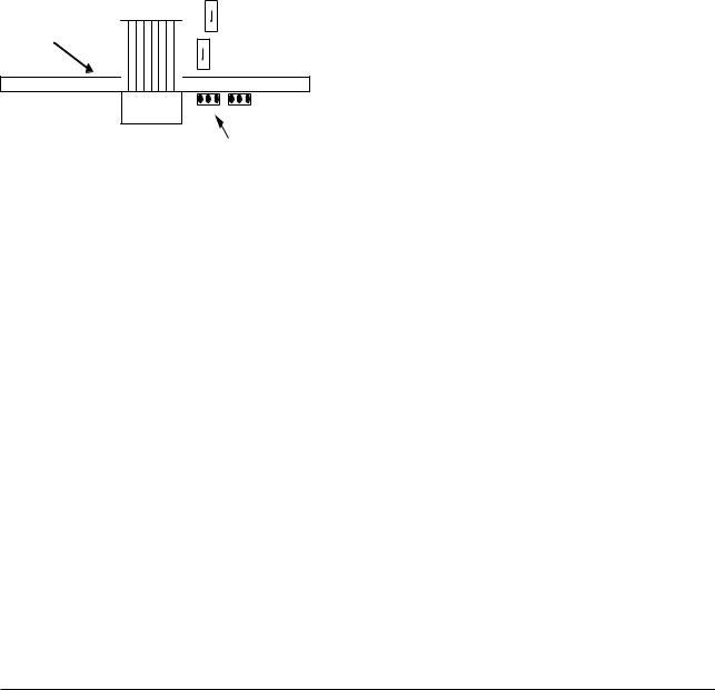
2. AMPLIFIER FOR FIELDBUS COMMUNICATION
2. AMPLIFIER FOR FOUNDATION FIELDBUS COMMUNICATION
Refer to IM 01R04B04-00E for the details of the amplifier. This section encompasses topics applicable to only the Fieldbus communication type.
(1)The Foundation Fieldbus communication type has no local key access function.
(2)The Foundation Fieldbus communication type has no HART terminal connection pin.
(3)The Foundation Fieldbus communication type has a simulation function. The SIMULATE_ENABLE jumper is mounted on the amplifier. Refer to Section 6.3, “Simulation Function” for details of the simulation function.
Std
FF Board
Simu
Cable to display
JP1 (Simulate_Enable)
F0201.EPS
Figure 2.1 Amplifier for Foundation Fieldbus Communication
All Rights Reserved. Copyright © 2005, Rota Yokogawa |
2-1 |
IM 01R04B05-00E-E 3rd edition July 30, 2010 -00 |

2. AMPLIFIER FOR FIELDBUS COMMUNICATION
Blank Page
IM 01R04B05-00E-E 3rd edition July 30, 2010 -00 |
2-2 |
All Rights Reserved. Copyright © 2005, Rota Yokogawa |

3. ABOUT FIELDBUS
3. ABOUT Foundation FIELDBUS
3.1 Outline
Fieldbus is a bi-directional digital communication protocol for field devices, which offers an advancement in implementation technologies for process control systems and is widely employed by numerous field devices.
The Foundation Fieldbus communication type of the Rotamass employs the specification standardized by the Foundation Fieldbus, and provides interoperability between Yokogawa devices and those produced by other manufacturers. Featuring 6 AI and two IT function blocks in each, the Fieldbus communication type’s software enables a flexible instrumentation system to be implemented.
For information on other features, engineering, design, construction work, startup and maintenance of Fieldbus, refer to “Fieldbus Technical Information” (TI 38K3A01-01E).
3.2 Internal Structure of
Rotamass
Each Rotamass contains two Virtual Field Devices (VFDs) that share the following functions.
3.2.1 System/Network Management VFD
•Sets node addresses and Physical Device tags (PD Tag) necessary for communication.
•Controls the execution of function blocks.
•Manages operation parameters and communication resources (Virtual Communication Relationship: VCR).
-Converts the flow sensor output to the process fluid density and transfers to an AI function block (AI3).
-Converts temperature sensor output to the process fluid temperature and transfers to an AI function block (AI4).
-Calculates the volumetric flow rate from the fluid density and the mass flow rate and transfers to an AI function block (AI2).
(3)AI function blocks (six)
•The AI blocks condition raw data from the transducer block, including scaling and damping (with a first-order lag), and allow input simulation.
•AI1 outputs mass flow rate signals, and AI2 outputs volumetric flow rate signals.
•AI3 outputs density signals, and AI4 outputs temperature signals.
•AI5 outputs concentration measurement signals (option), and AI6 outputs net flow rate signals (option).
(4)IT Integrator blocks (two)
•IT1 totalizes mass-, volume or net flow rate.
•IT2 totalizes mass-, volume or net flow rate.
(5)PID function block (optional)
•Performs the PID computation based on the deviation of the measured value from the setpoint.
3.2.2 Function Block VFD
(1)Resource (RS) block
•Manages the status of Rotamass hardware.
•Automatically informs the host of any detected faults or other problems.
(2)Transducer (TB) block
•Converts the flow sensor output to the mass flow rate signal and transfers to an AI function block (AI1).
All Rights Reserved. Copyright © 2005, Rota Yokogawa |
3-1 |
IM 01R04B05-00E-E 3rd edition July 30, 2010-00 |
3. ABOUT FIELDBUS
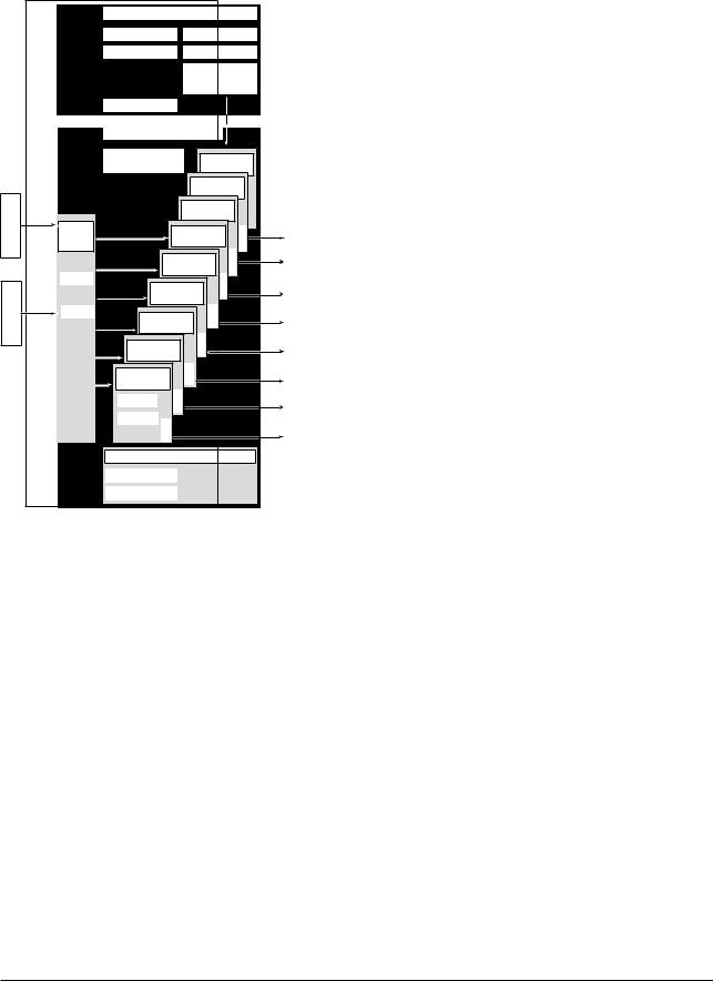
3.3Logical Structure of Each Block
|
Rotamass |
|
System/network management VFD |
|
||||||
|
|
|
|
|||||||
|
|
|
PD tag |
|
Communication parameters |
|
||||
|
|
|
Node address |
|
|
|
VCR |
|
|
|
|
|
|
|
|
|
Function block |
|
|||
|
|
|
|
|
execution schedule |
|
||||
|
|
|
Link master |
|
|
|
|
|
|
|
|
|
|
Function block VFD |
|
|
|
|
|||
|
|
|
Software download |
|
PID function block |
|
||||
|
|
|
function (optional) |
|
|
(optional) |
|
|
||
|
|
|
|
|
|
IT 2 Integrator |
|
|
||
|
|
|
|
|
|
|
block |
|
|
|
Coils |
Sensor |
|
|
|
IT 1 Integrator |
|
|
|||
|
|
|
|
block |
|
|
|
|||
input |
|
|
|
|
|
|
|
|||
|
|
|
|
|
|
|
|
|
||
Sensor |
|
Transducer |
|
AI6 function |
|
OUT |
|
|||
|
block |
|
|
|
block |
|
|
|
||
|
|
|
|
|
|
|
|
|
||
|
|
|
|
AI5 function |
OUT |
|
|
|||
|
|
|
|
|
block |
|
|
|
||
|
|
Block tag |
|
|
|
|
|
|
||
|
|
AI4 function |
OUT |
|
|
|
||||
sensor |
Sensor |
|
|
|
|
|||||
|
|
block |
|
|
|
|
||||
input |
Parameters |
AI3 function |
|
|
|
|
||||
Temp. |
|
|
|
OUT |
|
|
Output |
|||
|
|
block |
|
|
|
|
|
|||
|
|
AI2 function |
|
OUT |
|
|
|
|||
|
|
block |
|
|
|
|
|
|
||
|
|
|
|
|
|
|
|
|
|
|
|
|
|
AI1 function |
|
|
OUT |
|
|
|
|
|
|
|
block |
|
|
|
|
|
|
|
|
|
|
Block tag |
OUT |
|
|
|
|
|
|
|
|
|
|
|
|
|
|
|
||
|
|
|
Parameters |
OUT |
|
|
|
|
|
|
|
|
|
|
|
|
|
|
|
|
|
|
|
|
Resource block |
|
|
|
|
|||
|
|
|
Block tag |
|
|
|
|
|
|
|
|
|
|
Parameters |
|
|
|
|
|
|
|
|
|
|
|
|
|
|
|
|
|
F0301.EPS |
Figure 3.1 Logical Structure of Each Block |
|
|||||||||
Various parameters, the node address, and the PD tag shown in Figure 3.1 must be set before using the device. Refer to Chapter 4 for the setting procedures.
3.4 Wiring System Confi-
guration
The number of devices that can be connected to a single bus and the cable length vary depending on system design. When constructing systems, both the basic and overall design must be carefully considered to allow device performance to be fully exhibited.
IM 01R04B05-00E-E 3rd edition July 30, 2010-00 |
3-2 |
All Rights Reserved. Copyright © 2005, Rota Yokogawa |
4. GETTING STARTED
4. GETTING STARTED
Fieldbus is fully dependent upon digital communication protocol and differs in operation from conventional 4 to 20 mA transmission and the HART communication protocol. It is recommended that novice users use fieldbus devices in accordance with the procedures described in this section. The procedures assume that fieldbus devices will be set up on a bench of an instrument shop.
4.1 Connection of Devices
The following instruments are required for use with Fieldbus devices:
• Fieldbus Communication Signal:
Fieldbus requires a dedicated power supply. It is recommended that current capacity be well over the total value of the maximum current consumed by all devices (including the host). Conventional DC current cannot be used as is.
• Terminator:
Fieldbus requires two terminators. Refer to the supplier for details of terminators that are attached to the host.
• Field devices:
Connect your Fieldbus communication type ROTAMASS RCCT3 to a fieldbus. Two or more ROTAMASS RCCT3 and other field devices can be connected. For the terminal assignment on the ROTAMASS RCCT3, see Table 4.1.
Table 4.1 Terminal Connection for ROTAMASS RCCT3
terminal Symbols |
|
|
Description |
||||||
|
|
|
|
n.C. |
|
|
|
||
|
|
|
|
|
|
|
|||
|
|
|
|
n.C. |
|
|
|
||
|
|
|
|
|
|
|
|||
|
|
|
|
n.C. |
|
|
|
||
|
|
|
|
|
|
|
|||
|
|
|
|
n.C. |
|
|
|
||
|
|
|
|
|
|
|
|||
|
|
|
|
n.C. |
|
|
|
||
|
|
|
|
|
|
|
|||
|
|
|
|
n.C. |
|
|
Fieldbus communication signal |
||
|
|
|
|
|
|
||||
|
|
|
|
FF out– |
|
|
|||
|
|
|
|
FF out+ |
|
|
|||
|
|
|
|
|
|
|
|||
|
|
|
|
|
|
|
|
|
|
|
|
|
|
|
L/+ |
Power supply |
|||
|
|
|
|
|
|||||
|
|
|
|
|
n/- |
||||
|
|
|
|
|
|||||
|
|
|
|
|
G |
|
|
|
|
|
|
|
|
|
|
|
|
||
|
|
|
|
|
|
|
|
||
|
|
|
|
|
|
|
Ground terminal |
||
|
|
|
|
|
|
|
|||
|
|
|
|
|
|
|
|||
|
|
|
|
|
|
|
|
|
F0401.EPS |
• Host:
Used for accessing field devices. A dedicated host (such as DCS) is used for an instrumentation line while dedicated communication tools are used for experimental purposes. For operation of the host, refer to the instruction manual for each host. No details of the host are explained in the rest of this manual.
• Cable:
Used for connecting devices. Refer to “Fieldbus Technical Information” (TI 38K3A01-01E) for details of instrumentation cabling. If the total length of the cable is in a range of 2 to 3 meters for laboratory or other experimental use, the following simplified cable (a twisted pair wire with a cross section of 0.9 mm2 or more and cycle period of within 5 cm 2 inches may be used). Termination processing depends on the type of device being deployed. For the ROTAMASS, clamp terminal are used. Some hosts require a connector.
Refer to Yokogawa when making arrangements to purchase the recommended equipment.
Connect the devices as shown in Figure 4.1. Connect the terminators at both ends of the trunk, with a minimum length of the spur laid for connection.
The polarity of signal and power must be maintained.
|
Fieldbus power |
|
|
|
|
|
|
supply |
|
RotaMaSS |
|
HoSt |
|
|
|
|
|
|
||
|
|
|
|
|
|
|
terminator |
|
|
|
|
|
|
|
|
|
|
|
|
|
terminator
F0402.EPS
Figure 4.1 Device Connection
Before using a Fieldbus configuration tool other than the existing host, confirm it does not affect the loop functionality in which all devices are already installed in operation. Disconnect the relevant control loop from the bus if necessary.
All Rights Reserved. Copyright © 2005, Rota Yokogawa |
4-1 |
IM 01R04B05-00E-E 3rd editionJuly 30, 2010-00 |

4. GETTING STARTED
IMPORTANT
Connecting a Fieldbus configuration tool to a loop with its existing host may cause communication data scrambles resulting in a functional disorder or a system failure.
Installation diagrams:
[Integral type] |
|
|
|
|
Terminator |
|
|
|
|
|
|
Rotamass |
|
Power supply |
|
|
(Flowmeter) |
|
AC or DC |
|
|
|
|
|
|
|
FFout+ L/+ |
|
|
|
|
FFout– N/– |
|
|
|
|
+ |
|
|
|
|
– Field Instrument |
|
|
|
|
+ |
|
|
|
|
– Field Instrument |
|
|
|
|
|
|
F0404E.EPS |
[Remote type] |
|
|
|
|
Terminator |
|
|
|
|
+ |
|
|
|
|
– |
Field Instrument |
|
|
|
+ |
|
|
|
|
– |
Field Instrument |
|
|
|
RCCF31 |
Remote Cable |
RCCS3 |
||
(Converter) |
RCCY3 |
|
(Detector) |
|
|
D+ |
|
|
D+ |
FFout+ D- |
|
|
D- |
|
FFout– S1+ |
|
|
S1+ |
|
|
S1- |
|
|
S1- |
|
S2+ |
|
|
S2+ |
|
S2- |
|
|
S2- |
|
TP1 |
|
|
TP1 |
|
TP2 |
|
|
TP2 |
|
TP3 |
|
|
TP3 |
|
COM |
|
|
COM |
L/+ |
–N/ |
Connected shields |
|
|
|
|
|
|
|
|
|
of cable pairs |
|
|
|
|
to COM-terminal |
Outer shield |
|
Power supply
AC or DC
F0405E.EPS
IM 01R04B05-00E-E 3rd edition July 30, 2010 -00 |
4-2 |
All Rights Reserved. Copyright © 2005, Rota Yokogawa |
4.2 Host Setting
To activate Fieldbus, the following settings are required for the host.
IMPORTANT
Do not turn off the main power supply and fieldbus power supply immediately after setting. When the parameters are saved to the EEPROM, the redundant processing is executed for the improvement of reliability. If the power is turned off within 60 seconds after setting is made, the modified parameters are not saved and the settings may return to the original values.
Table 4.2 Operation Parameters
Symbol |
Parameter |
Description and Settings |
|
|
|
V (ST) |
Slot-Time |
Set 4 or greater value. |
|
|
|
V (MID) |
Minimum-Inter-PDU- |
Set 4 or greater value. |
|
Delay |
|
|
|
|
V (MRD) |
Maximum-Response- |
Set so that V (MRD) 3 V |
Delay |
(ST) is 12 or greater |
|
|
|
|
V (FUN) |
First-Unpolled-Node |
Indicate the address next |
|
|
to the address range used |
|
|
by the host. Set 0x15 or |
|
|
greater. |
|
|
|
V (NUN) |
Number-of- |
Unused address range. |
|
consecutive- |
Rotamass addess is |
|
Unpolled-Nodes |
factory set to 0xF6. Set |
|
|
this address to be within |
|
|
the range of BASIC device |
|
|
in Figure 4.2. |
|
|
|
|
|
T0401.EPS |
|
0x00 |
|
|
Not used |
|
|
0x0F |
|
|
0x10 |
|
|
Bridge device |
|
|
0x13 |
|
|
0x14 |
|
|
LM device |
|
V(FUN) |
|
|
|
Unused |
V(NUN) |
V(FUN)+V(NUN) |
BASIC device |
|
Rotamass (0xF6) |
|
|
0xF7 |
|
|
|
|
|
|
0xF8 |
|
|
Default address |
|
|
0xFB |
|
|
0xFC |
|
|
Portable device address |
|
|
0xFF |
|
Note 1: LM device: with bus control function (Link Master function) Note 2: BASIC device: without bus control function
F0403.EPS
Figure 4.2 Available Address Range
4. GETTING STARTED
4.3 Power-on of
ROTAMASS and Bus
Turn on the power to the host, bus, and ROTAMASS. If any segments do not light, or if a current anomaly occurs, check the voltage of the power supply for the ROTAMASS.
Using the host device display function, check that the ROTAMASS is in operation on the bus. Unless otherwise specified, the following settings are in effect when shipped from the factory.
PD tag: FT1004
Node address: 246 (hexadecimal F6)
Device ID: 594543000Dxxxxxxxx (xxxxxxxx = a total of 8 alphanumeric characters)
If no ROTAMASS is detected, check the available address range. If the node address and PD Tag are not specified when ordering, default value is factory set. If two or more ROTAMASS are connected at a time with default value, only one ROTAMASS will be detected from host
as ROTAMASS have the same initial address. Connect the ROTAMASS one by one and set a unique address for each.
4.4 Integration of DD
If the host supports DD (Device Description), the DD of the ROTAMASS needs to be installed. Check if host has the following directory under its default DD directory.
594543000D
(594543 is the manufacturer number of Yokogawa Electric Corporation, and 000D is the ROTAMASS device number, respectively.)
If this directory is not found, the DD for the ROTAMASS has not yet been installed. Create this directory and copy the DD files (0m0n.ffo and 0m0n.sym to be supplied separately where m and n are numerals) to it. If you do not have the DD files for the ROTAMASS, you can download them via Internet from http://www.yokogawa.com/fld/FIELDBUS/fld-field- bus-01en.htm
Once the DD is installed in the directory, the name and attribute of all parameters of the ROTAMASS are displayed.
Off-line configuration is possible using the capabilities file.
All Rights Reserved. Copyright © 2005, Rota Yokogawa |
4-3 |
IM 01R04B05-00E-E 3rd editionJuly 30, 2010-00 |

4. GETTING STARTED
When using a capabilities (CFF) file, make sure you use the right file for the intended device. The ROTAMASS is offered in two types in terms of capabilities:
(1)Without LC1 option: Featuring six AI function blocks and two IT function blocks
(2)With LC1 option: A PID function block is added
Using the wrong CFF file may result in an error when downloading the configured data to the device. Also, use the right DD files that accommodate the revision of the intended device.
4.5 Reading the
Parameters
To read ROTAMASS parameters, select the AI block of the ROTAMASS from the host screen and read the OUT parameter. The current flow rate is displayed. Check that MODE_BLOCK of the function block and resource block is set to AUTO.
4.6 Continuous Record
of Values
If the host has a function of continuously recording the indications, use this function to list the indications (values). Depending on the host being used, it may be necessary to set the schedule of Publish (the function that transmits the indication on a periodic basis).
4.7 Generation of Alarm
If the host is allowed to receive alarms, generation of an alarm can be attempted from the ROTAMASS. In this case, set the reception of alarms on the host side. ROTAMASS’s VCR-7 is factory-set for this purpose. For practical purposes, all alarms are placed in a disabled status; for this reason, it is recommended that you first use one of these alarms on a trial basis. Set the value of link object-3 (index 30002) as “0, 299, 0, 6, 0”. Refer to section 5.6.1 Link Object for details.
Since the LO_PRI parameter (index 4029) of the AI block is set to “0”, try setting this value to “3”. Select the Write function from the host in operation, specify an index or variable name, and write “3” to it.
The LO_LIM parameter (index 4030) of the AI block determines the limit at which the lower bound alarm for the process value is given. In usual cases, a very small value is set to this limit. Set smaller value than 100% value of XD_SCALE (same unit). Since the flow rate is almost 0, a lower bound alarm is raised. Check that the alarm can be received at the host. When the alarm is confirmed, transmission of the alarm is suspended.
This chapter briefly explained how to connect the ROTAMASS to a fieldbus and start using it. In order to take full advantage of the performance and functionality of the device, it is recommended that it be read together with Chapter 5, where describes how to use the ROTAMASS.
IM 01R04B05-00E-E 3rd edition July 30, 2010 -00 |
4-4 |
All Rights Reserved. Copyright © 2005, Rota Yokogawa |

5. CONFIGURATION
5. CONFIGURATION
This chapter contains information on how to adapt the function and performance of the ROTAMASS to suit specific applications. Because two or more devices are connected to Fieldbus, settings including the requirements of all devices need to be determined. Practically, the following steps must be taken.
(1)Network design
Determines the devices to be connected to Fieldbus and checks the capacity of the power supply.
(2)Network definition
Determines the PD tag and node addresses for all devices.
(3)Definition of combining function blocks
Determines the method for combination between each function block.
(4)Setting tags and addresses
Sets the PD Tag and node addresses one by one for each device.
(5)Communication setting
Sets the link between communication parameters and function blocks.
(6)Block setting
Sets the parameters for function blocks.
The following section describes each step of the procedure in the order given. Using a dedicated configuration tool allows the procedure to be significantly simplified. This section describes the procedure to be assigned for a host which has relatively simple functions. Refer to Appendix
6 when the ROTAMASS is used as Link Master (option).
5.1 Network Design
Select the devices to be connected to the Fieldbus network. The following instruments are necessary for operation of Fieldbus.
• Power supply
Fieldbus requires a dedicated power supply. It is recommended that current capacity be well over the total value of the maximum current consumed by all devices (including the host).
Conventional DC current cannot be used as power supply.
• Terminator
Fieldbus requires two terminators. Refer to the supplier for details of terminators that are attached to the host.
• Field devices
Connect the field devices necessary for instrumentation. the ROTAMASS has passed the interoperability test conducted by The Fieldbus Foundation. In order to properly start Fieldbus, it is recommended that the devices used satisfy the requirements of the above test.
• Host
Used for accessing field devices. A minimum of one device with bus control function is needed.
• Cable
Used for connecting devices. Refer to Fieldbus Technical Information (TI 38K3A01-01E) for details of instrumentation cabling. Provide a cable sufficiently long to connect all devices. For field branch cabling, use terminal boards or a connection box as required.
First, check the capacity of the power supply. The power supply capacity must be greater than the sum of the maximum current consumed by all devices to be connected to Fieldbus. For the ROTAMASS, the maximum current (power supply voltage: 9 to 32 VDC) is 15 mA. The cable must have the spur in a minimum length with terminators installed at both ends of the trunk.
5.2 Network Definition
Before connection of devices with Fieldbus, define the Fieldbus network. Allocate PD tags and node addresses to all devices (excluding such passive devices as terminators).
PD tags are the same as conventional tag numbers assigned to devices. Up to 32 alphanumeric characters may be used for definition of the PD tag for each device. Use hyphens as delimiters as required.
All Rights Reserved. Copyright © 2005, Rota Yokogawa |
5-1 |
IM 01R04B05-00E-E 3rd edition July 30 2010 -00 |

5. CONFIGURATION
Node addresses are used to locate devices for communication purposes. Since a PD tag is too long for a data value, the host substitutes the node addressed for PD tags in communication. Node addresses can be set to numbers in a range of decimal 16 to 247 (hexadecimal 10 to F7). Assign devices having link master functionality (i.e., LM devices) from the smallest address number (0x10) in order, and other devices (i.e., basic devices) from the largest (0xF7). Assign an address in the range for basic devices to a ROTAMASS. Only when using a ROTAMASS with the optional LM functionality as an LM device, assign an address in the range for LM devices to it. These address ranges are determined by the following parameters.
Table 5.1 Parameters for Setting Address Range
Symbol |
Parameters |
Description |
|
|
|
V (Fun) |
First-unpolled-node |
Indicates the address next |
|
|
to the address range used |
|
|
for the host or other LM |
|
|
device. |
V (nun) |
number-of- |
unused address range |
|
consecutive- |
|
|
unpolled-node |
|
|
|
t0501.EPS |
Any devices within an address range written as “Unused” in Figure 5.1 cannot join the fieldbus. Other address ranges are periodically scanned to find any devices newly joining the fieldbus. Do not widen the available address ranges unnecessarily; the fieldbus communication performance may be severely degraded.
|
0x00 |
|
|
|
|
unused |
|
|
0x0F |
|
|
|
0x10 |
|
|
|
|
Bridge device |
|
|
0x13 |
|
|
|
0x14 |
LM devices |
|
|
|
|
|
V(Fun) |
|
|
|
|
|
unused |
V(nun) |
V(Fun)+V(nun) |
|
Basic devices |
|
|
|
|
|
|
0xF7 |
|
|
|
0xF8 |
|
|
|
|
Default addresses |
|
|
0xFB |
|
|
|
0xFC |
|
|
|
|
Portable device addresses |
|
|
0xFF |
|
|
|
|
|
F0501.EPS |
Figure 5.1 Available Range of Node Addresses
To ensure stable operation of Fieldbus, determine the operation parameters and set them to the LM devices. While the parameters in Table 5.2 are to be set, the worst-case value of all the devices to be connected to the same Fieldbus must be used. Refer to the specification of each device for details. Table 5.2 lists ROTAMASS specification values.
Table 5.2 Operation Parameter Values of ROTAMASS to be Set to LM Device
Symbol |
Parameters |
Description and S ettings |
|
|
|
V (ST) |
Slot-Time |
Indicates the time |
|
|
necessary for immediate |
|
|
reply of the device. Unit of |
|
|
time is in octets (256 µs). |
|
|
Set maximum specification |
|
|
for all devices. For a |
|
|
Rotamass, set a value of 4 |
|
|
or greater. |
|
|
|
V (MID) |
Minimum-Inter-PDU- |
Minimum value of |
|
Delay |
communication data |
|
|
intervals. Unit of time is in |
|
|
octets (256 µs). Set the |
|
|
maximum specification for |
|
|
all devices. For a |
|
|
Rotamass, set a value of 4 |
|
|
or greater. |
V (MRD) |
Maximum-Response- |
The worst case time |
|
Delay |
elapsed until a reply is |
|
|
recorded. The unit is Slot- |
|
|
time; set the value so that |
|
|
V (MRD) 3V (ST) is the |
|
|
maximum value of the |
|
|
specification for all devices. |
|
|
For a Rotamass, value of |
|
|
V(MRD)3V (ST) must be 12 |
|
|
or greater. |
|
|
|
|
|
T0502.EPS |
5.3 Function Block Link
Definitions
Link the input/output parameters of function blocks to each other as necessary. For a ROTAMASS, the output parameters of six AI blocks (OUTs), two integrator blocks and input/output parameters of an optional PID block should be linked to parameters of different function blocks. Specifically, link settings must be written to the link object in the ROTAMASS For details, refer to Section 5.6, “Block Setting.” It is also possible to read values from the host at appropriate intervals instead
of linking the outputs of ROTAMASS’s function blocks to other blocks.
The linked blocks need to be executed synchronously with other blocks and the communication schedule. In this case, change the schedule of the ROTAMASS according to Table 5.3, in which factory settings are shown in parentheses.
IM 01R04B05-00E-E 3rd edition July 30, 2010 -00 |
5-2 |
All Rights Reserved. Copyright © 2005, Rota Yokogawa |
Table 5.3 Function Block Execution Schedule
of ROTAMASS
Index |
Parameters |
Setting (Factory Setting in |
|
Parentheses) |
|||
|
|
||
269 |
MaCRoCYCLE_DuRatIon |
Repetition period of control |
|
(SM) |
|
or measurement, i.e., |
|
|
|
macrocycle; to be set as a |
|
|
|
multiple of 1/32 ms (32000 = |
|
|
|
1 second) |
|
276 |
FB_StaRt_EntRY.1 |
Start time of the aI1 block |
|
(SM) |
|
represented as the elapsed |
|
|
|
time from the start of each |
|
|
|
macrocycle; to be set as a |
|
|
|
multiple of 1/32 ms (0 = 0 |
|
|
|
ms) |
|
277 |
FB_StaRt_EntRY.2 |
Start time of the PID block |
|
(SM) |
|
(optional) represented as |
|
|
|
the elapsed time from the |
|
|
|
start of each macrocycle; to |
|
|
|
be set as a multiple of 1/32 |
|
|
|
ms (9600 = 300 ms) |
|
|
|
|
|
278 (SM) |
FB_StaRt_EntRY.3 to |
not set. |
|
to |
FB_StaRt_EntRY.14 |
|
|
289 (SM) |
|
|
|
|
|
t0503.EPS |
A maximum of 30 ms is taken for execution of each AI block. Arrange the communication
schedule for an AI block’s data that is to be transferred to its downstream block in such a way that it starts after a lapse of longer than 30 ms.
Figure 5.3 shows typical function block and communication schedules for the loop shown in Figure 5.2.
|
FIC100 |
|
ROTAMASS |
FIC200 |
|
#1 |
||
|
||
|
FI100 |
ROTAMASS #2
FI200
FC100
F0502.EPS
Figure 5.2 Example of Loop Connecting Function Blocks of two ROTAMASS with other Devices
5. CONFIGURATION
Macrocycle (Control Period)
FI103 |
FI100 |
IN |
|
|
|
|
|
OUT |
|
|
|
|
|
|
CAS_IN |
|
|
FC100 |
|
|
FIC100 |
BKCAL_OUT |
|
|
|
|
|||
|
|
|
|
|
|
FC200 |
|
BKCAL_IN |
FIC200 |
FC100 |
|
|
|
|
|||
FI200 |
|
FI200 |
IN |
|
|
|
BKCAL_IN BKCAL_OUT |
||||
Function |
|
|
OUT |
||
|
|
|
|
|
|
Block |
|
|
|
|
|
Schedule |
|
|
|
|
|
Commu- |
|
|
|
Unscheduled |
|
nication |
|
|
Communication |
||
Schedule |
|
|
|
|
|
|
|
|
|
Scheduled |
|
|
|
|
|
Communication |
|
|
|
|
|
|
F0503.EPS |
Figure 5.3 Function Block Schedule and Communication Schedule
When the control period (macro cycle) is set to more than 4 seconds, set the following interval to be more than 1% of the control period.
-Interval between “end of block execution” and “start of sending CD from LAS”
-Interval between “end of block execution” and “start of the next block execution”
5.4 Setting of Tags and
Addresses
This section describes the steps in the procedure to set the PD tags and node address in the ROTAMASS. There are three states of Fieldbus devices as shown in Figure 5.4, and if the state is other than the lowest SM_OPERATIONAL state, no function block is executed. Whenever you have changed the PD tag or address of a ROTAMASS, transfer its state to SM_OPERATIONAL.
unInItIaLIZED (no tag nor address is set)
tag clear |
|
tag setting |
|
||
|
|
|
|
|
|
InItIaLIZED (only tag is set)
|
|
|
|
address clear |
|
address setting |
|
|
|||
|
|
|
|
|
|
|
|
SM_oPERatIonaL
(tag and address are retained, and the function block can be executed.)
F0504.EPS
Figure 5.4 Status Transition by Setting PD
Tag and Node Address
All Rights Reserved. Copyright © 2005, Rota Yokogawa |
5-3 |
IM 01R04B05-00E-E 3rd edition July 30 2010 -00 |

5. CONFIGURATION
In each ROTAMASS, the PD tag and node address are set to “FT1004” and 246 (hexadecimal F6), respectively, before shipment from the factory unless otherwise specified. To change only the node address, clear the address once and then set a new node address. To set the PD tag, first clear the node address and clear the PD tag, then set the PD tag and node address again.Devices whose node address was cleared will await at the default address (randomly chosen from a range of 248 to 251, or from hexadecimal F8 to FB). At the same time, it is necessary to specify the device ID in order to correctly specify the device. The device ID of the ROTAMASS is 594543000Dxxxxxxxx. (The xxxxxxxx at the end of the above device ID is a total of 8 alphanumeric characters.)
5.5 Communication Set-
ting
To set the communication function, it is necessary to change the database residing in SM (System Management)-VFD.
5.5.1 VCR Setting
Set VCR (Virtual Communication Relationship), which specifies the called party for communication and resources. Each ROTAMASS has 33 VCRs whose application can be changed, except for the first VCR, which is used for management.
Each ROTAMASS has VCRs of four types:
Server (QUB) VCR
A server responds to requests from a host. This communication needs data exchange. This type of communication is called QUB (Queued User-triggered Bidirectional) VCR.
Source (QUU) VCR
A source multicasts alarms or trends to other devices. This type of communication is called QUU (Queued User-triggered Unidirectional) VCR.
Publisher (BNU) VCR
A publisher multicasts outputs of the AI blocks, IT blocks, and PID block to other function blocks. This type of communication is called BNU (Buffered Network-triggered Unidirectional) VCR.
Subscriber (BNU) VCR
A subscriber receives output of another function block(s) by PID block.
Each VCR has the parameters listed in Table 5.4. Parameters must be changed together for each
VCR because modification for each parameter may cause a contradiction.
Table 5.4 |
VCR Static Entry |
|||
|
|
|
|
|
|
Sub- |
|
Parameter |
Description |
|
index |
|
||
|
|
|
|
|
|
1 |
FasArTypeAndRole |
Indicates the type and role of |
|
|
|
|
|
communication (VCR). The |
|
|
|
|
following 4 types are used |
|
|
|
|
for the Rotamass. |
|
|
|
|
0x32: Server (Responds to |
|
|
|
|
requests from host.) |
|
|
|
|
0x44: Source (Transmits |
|
|
|
|
alarm or trend.) |
|
|
|
|
0x66: Publisher (Sends AI, |
|
|
|
|
DI block output to |
|
|
|
|
other blocks.) |
|
|
|
|
0x76: Subscriber (Receives |
|
|
|
|
output of other blocks |
|
|
|
|
by PID block.) |
|
|
|
|
|
|
2 |
FasDllLocalAddr |
Sets the local address to |
|
|
|
|
|
specify a VCR in the |
|
|
|
|
Rotamass. A range of 20 to |
|
|
|
|
F7 in hexadecimal. |
|
3 |
FasDllConfigured |
Sets the node address of the |
|
|
|
RemoteAddr |
called party for |
|
|
|
|
|
communication and the |
|
|
|
|
address (DLSAP or DLCEP) |
|
|
|
|
used to specify VCR in that |
|
|
|
|
address. For DLSAP or |
|
|
|
|
DLCEP, a range of 20 to F7 |
|
|
|
|
in hexadecimal is used. |
|
|
|
|
Addresses in Subindex 2 |
|
|
|
|
and 3 need to be set to the |
|
|
|
|
same contents of the VCR |
|
|
|
|
as the called party (local and |
|
|
|
|
remote are reversed). |
|
|
|
|
|
|
4 |
FasDllSDAP |
Specifies the quality of |
|
|
|
|
|
communication. Usually, one |
|
|
|
|
of the following types is set. |
|
|
|
|
0x2B: Server |
|
|
|
|
0x01: Source (Alert) |
|
|
|
|
0x03: Source (Trend) |
|
|
|
|
0x91: Publisher/Subscriber |
|
5 |
FasDllMaxConfirm |
To establish connection for |
|
|
|
DelayOnConnect |
communication, a maximum |
|
|
|
|
|
wait time for the called |
|
|
|
|
party's response is set in |
|
|
|
|
ms. Typical value is 60 |
|
|
|
|
secounds (60000). |
|
6 |
FasDllMaxConfirm |
For request of data, a |
|
|
|
DelayOnData |
maximum wait time for the |
|
|
|
|
|
called party's response is |
|
|
|
|
set in ms. Typical value is |
|
|
|
|
60 secounds (60000). |
|
7 |
FasDllMaxDlsduSize |
Specifies maximum DL |
|
|
|
|
|
Service Data unit Size |
|
|
|
|
(DLSDU). Set 256 for Server |
|
|
|
|
and Trend VCR, and 64 for |
|
|
|
|
other VCRs. |
|
8 |
FasDllResidual |
Specifies whether |
|
|
|
ActivitySupported |
connection is monitored. Set |
|
|
|
|
|
TRUE (0xff) for Server. This |
|
|
|
|
parameter is not used for |
|
|
|
|
other communication. |
|
9 |
FasDllTimelinessClass |
Not used for the Rotamass |
|
|
|
|
|
|
|
10 |
FasDllPublisherTime |
Not used for the Rotamass. |
|
|
|
WindowSize |
|
|
|
|
|
|
|
|
11 |
FasDllPublisher |
Not used for the Rotamass. |
|
|
|
SynchronizaingDlcep |
|
|
|
|
|
|
|
|
|
|
|
T0504-1.EPS |
IM 01R04B05-00E-E 3rd edition July 30, 2010 -00 |
5-4 |
All Rights Reserved. Copyright © 2005, Rota Yokogawa |

Sub- |
Parameter |
Description |
|
index |
|||
|
|
||
12 |
FasDllSubscriberTime |
Not used for the Rotamass. |
|
|
WindowSize |
|
|
|
|
|
|
13 |
FasDllSubscriber |
Not used for the Rotamass. |
|
|
SynchronizationDlcep |
|
|
|
|
|
|
14 |
FmsVfdId |
Sets VFD for the Rotamass |
|
|
|
to be used. |
|
|
|
0x1: System/network |
|
|
|
management VFD |
|
|
|
0x1234: Function block |
|
|
|
VFD |
|
|
|
|
|
15 |
FmsMaxOutstanding |
Set 0 to Server. It is not |
|
|
ServiceCalling |
used for other applications. |
|
|
|
|
|
16 |
FmsMaxOutstanding |
Set 1 to Server. It is not |
|
|
ServiceCalled |
used for other applications. |
|
|
|
|
|
17 |
FmsFeatures |
Indicates the type of services |
|
|
Supported |
in the application layer. In the |
|
|
|
Rotamass, it is automatically |
|
|
|
set according to specific |
|
|
|
applications. |
|
|
|
T0504-2.EPS |
These 33 VCRs are factory-set as shown in Table 5.5.
|
|
Table 5.5 VCR List |
|
Index |
VCR |
Factory S etting |
|
(SM) |
Number |
||
|
|||
|
|
|
|
293 |
1 |
For system management (Fixed) |
|
|
|
|
|
294 |
2 |
Server (LocalAddr = 0xF3) |
|
|
|
|
|
295 |
3 |
Server (LocalAddr = 0xF4) |
|
|
|
|
|
296 |
4 |
Server (LocalAddr = 0xF7) |
|
|
|
|
|
297 |
5 |
Trend Source (LocalAddr = 0x07, |
|
|
|
Remote Address=0x111) |
|
298 |
6 |
Publisher (LocalAddr = 0x20) |
|
|
|
|
|
299 |
7 |
Alert Source (LocalAddr = 0x07, |
|
|
|
Remote Address=0x110) |
|
300 |
8 |
Server (LocalAddr = 0xF9) |
|
301 to 325 |
9 to 33 |
Not set |
T0505.EPS
5.5.2 Function Block Execution Control
According to the instructions given in Section 5.3, set the execution cycle of the function blocks and schedule of execution.
5. CONFIGURATION
5.6 Block Setting
Set the parameter for function block VFD.
5.6.1 Link Objects
A link object combines the data voluntarily sent by the function block with VCR. Each ROTAMASS has 40 link objects. A single link object specifies one combination. Each link object has the parameters listed in Table 5.6. Parameters must be changed together for each VCR because the modifications made to each parameter may cause inconsistent operation.
Table 5.6 Link Object Parameters
Sub- |
Parameters |
Description |
|
index |
|||
|
|
||
|
|
|
|
1 |
LocalIndex |
Sets the index of function |
|
|
|
block parameters to be |
|
|
|
combined; set “0” for Trend |
|
|
|
and Alert. |
|
2 |
VcrNumber |
Sets the index of VCR to |
|
|
|
be combined. If set to “0”, |
|
|
|
this link object is not used. |
|
|
|
|
|
3 |
RemoteIndex |
Not used in the Rotamass. |
|
|
|
Set to “0”. |
|
4 |
ServiceOperation |
Set one of the following. |
|
|
|
Set only one each for link |
|
|
|
object for Alert or Trend. |
|
|
|
0: Undefined |
|
|
|
2: Publisher |
|
|
|
3: Subscriber |
|
|
|
6: Alert |
|
|
|
7: Trend |
|
5 |
StaleCountLimit |
Set the maximum number |
|
|
|
of consecutive stale input |
|
|
|
values which may be |
|
|
|
received before the input |
|
|
|
status is set to BAD. To |
|
|
|
avoid the unnecessary |
|
|
|
mode transition caused |
|
|
|
when the data is not |
|
|
|
correctly received by |
|
|
|
subscriber, set this |
|
|
|
parameter to “2” or more. |
|
|
|
|
|
|
|
T0506.EPS |
Link objects are not factory-set. Set link objects as shown in Table 5.7.
Table 5.7 Settings of Link Objects (example)
Index |
Link object # |
Settings(example) |
||||||
|
|
|
|
|
|
|
|
|
30000 |
1 |
aI. out |
|
|
|
VCR#6 |
||
|
|
|
||||||
|
|
|
|
|
|
|
|
|
30001 |
2 |
trend |
|
|
|
|
VCR#5 |
|
|
|
|
||||||
|
|
|
|
|
|
|
|
|
30002 |
3 |
alert |
|
|
|
VCR#7 |
||
|
|
|
||||||
|
|
|
|
|
|
|
|
|
30003 to 30039 |
4 to 40 |
no used |
||||||
|
|
|
|
|
|
|
|
|
|
|
|
|
|
|
|
|
t0507.EPS |
All Rights Reserved. Copyright © 2005, Rota Yokogawa |
5-5 |
IM 01R04B05-00E-E 3rd edition July 30 2010 -00 |
5. CONFIGURATION
5.6.2 Trend Objects
It is possible to make settings so that a function block automatically transmits the trend. For this, each ROTAMASS has ten trend objects: eight for trends of analog parameters and two for discrete parameters. For each trend object, specify a single parameter, the trend of which is to be transmitted. Each trend object has the parameters listed in Table 5.8. For the first four parameters, setting is mandatory. Before writing parameter settings to a trend object, parameter WRITE_LOCK of the resource block must be modified to unlock the write-lock.
Table 5.8 Parameters for Trend Objects
Sub- |
Parameters |
Description |
|
index |
|||
|
|
||
|
|
|
|
1 |
Block Index |
Sets the leading index of |
|
|
|
the function block that |
|
|
|
takes a trend. |
|
2 |
Parameter Relative |
Sets the index of parameters |
|
|
Index |
taking a trend by a value |
|
|
|
relative to the beginning of the |
|
|
|
function block. In the |
|
|
|
Rotamass, the following three |
|
|
|
types of trends are possible. |
|
|
|
7: PV |
|
|
|
8: OUT |
|
|
|
19: FIELD_VAL |
|
|
|
|
|
3 |
Sample Type |
Specifies how trends are |
|
|
|
taken. Choose one of the |
|
|
|
following 2 types: |
|
|
|
1: Sampled upon |
|
|
|
execution of a function |
|
|
|
block. |
|
|
|
2: The average value is |
|
|
|
sampled. |
|
|
|
|
|
4 |
Sample Interval |
Specifies sampling |
|
|
|
intervals in units of 1/32 |
|
|
|
ms. Set the integer |
|
|
|
multiple of the function |
|
|
|
block execution cycle. |
|
|
|
|
|
5 |
Last Update |
The last sampling time. |
|
|
|
|
|
6 to 21 |
List of Status |
Status part of a sampled |
|
|
|
parameter. |
|
|
|
|
|
21 to 37 |
List of Samples |
Data part of a sampled |
|
|
|
parameter. |
|
|
|
|
|
|
|
T0508.EPS |
Ten trend objects are not factory-set.
Table 5.9 Trend Objects
Index |
Parameter |
Factory Setting |
|
|
|
32000to |
TREND_FLT.1 to |
Notset. |
32007 |
TREND_FLT.8 |
|
|
|
|
32008 |
TREND_DIS.1 |
Notset (these parameters |
|
|
are used with a DI block or |
|
|
|
32009 |
TREND_DIS.2 |
optionalPID block). |
|
|
|
T0509.EPS
System |
|
|
AI2 OUT |
DI2 |
|
Management |
Resource |
Transducer |
|
OUT |
|
Information |
block |
block |
AI1 OUT |
DI1 |
|
OUT |
|||||
Base (SMIB) |
|||||
|
|
|
|||
|
|
|
|
||
Network |
|
|
|
Alert |
|
Management |
FBOD |
|
|||
|
|
||||
Information |
|
|
|||
|
|
|
Trend |
||
Base (NMIB) |
|
|
|
||
|
|
|
|
||
ROTAMASS |
Link object |
|
|
|
#1 |
|
|
#3 |
#2 |
|
VCR |
#1 |
#2 |
#3 |
#4 |
#8 |
#6 |
|
#7 |
#5 |
|
|
|
|||||||||
|
DLSAP |
0xF8 |
0xF3 0xF4 |
0xF7 |
0xF9 |
0x20 |
|
0x07 |
||
|
DLCEP |
|
|
|
|
|
|
|
|
|
Fieldbus Cable |
|
|
|
|
|
|
|
|
||
|
|
Host 1 |
Host 2 |
Device |
|
|
||||
|
|
|
|
|
|
|
|
|
|
F0505.EPS |
Figure 5.5 Examle of Default Configuration
5.6.3 View Objects
View objects are used to group parameters. This reduces the load of data transactions. Each ROTAMASS supports four view objects for each of the resource block, transducer block, six AI blocks, two IT blocks, and PID block (optional). Each view object contains a group of the parameters listed in Tables 5.11 to 5.14.
Table 5.10 Purpose of Each View Object
Description
VIEW_1 Set of dynamic parameters required by operator for plant operation. (PV, SV, out, Mode etc.)
VIEW_2 Set of static parameters which need to be shown to plant operator at once. (Range etc.)
VIEW_3 Set of all the dynamic parameters.
VIEW_4 Set of static parameters for configuration or maintenance.
t0510.EPS
IM 01R04B05-00E-E 3rd edition July 30, 2010 -00 |
5-6 |
All Rights Reserved. Copyright © 2005, Rota Yokogawa |
 Loading...