Yokogawa RotaMASS User Manual

User's
Manual
 3 Series
MODBUS Communication Type (Option /MB1)
Coriolis Mass Flow and Density Meter
Integral Type RCCT3
Remote Type RCCF31 + RCCS3
Remote Type RCCR31 + RCCS3
IM 01R04B08-00E-E, additional manual to IM 01R04B04-00x-E
Rota Yokogawa GmbH & Co. KG
Rheinstr. 8
D-79664 Wehr
Germany
IM 01R04B08-00E-E ©Copyright February 2012 (Rü)
1st edition, February 2012 (Rü)

Blank Page

|
<CONTENS> |
i |
|
Contents |
|
1. INTRODUCTION.................................................................................... |
1-1 |
|
1.1 Using the Coriolis Flowmeter Safely.............................................................. |
1-2 |
|
1.2 Warranty............................................................................................................. |
1-3 |
|
1.3 Instruction according EMC.............................................................................. |
1-3 |
|
1.4 ATEX Documentation........................................................................................ |
1-4 |
|
1.5 Disposal, Cleaning and Return........................................................................ |
1-5 |
|
2. AMPLIFIER FOR MODBUS COMMUNICATION.................................. |
2-1 |
|
3. ABOUT MODBUS................................................................................. |
3-1 |
|
3.1 |
Outline ............................................................................................................... |
3-1 |
3.2 |
Wiring System Configuration .......................................................................... |
3-1 |
4. GETTING STARTED............................................................................. |
4-1 |
|
4.1 |
Wiring in ROTAMASS 3 Terminal Box ............................................................. |
4-1 |
4.2 |
Communication Setting ................................................................................... |
4-2 |
4.3 |
Reading and Writing Values ............................................................................. |
4-3 |
5. OPERATION OF ROTAMASS 3 SERIES MODBUS COMMUNICATION |
||
TYPE |
.......................................................................................................... |
5-1 |
5.1 |
Operation via display ....................................................................................... |
5-1 |
5.2 .......................................................................................... |
Operation via HART |
5-1 |
5.3 ...................................................................................... |
Operation via Modbus |
5-1 |
6. PARAMETER......................................................................................... |
6-1 |
|
7. MODBUS ..........................................................................REGISTERS |
7-1 |
|
8. TECHNICAL ...................DETAILS OF MODBUS COMMUNICATION |
8-1 |
|
8.1 ...................................................................................................... |
Range check |
8-1 |
8.2 .............................................................................. |
Byte order of transmission |
8-1 |
8.3 ................................................................ |
Transmission of status information |
8-2 |
All Rights Reserved. Copyright © 2012, Rota Yokogawa |
IM 01R04B08-00E-E 1st edition February 15, 2012 -00 |

ii |
<CONTENS> |
|
9. MODBUS COMMUNICATION TOOL.................................................... |
9-1 |
|
9.1 |
Preconditions.................................................................................................... |
9-1 |
9.2 |
Installation and start........................................................................................ |
9-1 |
9.3 |
Using the Modbus Communication Tool........................................................ |
9-1 |
10. GENERAL SPECIFICATIONS........................................................... |
10-1 |
|
IM 01R04B08-00E-E 1st edition February 15, 2012 -00 |
All Rights Reserved. Copyright © 2012, Rota Yokogawa |
<1. INTRODUCTION> |
1-1 |
1. INTRODUCTION
This instrument has been adjusted at the factory before shipment.
To ensure correct use of the instrument, please read this manual thoroughly and fully understand how to operate the instrument before operating it.
NOTE
This manual describes the hardware and software configurations of the Rotamass Coriolis Massflowmeter.
Regarding This User's Manual
•This manual should be provided to the end user.
•Before use, read this manual thoroughly to comprehend its contents.
•The contents of this manual may be changed without prior notice.
•All rights are reserved. No part of this manual may be reproduced in any form without Yokogawa's written permission.
•Yokogawa makes no warranty of any kind with regard to this material, including, but not limited to, implied warranties of merchantability and suitability for a particular purpose.
•All reasonable effort has been made to ensure the accuracy of the contents of this manual.
However, if any errors or omissions are found, please inform Yokogawa.
•Yokogawa assumes no responsibilities for this product except as stated in the warranty.
•Please note that this user's manual may not be revised for any specification changes, construction changes or operating part changes that are not considered to affect function or performance.
•If the customer or any third party is harmed by the use of this product, Yokogawa assumes no responsibility for any such harm owing to any defects in the product which were not predictable, or for any indirect damages.
Safety and Modification Precautions
•The following general safety precautions must be observed during all phases of operation, service, and repair of this instrument. Failure to comply with these precautions or with specific
WARNINGS given elsewhere in this manual violates safety standards of design, manufacture, and intended use of the instrument. Yokogawa assumes no liability for the customer's failure
to comply with these requirements. If this instrument is used in a manner not specified in this manual, the protection provided by this instrument may be impaired.
•The following safety symbol marks are used in this user's manual and instrument.
WARNING
A WARNING sign denotes a hazard. It calls attention to procedure, practice, condition or the like, which, if not correctly performed or adhered to, could result in injury or death of personnel.
CAUTION
A CAUTION sign denotes a hazard. It calls attention to procedure, practice, condition or the like, which, if not correctly performed or adhered to, could result in damage to or destruction of part or all of the product.
IMPORTANT
An IMPORTANT sign denotes that attention is required to avoid damage to the instrument or system failure.
NOTE
A NOTE sign denotes information necessary for essential understanding of operation and features.
All Rights Reserved. Copyright © 2012, Rota Yokogawa |
IM 01R04B08-00E-E 1st edition February 15, 2012 -00 |

1-2 |
<1. INTRODUCTION> |
 Protective grounding terminal
Functional grounding terminal
(This terminal should not be used as a protective grounding terminal.)
 Alternating current
Direct current
1.1 Using the Coriolis
Flowmeter Safely
WARNING
(1) Installation
•Installation of the Coriolis flowmeter must be performed by expert engineer or skilled personnel. No operator shall be permitted to perform procedures relating to installation.
•The Coriolis flowmeter is a heavy instrument.
Be careful that no damage is caused to personnel through accidentally dropping it, or by exerting excessive force on the Coriolis flowmeter.
When moving the Coriolis flowmeter, always use a trolley and have at least two people carry it.
•When the Coriolis flowmeter is processing hot fluids, the instrument itself may become extremely hot. Take sufficient care not to get burnt.
•Where the fluid being processed is a toxic substance, avoid contact with the fluid and avoid inhaling any residual gas, even after the instrument has been taken off the line for maintenance and so forth.
•All procedures relating to installation must comply with the electrical code of the country where it is used.
(2) Wiring
•The wiring of the Coriolis flowmeter must be performed by expert engineer or skilled personnel. No operator shall be permitted to perform procedures relating to wiring.
•When connecting the wiring, check that the supply voltage is within the range of the voltage specified for this instrument before connecting the power cable. In addition, check that no voltage is applied to the power cable before connecting the wiring.
•The protective grounding must be connected securely at the terminal with the  mark to avoid danger to personnel.
(3) Operation
•Do not open the cover until the power has been off for at least 10 minutes. Only expert engineer or skilled personnel are permitted to open the cover.
(4) Maintenance
•Maintenance on the Coriolis flowmeter should be performed by expert engineer or skilled personnel. No operator shall be permitted to perform any operations relating to maintenance.
•Always conform to maintenance procedures outlined in this manual. If necessary, contact Yokogawa.
•Care should be taken to prevent the build up of dirt, dust or other substances on the display panel glass or data plate. If these surfaces do get dirty, wipe them clean with a soft dry cloth.
(5) European Pressure Equipment Directive
(PED)
• When using the instrument as a PED-compliant product, be sure to read Chapter 10 before use.
(6) Hazardous Duty Type Instruments
• For explosion proof type instruments the description in chapter 9 "EXPLOSION
PROTECTED TYPE INSTRUMENT" has priority to the other descriptions in this instruc tion manual.
•All instruction manuals for ATEX Ex related products are available in English, German and
French. Should you require Ex related instruc tions in your local language, you should contact your nearest Yokogawa office or representative.
•Only trained personal should install and maintain instruments in hazardous areas.
•The protective grounding terminal  must be connected to a suitable IS grounding system.
•Avoid mechanical generated sparks while working on the equipment and peripherally devices in hazardous areas.
IM 01R04B08-00E-E 1st edition February 15, 2012 -00 |
All Rights Reserved. Copyright © 2012, Rota Yokogawa |
<1. INTRODUCTION> |
1-3 |
1.2 Warranty
•The warranty terms of this instrument that are guaranteed are described in the quotation. We will make any repairs that may become necessary during the guaranteed term free of charge.
•Please contact our sales office if this instrument requires repair.
•If the instrument is faulty, contact us with complete details about the problem and the length of time it has been faulty, and state the model and serial number. We would appreciate the inclusion of drawings or additional information.
•The results of our examination will determine whether the meter will be repaired free of charge or on an at-cost basis.
The guarantee will not apply in the following cases:
•Damage due to negligence or insufficient maintenance on the part of the customer.
•Problems or damage resulting from handling, operation or storage that violates the intended use and specifications.
•Problems that result from using or performing maintenance on the instrument in a location that does not comply with the installation location specified by Yokogawa.
•Problems or damage resulting from repairs or modifications not performed by Yokogawa or someone authorized by Yokogawa.
•Problems or damage resulting from inappropriate installation after delivery.
•Problems or damage resulting from disasters such as fires, earthquakes, storms, floods, or lightning strikes and external causes.
1.3 Instruction according EMC
The ROTAMASS Coriolis flowmeter is conform to the European EMC Guideline and fulfills the following standards:
EN 61326-1: 2006;
EN 61326-2-3: 2006;
EN 61000-3-2: 2006;
EN 61000-3-3: 1995+A1+A2
ROTAMASS is a class A product and should be used and installed properly according to the EMC
Class A requirements.
Restriction on Use of Radio Transceiver :
IMPORTANT
Although the products has been designed to resist high frequency electrical noise, if a radio transceiver is used near the flowmeter or its external wiring, the transmitter may be affected by high frequency noise pickup. To test for such effects, bring the transceiver in use slowly from a distance of several meters from the flowmeter, and observe the measurement loop for noise effects. Thereafter, always use the transceiver outside the area affected by noise.
Installation
CAUTION
The function ground terminal or the PE-terminal have to be connected to protective ground to ensure electro-magnetic interference protection.
To ensure the EMC specifications the following measures must be carried out :
1.Put the power cables through the ferrite core clamp before connecting to the terminals as shown in chapter ´ Installation ´(Power supply wiring).
2.Put the I/O- cables through the ferrite core clamp before connecting to the terminals as shown in chapter ´ Installation ´(Power supply wiring).
3.Connect protective ground conductor of power supply to PE-terminal in the terminal box (see chapter ´ Installation ´(Power supply wiring).
4.In case of Explosion proof type instrument, further requirements are described in chapter 9
“EXPLOSION PROTECTED TYPE INSTRUMENTS”.
The description in this chapter is prior to other descriptions in this instruction manual.
All Rights Reserved. Copyright © 2012, Rota Yokogawa |
IM 01R04B08-00E-E 1st edition February 15, 2012 -00 |
1-4 |
<1. INTRODUCTION> |
1.4 ATEX Documentation
This is only applicable to the countries in European Union.
GB |
SK |
CZ
DK
I |
LT |
E |
LV |
EST
NL
PL
SF


 SLO P
SLO P 


H
F
BG
D
RO
S
M
GR
IM 01R04B08-00E-E 1st edition February 15, 2012 -00 |
All Rights Reserved. Copyright © 2012, Rota Yokogawa |
<1. INTRODUCTION> |
1-5 |
1.5 Disposal, Cleaning
and Return
For safe use
WARNING
If the process fluid is harmful to personnel, handle the instrument carefully even after it has been removed from the process line for maintenance or other purposes. Exercise extreme care to prevent the fluid from coming into contact with human skin and to avoid inhaling any residual gas. Before sending it to the Seller for examination and/or repair please clean the instrument thoroughly and make sure, that no harmful chemicals are in or
at the meter. If the instrument contains unknown fluids the Seller will send it back to the Purchaser
for cleaning on their cost.
WARNING
ROTAMASS might be heavy instruments. Please give attention to prevent that persons are not injured by carrying or installing. It is preferable when carrying the instrument to use a cart and be done by two or more persons. When removing the instrument from hazardous processes, avoid contact with the fluid and the interior of the meter.
Warranty
The warranty of the instruments shall cover the period noted on the quotation presented to the purchaser at the time of purchase. The Seller shall repair the instrument free of charge when the failure occurred during the warranty period.
All inquiries on instrument failure should be directed to the Seller’s sales representative from whom you purchased the instrument or your nearest sales office of the Seller.
Should the instrument fail, contact the Seller, specifying the model and instrument number of the product in question. Be specific in describing details on the failure and the process in which
the failure occurred. It will be helpful if schematic diagrams and/or records of data are attached to the failed instrument. Whether or not the failed instrument should be repaired free of charge shall be left solely to the discretion of the Seller as a result of an inspection by the Seller.
The Purchaser shall not be entitled to receive repair services from the Seller free of charge, even during the warranty period, if the malfunction or damage is due to improper and/or inadequate maintenance of the instrument in question by the Purchaser handling, use or storage of the instrument in question beyond the design and/or specifications requirements, use of the instrument in question in a location no conforming to the conditions specified in the Seller’s General Specification or Instruction Manual retrofitting and/or repair by an other party than the Seller or a party to whom the Seller has entrusted repair services. improper relocation of the instrument in question after delivery reason of force measure such as fires, earthquakes, storms/ floods, thunder/lightning, or other reasons not attributable to the instrument in question.
For disposal and recycling please refer to your national regulations.
Please find following help. After remove of all products rests the instruments can be disassembled and the parts treated different.
Naming: R = recycling, D = disposal, Sd = special disposal, Na = not applicable
Name |
Body |
|
Converter |
Cover with |
Elec- |
|||
of |
|
|
|
housing |
window |
tron- |
||
product |
|
|
|
|
|
|
|
ics |
Rota- |
SS |
|
R |
Al |
R |
Al + |
D |
Sd |
mass |
|
|
|
|
|
Glass |
|
|
In case of return of flowmeters to Yokogawa for testing or repair purposes please fillout one of the following forms and send it with the equipment to
YOKOGAWA.
All Rights Reserved. Copyright © 2012, Rota Yokogawa |
IM 01R04B08-00E-E 1st edition February 15, 2012 -00 |

1-6 |
<1. INTRODUCTION> |
ROTA YOKOGAWA GmbH & Co. KG Service & Repair Department Rheinstraße 8; D - 79664 Wehr Phone no.: +49 (0)7761-567-190 Fax no.: +49 (0)7761-567-285
e-Mail: services.flow@de.yokogawa.com
Declaration of Decontamination
Legal regulations for the safety of our employees and operating equipment determine that we need the declaration of decontamination before your order can be handled.
Please make sure to include it with the shipping documents, attached to the outside of the packaging you use for shipment.
Customer data
Company:
Address: |
|
|
|
|
|
|
|
|
|
Contact person: |
|
E-Mail: |
||
|
|
|
|
|
Phone no.: |
|
Fax no.: |
||
|
|
|
|
|
Reference/Order no.: |
|
|
|
|
|
|
|
|
|
|
|
|
|
|
Instrument data* |
|
|
|
|
Type: |
|
Serial no.: |
||
|
|
|
||
|
|
|
||
Type: |
|
Serial no.: |
||
|
|
|
|
|
|
|
|
|
|
|
*If not enough, note on separate sheet |
|
|
|
|
|
|
|
|
Process data |
|
|
|
|
Process medium: |
|
|
|
|
|
|
|
||
Medium is: |
[ ] toxic |
Remarks: |
||
|
|
[ ] corrosive |
|
|
|
|
[ ] explosive |
|
|
|
|
[ ] biological hazardous |
|
|
|
|
[ ] unknown if dangerous |
|
|
|
|
[ ] non hazardous |
|
|
Cleaning agent: |
|
|
|
|
|
|
|
|
|
Kind of cleaning : |
|
|
|
|
|
|
|
|
|
|
|
|
|
|
Other remarks / Reason of return:
We hereby confirm that this statement is filled in completely and truthfully. The returned instruments were carefully cleaned and are thus free from product residue and dirt. I agree that if this arrangement does not match with the instruments, they will be sent back to the above mentioned customer address at our expenses.
IM 01R04B08-00E-E 1st edition February 15, 2012 -00 |
All Rights Reserved. Copyright © 2012, Rota Yokogawa |

<2. AMPLIFIER FOR MODBUS COMMUNICATION > |
2-1 |
2. AMPLIFIER FOR MODBUS
COMMUNICATION
Refer to IM 01R04B04-00E for the details of the amplifier. This section encompasses topics applicable to only the Modbus communication type.
(1)The Modbus communication type has only one current output (Iout1).
(2)For the Modbus communication type intrinsically safe outputs are not available.
(3)Concurrent write access via Modbus and HART should be avoided.
(4)Due to memory consumption of the additional Modbus communication functions German menu texts are not available in the Modbus communication type.
All Rights Reserved. Copyright © 2012, Rota Yokogawa |
IM 01R04B08-00E-E 1st edition February 15, 2012 -00 |

2-2 |
<2. AMPLIFIER FOR MODBUS COMMUNICATION > |
Blank Page
IM 01R04B08-00E-E 1st edition February 15, 2012 -00 |
All Rights Reserved. Copyright © 2012, Rota Yokogawa |

<3. ABOUT MODBUS> |
3-1 |
3. ABOUT MODBUS
3.1 Outline
MODBUS is a bi-directional digital communication protocol also for field devices, which offers an advancement in communication speed and is widely employed by numerous field devices.
The MODBUS communication type of the Rotamass employs the specification standardized by the MODBUS Organization, and provides interoperability with devices produced by other manufacturers. Featuring transmission of all measurement variables and units as input registers and other parameters as holding registers, the MODBUS communication type’s software enables a flexible instrumentation system to be implemented.
For information on other features, engineering, design, construction work, startup and maintenance of
MODBUS, refer to the Modbus Organization (www.modbus.org).
3.2 Wiring System Configuration
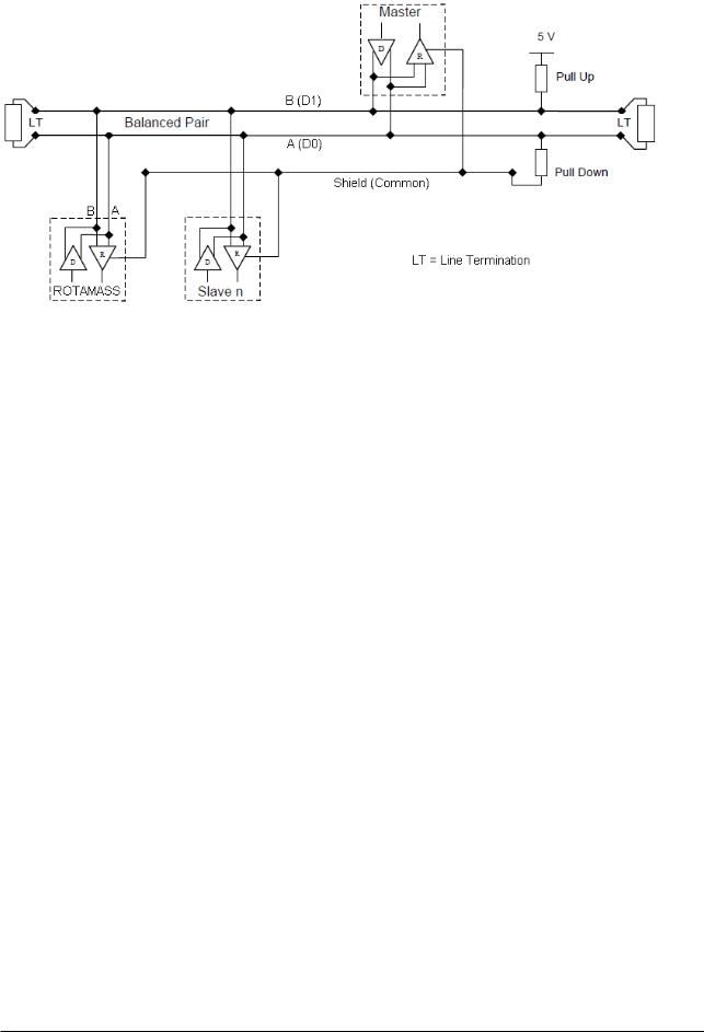
The number of devices that can be connected to a single bus without repeater is 32. The maximum cable length depends on baud rate, cable properties and network configuration. When constructing systems, both the basic and overall design must be carefully considered to allow device performance to be fully exhibited.
The following instruments are required for use with MODBUS devices:
• Terminator:
MODBUS requires two terminators at the ends of the trunk line. Refer to the supplier for details of terminators.
• Field devices:
Connect your MODBUS communication type ROTAMASS 3 Series to a MODBUS. One or more ROTAMASS 3 Series and other field devices can be connected. For the terminal assignment on the ROTAMASS 3
Series, see chapter 4.1.
• Host:
Used for accessing field devices. A dedicated host (such as DCS) is used for an instrumentation line while dedicated communication tools are used for startup or maintenance. For operation of the host, refer to the instruction manual for each host. No details of the host are explained in the rest of this manual.
• Cable:
Used for connecting devices. Refer to http://www.modbus.org/docs/Modbus_over_serial_line_V1_02.pdf for details of instrumentation cabling. If the total length of the cable is in a range of 2 to 3 meters for laboratory or other experimental use, the following simplified cable (a twisted pair wire with a cross section of 0.9 mm² or more and cycle period of within 5 cm (2 inches) may be used). Termination processing depends on the type of device being deployed. For the ROTAMASS, clamp terminal are used.
Connect the devices as shown in Figure 3.1. Connect the terminators at both ends of the trunk, with a minimum length of the spur for connection.
The polarity of signal must be maintained.
All Rights Reserved. Copyright © 2012, Rota Yokogawa |
IM 01R04B08-00E-E 1st edition February 15, 2012 -00 |
3-2 |
<3. ABOUT MODBUS>> |
Figure 3.1 Device Connection
Before using a MODBUS configuration tool other than the existing host, confirm it does not affect the loop functionality in which all devices are already installed in operation. Disconnect the relevant control loop from the bus if necessary.
IM 01R04B08-00E-E 1st edition February 15, 2012 -00 |
All Rights Reserved. Copyright © 2012, Rota Yokogawa |

<4. GETTING STARTED> |
4-1 |
4. GETTING STARTED
MODBUS is digital communication protocol and differs in operation from 4 to 20 mA transmission and the HART communication. It is recommended that users use MODBUS devices in accordance with the procedures described in this section. The procedures assume that MODBUS devices will be set up on a bench of an instrument shop.
4.1 Wiring in ROTAMASS 3 Terminal Box
Figure 4.1 I/O-Terminal Overview
Sout -
Sout +
Sin -
Sin +
Pout -
Pout +
RS485 A
RS485 B
Iout1 -
Iout1 +
Wiring:
Pulse / Status output 2 (Sout )
Status input (Sin)
Pulse / Status output 1 (Pout)
MODBUS (RS485) - MODBUS (RS485) +
Analog output 1 (Iout 1) + HART communication
F31.EPS
•Confirm one ferrite core is attached to the flowmeter.
•Insert the power cable into the ferrite core before connecting to the terminals. Fix the ferrite core to the cable with clamping wire.
•Connect the power cables to the terminals according to the figures below.
•Connect the MODBUScables to the terminals according to the figure below.
•For the connection of protective ground conductor to PE terminal of RCCF31 / RCCT3 use a crimp-on ring type terminal. For RCCR31 connect the protective ground conductor to PE terminal of terminal board.
NOTE
The maximum length of MODUS cable depends on different influences. Please see the MODBUSspecification.
All Rights Reserved. Copyright © 2012, Rota Yokogawa |
IM 01R04B08-00E-E 1st edition February 15, 2012 -00 |
4-2 |
<4. GETTING STARTED> |
4.2 Communication Setting
To activate MODBUS, the following settings are required. They are located in the MODBUS Communication menu in Detailed Setup.
IMPORTANT
Connecting the ROTAMASS MODBUS communication tool to a bus with its existing host may cause communication data scrambles resulting in a functional disorder or a system failure.
IMPORTANT
Do not turn off the power supply immediately after setting. When the parameters are saved to the EEPROM, the redundant processing is executed for the improvement of reliability. If the power is turned off within 60 seconds after setting is made, the modified parameters are not saved and the settings may return to the previous values.
Table 4.1 Communication Parameters
Function |
Parameter |
Description and Setting |
Device address |
Device address |
Select: 1 to 247 |
|
|
Set the device address for ROTAMASS where the |
|
|
host expects to communicate. Make sure that no other |
|
|
device on the bus uses the same address! |
Baud rate |
Baud rate |
Select: 1200, 2400, 4800, 9600, 19200, 38400, 57600, |
|
|
76800, 115200 |
|
|
Make sure that host and ROTAMASS use the same |
|
|
baud rate for communication |
Communication |
Data format |
Select: Even 1 stop bit, Odd 1 stop bit, None 1 stop |
settings |
|
bit, None 2 stop bits |
|
|
Make sure that host and ROTAMASS use the same |
|
|
communication settings. |
Bus mode |
Modbus mode |
Select: RTU, ASCII |
|
|
Make sure that host and ROTAMASS communicate in |
|
|
the same Modbus mode. |
|
Modbus init |
IMPORTANT |
|
|
|
|
|
The MODBUS communication module must be |
|
|
restarted after changing any of the above settings! |
|
|
This can be done by either powering off and on the |
|
|
device or by executing the function “Modbus init”. |
|
|
Please note that the settings in the menu will |
|
|
be updated after initialization of the Modbus |
|
|
communication module. |
IM 01R04B08-00E-E 1st edition February 15, 2012 -00 |
All Rights Reserved. Copyright © 2012, Rota Yokogawa |

<4. GETTING STARTED> |
4-3 |
4.3 Reading and Writing Values
Unlike other communication protocols MODBUS does not use standardized device description files but store data and parameters in registers. An overview of the Modbus registers of ROTAMASS can be found in chapter 7.
For configuration the ROTAMASS MODBUS communication tool is available from Yokogawa which can address parameters of ROTAMASS which are mapped onto MODBUS. The tool can be found on the DVD which is attached to each device. It is running under all recent PCsystem and supports all communication settings of ROTAMASS. To connect to ROTAMASS the user needs a RS232 to RS485 or USB to RS485 converter.
All Rights Reserved. Copyright © 2012, Rota Yokogawa |
IM 01R04B08-00E-E 1st edition February 15, 2012 -00 |

4-4 |
<4. GETTING STARTED> |
Blank Page
IM 01R04B08-00E-E 1st edition February 15, 2012 -00 |
All Rights Reserved. Copyright © 2012, Rota Yokogawa |

<5. OPERATION OF ROTAMASS 3 SERIES MODBUS COMMUNICATION TYPE> |
5-1 |
5. OPERATION OF ROTAMASS 3 SERIES MODBUS COMMUNICATION TYPE
5.1 Operation via display
For general information regarding the operation via display refer to the instruction manual of the standard type IM 01R04B04-00E-E. For the Modbus communication type the operation via display is basically the same. Extensions and restrictions are described below:
A menu has been added to Detailed Setup to configure the Modbus communication settings of ROTAMASS.
To establish communication please make sure to match the communication settings of your host system.
Due to memory restrictions the German language texts have been removed. Selection of German menu language is therefore not possible; all texts will remain in English.
Current output 2 is not available for Modbus communication type. All menu items referring to current output 2 have therefore been removed from the display menu.
Note: due to the ability of communicating via HART and Modbus simultaneously the operation of the display menu is slightly slower than experienced with a standard device.
5.2 Operation via HART
ROTAMASS 3 Series Modbus communication type supports also full configuration via HART communication protocol on current output 1.
For wiring and general information regarding the operation via HART communication protocol refer to the instruction manual of the standard type IM 01R04B04-00E-E.
Unless a special DD/DTM for the Modbus communication type is available the standard DD/DTM will be loaded. Therefore a few restrictions apply:
1.The Modbus communication settings menu is not available via HART but only in the display menu of ROTAMASS.
2.When changing the menu text to German, the display language will remain in English since German language texts are not available.
3.All settings for current output 2 are visible in the standard DD/DTM. However, any settings made for current output 2 will have no effect in the device since this output is not available.
5.3Operation via Modbus
All ROTAMASS 3 Series Modbus communication options support reading access to all measurement values in holding and input registers. Depending on the option configuration of selected parameters via Modbus is also supported.
For detailed information of available parameters refer to the menu tree in chapter 6.
For configuration of selection parameters for each selection a specific value has to be written.The selection values are found in the table in chapter 7.
Note:The Modbus communication settings of ROTAMASS can be changed via Modbus. However, communication continues with the previous settings.The new settings will only be taken in effect after execution of the function Modbus Init or a Power on of ROTAMASS!
Important note: Other communication protocols handle dependencies and refreshes of parameters in device description files. In the opposite Modbus accesses only single registers (values or parameters) and the host has usually no information about any other conditions. Furthermore according Modbus specification only few exception codes for certain transmission errors are defined. Therefore only physical transmission is secured by the protocol but any logical check has to be done individually by the host system. For more information refer to chapter 8.
All Rights Reserved. Copyright © 2012, Rota Yokogawa |
IM 01R04B08-00E-E 1st edition February 15, 2012 -00 |

5-2 |
<5. OPERATION OF ROTAMASS 3 SERIES MODBUS COMMUNICATION TYPE> |
|
||
|
|
Blank Page |
|
|
|
|
|
|
|
IM 01R04B08-00E-E 1st edition February 15, 2012 -00 |
All Rights Reserved. Copyright © 2012, Rota Yokogawa |

<6. PARAMETER> |
6-1 |
6. PARAMETER
Parameters in light grey are not mapped onto Modbus for ROTAMASS with option /MB1. For configuration they can still be accessed via HART communication on analog output 1 or via the display menu. Parameters in dark grey are not available. The default value of selection items is typed in bold letters.
Language |
English |
|
|
|
|
|
German |
|
|
|
|
|
French |
|
|
|
|
|
|
|
|
|
|
|
Russian |
|
|
|
|
|
|
|
|
|
|
|
|
|
|
|
|
Process |
View fld dev vars |
Mass flow |
|
|
R |
|
|
|
|
|
|
Variables |
|
Volume flow |
|
|
R |
|
|
Density |
|
|
R |
|
|
|
|
|
|
|
|
Temperature |
|
|
R |
|
|
Concentration meas |
|
|
R |
|
|
|
|
|
|
|
|
Net flow |
|
|
R |
|
|
F-Total flex |
|
|
R |
|
|
|
|
|
|
|
|
R-Total flex |
|
|
R |
|
|
D-Total flex |
|
|
R |
|
|
|
|
|
|
|
|
F-Total mass |
|
|
R |
|
|
|
|
|
|
|
|
R-Total mass |
|
|
R |
|
|
|
|
|
|
|
|
D-Total mass |
|
|
R |
|
|
F-Total volume |
|
|
R |
|
|
|
|
|
|
|
|
R-Total volume |
|
|
R |
|
|
D-Total volume |
|
|
R |
|
|
|
|
|
|
|
|
F-Total net |
|
|
R |
|
|
R-Total net |
|
|
R |
|
|
|
|
|
|
|
|
D-Total net |
|
|
R |
|
|
F-Total energy |
|
|
R |
|
|
|
|
|
|
|
|
Velocity |
|
|
R |
|
|
Drive gain |
|
|
R |
|
|
|
|
|
|
|
View outputs |
Analog output 1 |
Analog Output 1 |
|
R |
|
|
|
|
|
|
|
|
|
Analog Output 1% |
|
R |
|
|
|
|
|
|
|
|
|
Analog Output 1mA |
|
R |
|
|
|
|
|
|
|
|
|
|
|
|
|
|
Pulse/Status out 1 |
Pulse output 1 |
|
R |
|
|
|
Status output 1 |
|
R |
|
|
|
|
|
|
|
|
Pulse/Status out 2 |
Pulse output 2 |
|
R |
|
|
|
|
|
|
|
|
|
Status output 2 |
|
R |
|
|
|
|
|
|
|
View input |
|
|
|
R |
|
|
|
|
|
|
|
Totalizer |
Total reset cntrl |
Inhibit |
|
Sel |
|
|
|
Enable |
|
|
|
|
|
|
|
|
|
|
|
|
|
|
|
|
|
Total reset |
Not Execute |
|
|
|
|
|
|
|
|
|
|
|
Reset flex totals |
EXE |
|
|
|
|
Reset mass totals |
EXE |
|
|
|
|
|
|
|
|
|
|
Reset volume totals |
EXE |
|
|
|
|
|
|
|
|
|
|
Reset net totals |
EXE |
|
|
|
|
Reset all totals |
EXE |
|
|
|
|
|
|
All Rights Reserved. Copyright © 2012, Rota Yokogawa |
IM 01R04B08-00E-E 1st edition February 15, 2012 -00 |

6-2 |
<6. PARAMETER> |
|
|
|
|
|
|
|
|
Diag/Service |
Self test/Status |
Self Test |
LCD Test |
EXE |
|
|
|
|
|
|
|
|
Self Test |
EXE |
|
|
|
|
|
|
|
|
Key Test |
EXE |
|
|
|
|
|
|
|
|
|
|
|
|
Status |
Event Overview |
R |
|
|
|
Error |
R |
|
|
|
|
|
|
|
|
Alarm |
R |
|
|
|
|
|
|
|
|
Warning |
R |
|
|
|
|
|
|
|
Hist Overfiew ord |
Hist Overview ord |
R |
|
|
|
Clear History |
EXE |
|
|
|
|
|
|
|
Hist Overfiew abs |
Hist Overview abs |
R |
|
|
|
|
|
|
|
|
Error |
R |
|
|
|
Alarm |
R |
|
|
|
|
|
|
|
|
Warning |
R |
|
|
|
Clear History |
EXE |
|
|
|
|
|
|
|
|
|
|
|
|
Error History |
|
R |
|
|
|
|
|
|
Input/Output test |
Analog output 1 |
|
R/W |
|
|
|
|
|
|
|
Pulse output 1 |
|
R/W |
|
|
|
|
|
|
|
Status output 1 |
|
R/W |
|
|
Pulse output 2 |
|
R/W |
|
|
|
|
|
|
|
Status output 2 |
|
R/W |
|
|
Status input |
|
R |
|
|
|
|
|
|
|
|
|
|
|
Auto zero check |
Autozero history |
|
R |
|
|
|
|
|
|
|
|
|
|
|
|
Autozero initial |
|
R |
|
|
|
|
|
|
|
Autozero range |
|
R |
|
|
|
|
|
|
|
Autozero fluctuation |
|
R |
|
|
range |
|
|
|
|
|
|
|
|
|
|
|
|
|
Autozero |
Zero tuning |
Inhibit |
Sel |
|
|
|
Enable |
|
|
|
|
|
|
|
|
|
|
|
|
|
Autozero time |
3min |
Sel |
|
|
|
|
|
|
|
|
30s |
|
|
|
|
|
|
|
|
Autozero Exe |
|
EXE |
|
|
|
|
|
|
|
Autozero value |
|
R |
|
|
|
|
|
|
Output trim |
AO 1 trim 4mA |
|
EXE |
|
|
|
|
|
|
|
|
|
|
|
|
AO 1 trim 20mA |
|
EXE |
|
|
|
|
|
IM 01R04B08-00E-E 1st edition February 15, 2012 -00 |
All Rights Reserved. Copyright © 2012, Rota Yokogawa |

|
|
|
<6. PARAMETER> |
6-3 |
|
|
|
|
|
|
|
Basic Setup |
Tag |
|
|
|
R/W |
|
|
|
|
|
|
|
Long Tag |
|
|
|
R/W |
|
|
|
|
|
|
|
Display config |
Disp select 1 |
Mass flow |
|
Sel |
|
|
|
Volume flow |
|
|
|
|
|
|
|
|
|
|
|
Density |
|
|
|
|
|
Temperature |
|
|
|
|
|
|
|
|
|
|
|
Concentration meas |
|
|
|
|
|
Net flow |
|
|
|
|
|
|
|
|
|
|
|
F-Total flex |
|
|
|
|
|
R-Total flex |
|
|
|
|
|
|
|
|
|
|
|
D-Total flex |
|
|
|
|
|
F-Total mass |
|
|
|
|
|
|
|
|
|
|
|
R-Total mass |
|
|
|
|
|
D-Total mass |
|
|
|
|
|
|
|
|
|
|
|
F-Total volume |
|
|
|
|
|
|
|
|
|
|
|
R-Total volume |
|
|
|
|
|
|
|
|
|
|
|
D-Total volume |
|
|
|
|
|
|
|
|
|
|
|
F-Total net |
|
|
|
|
|
R-Total net |
|
|
|
|
|
|
|
|
|
|
|
D-Total net |
|
|
|
|
|
F-Total energy |
|
|
|
|
|
|
|
|
|
|
|
Velocity |
|
|
|
|
|
Drive gain |
|
|
|
|
|
|
|
|
|
|
|
|
|
|
|
|
Disp select 2 |
Mass flow |
|
Sel |
|
|
|
|
|
|
|
|
|
Volume flow |
|
|
|
|
|
Density |
|
|
|
|
|
|
|
|
|
|
|
Temperature |
|
|
|
|
|
Concentration meas |
|
|
|
|
|
|
|
|
|
|
|
Net flow |
|
|
|
|
|
|
|
|
|
|
|
F-Total flex |
|
|
|
|
|
|
|
|
|
|
|
R-Total flex |
|
|
|
|
|
D-Total flex |
|
|
|
|
|
F-Total mass |
|
|
|
|
|
|
|
|
|
|
|
R-Total mass |
|
|
|
|
|
D-Total mass |
|
|
|
|
|
|
|
|
|
|
|
F-Total volume |
|
|
|
|
|
R-Total volume |
|
|
|
|
|
|
|
|
|
|
|
D-Total volume |
|
|
|
|
|
F-Total net |
|
|
|
|
|
|
|
|
|
|
|
R-Total net |
|
|
|
|
|
D-Total net |
|
|
|
|
|
|
|
|
|
|
|
F-Total energy |
|
|
|
|
|
Velocity |
|
|
|
|
|
|
|
|
|
|
|
Drive gain |
|
|
|
|
|
None |
|
|
|
|
|
|
|
|
|
|
|
|
|
|
All Rights Reserved. Copyright © 2012, Rota Yokogawa |
IM 01R04B08-00E-E 1st edition February 15, 2012 -00 |
 Loading...