


User’s
Manual
DPharp
Differential Pressure and
Pressure Transmitters
Manual Change No. 13-004
Please refer to this manual change for the handling cautions ofATEX certification if the products include the option code /KS2 or /KF21.
IM No. |
Model & Option code |
IM 01C25A01-01E
IM 01C25B01-01E
IM 01C25C01-01E
IM 01C25F01-01E
EJXAwith option code /KS2 or /KF21
IM 01C25H01-01E
IM 01C25K01-01E
June 28, 2013
ATEX Certification
(1) Technical Data
a. ATEX Intrinsically Safe Type
Caution forATEX Intrinsically safe type.
Note 1. Model EJX Series pressure transmitters with optional code /KS2 for potentially explosive atmospheres:
•No. KEMA03ATEX1544 X
•Applicable Standard:
EN 50014:1997, EN 50020:2002, EN 50284:1999, EN 50281-1-1:1998
•Type of Protection and Marking code: EEx ia IIC T4
•Group: II
•Category: 1G, 1D
•Ambient Temperature for gas-proof: –50 to 60°C
•Process Temperature (Tp.): 120°C max.
•Maximum Surface Temperature for dustproof:
T85°C (Tamb.: –40* to 60°C, Tp.: 80°C) T100°C (Tamb.: –40* to 60°C, Tp.: 100°C)
T120°C (Tamb.: –40* to 60°C, Tp.: 120°C)
* –15°C when /HE is specified.
•Enclosure: IP66 and IP67
Note 2. Electrical Data
•In type of explosion protection intrinsic safety EEx ia IIC only for connection to a certified intrinsically safe circuit with following maximum values:
Ui = 30 V Ii = 200 mA Pi = 0.9 W
Effective internal capacitance; Ci = 10 nF Effective internal inductance; Li = 0 mH
Note 3. Installation
•All wiring shall comply with local installation requirements. (Refer to the installation diagram)
Note 4. Maintenance and Repair
•The instrument modification or parts replacement by other than authorized representative of Yokogawa Electric Corporation is prohibited and will void DEKRA(KEMA) Intrinsically safe Certification.
Note 5. Special Conditions for Safe Use
•In the case where the enclosure of the Pressure Transmitter is made of aluminium,
if it is mounted in an area where the use of category 1 G apparatus is required, it must be installed such, that, even in the event of rare incidents, ignition sources due to impact and friction sparks are excluded.
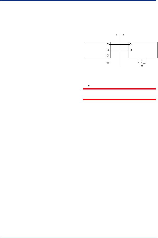
[Installation Diagram]
Hazardous Location |
Nonhazardous Location |
Transmitter |
|
+ |
+ |
Supply |
Safety Barrier *1 |
– |
– |
F0206r.ai
*1: In any safety barriers used the output current must be limited by a resistor “R” such that Imaxout-Uz/R.
 WARNING
To satisfy IP66 or IP67, apply waterproof glands to the electrical connection port.
b. ATEX Flameproof Type
Caution forATEX flameproof type.
Note 1. Model EJX Series pressure transmitters with optional code /KF21 for potentially explosive atmospheres:
•No. KEMA07ATEX0109
•Applicable Standard: EN 60079-0:2006, EN 60079-1:2004, EN 61241-0:2006, EN 61241-1:2004
•Type of Protection and Marking Code: Ex d IIC T6...T4, Ex tDA21 IP6x T85, T100, T120
•Group: II
•Category: 2G, 2D
•Enclosure: IP66 and IP67
•Temperature Class for gas-poof: T6, T5, and T4
•Ambient Temperature for gas-proof: –50 to 75°C (T6), –50 to 80°C (T5), and –50 to 75°C (T4)
•Maximum Process Temperature (Tp.) for gas-proof:
85°C (T6), 100°C (T5), and 120°C (T4)
•Maximum Surface Temperature for dustproof:
T85°C (Tamb.: –40* to 40°C, Tp.: 80°C) T100°C (Tamb.: –40* to 60°C, Tp.: 100°C) T120°C (Tamb.: –40* to 80°C, Tp.: 120°C)
* –15°C when /HE is specified.
 Loading...