


IDENTIFICATION NUMBERS RECORD
Record the frame serial number and engine serial number in the spaces provided for assistance when ordering spare parts from a Yamaha dealer or reference in case the vehicle is stolen.
1. FRAME SERIAL NUMBER: |
2. ENGINE SERIAL NUMBER: |
|
|
|
|
|
|
|
II

XTZ 125K / XTZ 125E
OWNER’S MANUAL
© 2003 Yamaha Motor da Amazônia Ltda. 1st edition, April 2003
All rights reserved.
Any reprinting or unauthorized use without the written permission of
Yamaha Motor da Amazônia Ltda. is expressly prohibited.
Printed in Brazil.
III
INTRODUCTION
Congratulations on your purchase of the YAMAHA XTZ 125K / XTZ 125E. This model is the result of Yamaha’s vast experience in the production of fine sporting, touring, and pacesetting racing machines. It represents the high degree of craftmanship and reliability that have made Yamaha a leader in these fields.
This manual will give you an understanding of the operation, inspection, and basic maintenance of this motorcycle.
If you have any questions about the operation or maintenance of your motorcycle, please consult a Yamaha dealer.
YAMAHA MOTOR DA AMAZÕNIA LTDA.
IV

Particularly important information is distinguished in this manual by the following notations:
NOTE: |
A NOTE provides key information to make procedures easier or clearer. |
|
|
CAUTION: |
A CAUTION indicates special precautions that must be taken to avoid damage to the machine. |
|
|
WARNING: |
Failure to follow WARNING instructions could result in severe injury or death to the machine operator, |
|
a bystander or a person inspecting or repairing the machine. |
NOTE:
This manual should be considered a permanent part of this machine and should remain with it even if the machine is subsequently sold.
Yamaha continually seeks advancements in product design and quality. Therefore, while this manual contains the most current product information available at the time of printing. There may be minor discrepancies between your machine and this manual.
If there is any question concerning this manual, please consult your Yamaha dealer.
V

WARNING:
PLEASE READ THIS MANUAL CAREFULLY AND COMPLETELY BEFORE OPERATING THIS MACHINE. DO NOT
ATTEMPT TO OPERATE THIS MOTORCYCLE UNTIL YOU HAVE ATTAINED A SATISFACTORY KNOWLEDGE OF ITS CONTROLS AND OPERATING FEATURES AND UNTIL YOU HAVE BEEN TRAINED IN SAFE AND PROPER RIDING TECHNIQUES. REGULAR INSPECTIONS AND CAREFUL MAINTENANCE, ALONG WITH GOOD RIDING SKILLS WILL ENSURE THAT YOU SAFELY ENJOY THE CAPABILITIES AND THE RELIABILITY OF THIS MOTORCYCLE.
VI
SAFETY INFORMATION
TWO-WHEELED Machines ARE SINGLE TRACK VEHICLES. THEIR SAFE USE AND OPERATION ARE DEPENDENT
UPON THE USE OF PROPER RIDING TECHNIQUES AS WELL AS THE EXPERTISE OF THE OPERATOR.
EVERY OPERATOR SHOULD KNOW THE FOLLOWING REQUIREMENTS BEFORE RIDING. HE OR SHE SHOULD.
1.OBTAIN THOROUGH INSTRUCTIONS FORM A COMPETENT SOURCE ON ALL ASPECTS OF MACHINE
OPERATION.
2.OBSERVE THE WARNINGS AND MAINTENANCE REQUIREMENTS IN THE OWNER’S MANUAL.
3.OBTAIN QUALIFIED TRAINING IN SAFE AND PROPER RIDING TECHNIQUES.
4.OBTAIN PROFESSIONAL TECHNICAL SERVICE AS INDICATED BY THE OWNER’S MANUAL AND/OR WHEN
MADE NECESSARY BY MECHANICAL CONDITIONS.
SAFE RIDING
1.Always make pre-operation checks. Careful checks may help prevent an accident.
2.Many accidents involve inexperienced operators.
a.Know your skills and limits. Staying within your limits may help you to avoid an accident.
b.Only lend your machine to experienced operators.
3.Many machine accidents have been caused by machine operator errors. A typical error made by the operator is veering wide on a turn due to EXCESSIVE SPEED or undercornering (insufficient lean angle for the speed). Never travel faster than warranted by conditions.
4.Ride cautiously in unfamiliar areas. You may encounter hidden obstacles which could cause an accident.
5.The operator’s posture is important for proper control. The operator should keep both hands on the handlebars and both feet on the operator footrests during operation to maintain control of the machine.
6.Never ride under the influence of alcohol or drugs.
VII
PROTECTIVE APPAREL
The majority of fatalities from machine accidents are the result of head injuries. The use of a safety helmet is the single
most critical factor in the prevention or reduction of head injuries.
1.Always wear an approved helmet.
2.Wear a face shield or goggles. Wind on your unprotected eyes could contribute to an impairment of vision which
could delay seeing a hazard.
3.The use of heavy boots, jacket, trousers, gloves, etc. is effective in preventing or reducing abrasions or lacerations.
4.Never wear loose fitting clothing. It could catch on the control levers, footrests, or wheels and cause injury or accident.
5.Never touch the engine or exhaust system during or after operation. They become very hot and can cause burns. Always wear protective clothing that covers your legs, ankles and feet.
6.Always use clear clothes to make your visualization easier.
7.Items above must also be followed by pillion rider.
MODIFICATION
Modifications made to the machine not approved by Yamaha, or the removal of original equipment, may render your machine unsafe for use and may cause severe personal injury. Modifications may also make your machine illegal to use.
VIII

ACCESSORIES AND LOADING
Adding accessories or cargo to your machine can adversely affect stability and handling if the weight distribution of the machine is changed. To avoid the possibility of an accident, extreme caution should be used if adding cargo or accessories to your machine.
Use extra care if riding a machine which has added cargo or acessories. Genuine Yamaha accessories have been specifically designed for use on this machine. Since Yamaha cannot test all other accessories which may be available, you must personally be responsible for the proper selection, installation and use of non-Yamaha accessories.
You should use extreme caution when selecting and installing any accessories. Keep in mind these guidelines for mounting accessories in addition to those provided under “LOADING”.
1.Never install accessories or carry cargo that would impair the performance of your machine. Carefully inspect the accessory before using it to make sure it does not in any way reduce ground clearance or cornering clearance, limit suspension travel, steering travel or control operation, or obscure lights or reflectors.
a.Accessories fitted to the handlebar or the front fork area can create instability due to improper weight distribution or aerodynamic changes. If accessories are added to the handlebar or front fork area, they must be as lightweight as possible and should be kept to a minimum.
b.Bulky or large accessories may seriously affect the stability of the machine due to aerodynamic effects. Wind may attempt to lift the machine, or the machine may become unstable in cross winds. These accessories may also cause instability when being passed by or passing large vehicles.
c.Certain accessories can displace the operator from his or her normal riding position. This improper position limits the freedom of movement of the operator and may limit control ability. Therefore such accessories are not recommended.
2.Caution must be used if adding electrical accessories. If these accessories exceed the capacity of the machine’s electrical system, an electric failure could result, which could cause a dangerous loss of lights or engine power.
IX
GASOLINE AND EXHAUST GAS
1.GASOLINE IS HIGHLY FLAMMABLE:
a.Always turn off the engine when refueling.
b.Take care not to spill any gasoline on the engine or exhaust system when refueling.
c.Never refuel while smoking or in the vicinity of an open flame.
2.Never start the engine or let it run for any length of time in a closed area. The exhaust fumes are poisonous and may cause loss of consciousness and death within a short time. Always operate your motorcycle in an area that has adequate ventilation.
3.Always turn off the engine before leaving the machine unattended and remove the ignition key. When parking the machine, note the following:
a.The engine and exhaust system may be hot. Park the machine in a place where pedestrians or children are not likely to touch these hot areas.
b.Do not park the machine on a slope or soft ground; the machine may fall over.
c.Do not park the machine near a flammable source, e. g. a kerosene heater, or near an open flame. The machine could catch fire.
4.When transporting the machine in another vehicle, be sure it is kept upright and that the fuel cock is turned to “ON” or “RES” (for vacuum type) / “OFF” (for manual type).
If it should lean over, gasoline may leak out of the carburetor or fuel tank.
5.If you should swallow any gasoline, inhale a lot of gasoline vapor, or allow gasoline to get in your eyes, see your doctor immediately. If any gasoline spills on your skin or clothing, immediately wash it off with soap and water and change your clothes.
X
ÍNDICE
DESCRIPTION XTZ 125K ................................... |
1-1 |
DESCRIPTION XTZ 125E ................................... |
1-2 |
MACHINE IDENTIFICATION ................................ |
2-1 |
Vehicle identification number .................... |
2-1 |
Engine serial number ................................ |
2-1 |
CONTROL FUNCTIONS ...................................... |
3-1 |
Main switch ............................................... |
3-1 |
Indicator lights ........................................... |
3-2 |
Speedometer ............................................ |
3-3 |
Handlebar switches over left .................... |
3-4 |
Handlebar switches over right .................. |
3-5 |
Clutch lever ............................................... |
3-6 |
Shift pedal ................................................. |
3-6 |
Front brake lever ....................................... |
3-7 |
Rear brake pedal ...................................... |
3-7 |
Fuel tank cap ............................................ |
3-8 |
Fuel cock .................................................. |
3-9 |
Starter lever .............................................. |
3-10 |
Kick Starter ............................................... |
3-10 |
Steering lock ............................................. |
3-11 |
Seat ........................................................... |
3-12 |
Side covers ............................................... |
3-13 |
Rear shock absorber ................................ |
3-14 |
Clutch switch operation check .................. |
3-15 |
PRE-OPERATION CHECKS ................................ |
4-1 |
Brakes ....................................................... |
4-3 |
Brake fluid leakage ................................... |
4-4 |
Engine oil .................................................. |
4-4 |
Tires .......................................................... |
4-5 |
Clutch ........................................................ |
4-8 |
Throttle grip ............................................... |
4-8 |
Fitting/Fasteners ....................................... |
4-8 |
Switches .................................................... |
4-8 |
Wheels ...................................................... |
4-8 |
Fuel ........................................................... |
4-9 |
OPERATION AND IMPORTANT RIDING |
|
POINTS ................................................................. |
5-1 |
Starting a cold engine ............................... |
5-2 |
Starting a warm engine ............................. |
5-5 |
Warming up the engine ............................. |
5-5 |
Shifting ...................................................... |
5-6 |
Tips for reducing fuel consumption ........... |
5-7 |
Engine Break-in ........................................ |
5-7 |
Parking ...................................................... |
5-8 |
PERIODIC MAINTENANCE AND MINOR |
|
REPAIRS .............................................................. |
6-1 |
XI

Tool kit ...................................................... |
6-2 |
PERIODIC MAINTENANCE/LUBRICATION ........ |
6-3 |
Torque specifications ................................ |
6-5 |
Engine oil .................................................. |
6-6 |
Oil pressure .............................................. |
6-9 |
Air filter ...................................................... |
6-10 |
Carburetor adjustment .............................. |
6-12 |
Valve clearance adjustment ...................... |
6-12 |
Idle speed adjustment ............................... |
6-13 |
Throttle cable adjustment ......................... |
6-14 |
Spark plug inspection ............................... |
6-15 |
Clutch adjustment ..................................... |
6-16 |
Front brake adjustment ............................. |
6-17 |
Rear brake adjustment ............................. |
6-18 |
Brake light switch adjustment ................... |
6-20 |
Checking the front brake pads and rear brake |
|
shoes ........................................................ |
6-20 |
Front brake ............................................... |
6-21 |
Rear brake ................................................ |
6-21 |
Inspecting the brake fluid level ................. |
6-22 |
Brake fluid replacement ............................ |
6-23 |
Drive chain slack check ............................ |
6-24 |
Drive chain slack adjustment .................... |
6-25 |
Drive chain lubrication .............................. |
6-26 |
Cable inspection and lubrication ............... |
6-26 |
Throttle cable and grip lubrication ............ |
6-27 |
Brake and shift pedals .............................. |
6-27 |
Brake and clutch levers ............................ |
6-27 |
Rear suspension ....................................... |
6-28 |
Sidestand .................................................. |
6-28 |
Front fork inspection ................................. |
6-29 |
Rear shock absorber adjustment .............. |
6-30 |
Steering inspection ................................... |
6-31 |
Wheel bearings ......................................... |
6-31 |
Battery ...................................................... |
6-32 |
Replenishing the battery fluid ................... |
6-33 |
Storage the battery ................................... |
6-34 |
Fuse replacement ..................................... |
6-34 |
Headlight bulb replacement ...................... |
6-35 |
Front wheel removal ................................. |
6-37 |
Front wheel installation ............................. |
6-38 |
Rear wheel removal .................................. |
6-39 |
Rear wheel installation .............................. |
6-40 |
Troubleshooting ........................................ |
6-41 |
Troubleshooting chart ............................... |
6-42 |
CLEANING AND STORAGE ................................ |
7-1 |
Cleaning .................................................... |
7-1 |
Storage ..................................................... |
7-2 |
SPECIFICATIONS ................................................ |
8-1 |
XII

DESCRIPTION XTZ 125K
01. |
Fuel cock |
10. |
Dispstick |
02. |
Starter lever |
11. |
Rear brake pedal |
03. |
Battery |
12. |
Clutch lever |
04. |
Fusible |
13. |
Handlebar switches over right |
05. |
Tool kit |
14. |
Speedometer |
06. |
Shift pedal |
15. |
Main switch |
07. |
Shock absorber |
16. |
Front brake lever |
08. |
Air filter |
17. |
Throttle grip |
09. |
Kick starter |
18. |
Handlebar switches over left |
|
|
19. |
Fuel tank cap |
1-1
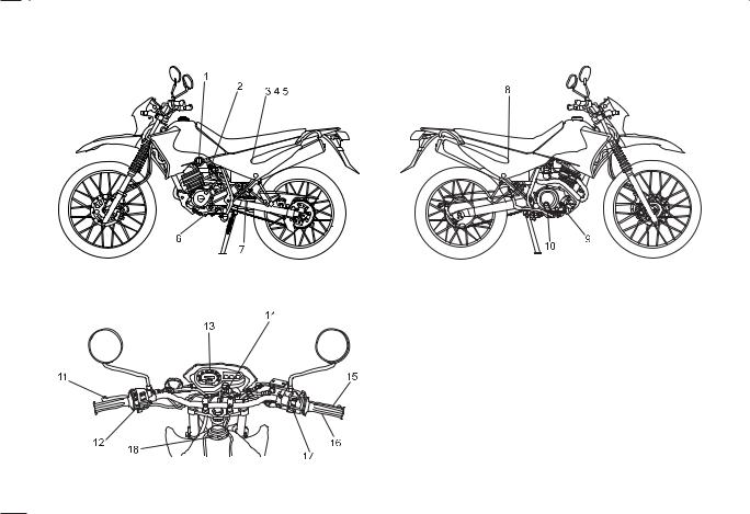
DESCRIPTION XTZ 125E
01. |
Fuel cock |
10. |
Rear brake pedal |
02. |
Starter lever |
11. |
Clutch lever |
03. |
Battery |
12. |
Handlebar switches over right |
04. |
Fusible |
13. |
Speedometer |
05. |
Tool kit |
14. |
Main switch |
06. |
Shift pedal |
15. |
Front brake lever |
07. |
Shock absorber |
16. |
Throttle grip |
08. |
Air filter |
17. |
Handlebar switches over left |
09. |
Dispstick |
18. |
Fuel tank cap |
1-2
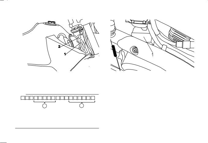
MACHINE IDENTIFICATION
Vehicle identification number |
Engine serial number |
|
|
|
|
1. Frame number |
2. Production year |
The vehicle identification number is stamped into the steering head pipe.Record this number in the space provided.
NOTE:
1. Engine serial number
The engine serial number is stamped on right-hand engine
crankcase.
A B
Model code is indicated by 4th to 8th ) digits and serial number is indicated by 12th to 17th digits *. Record these numbers for reference in case of ordering parts from a Yamaha dealer.
2-1
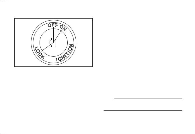
CONTROL FUNCTIONS
Main switch
The main switch controls the ignition and the electrical system. It’s operation is described below.
ON:
Electrical circuits are switched on. Engine can be started.
The key cannot be removed.
OFF:
All electrical circuits are switched off. The key can be removed.
LOCK:
The steering is locked and all electrical circuits are switched off. The key can be removed. Refer to page (3-11) “Steering lock” for instructions.
NOTE:
Always turn the main switch to “OFF” or “LOCK” and remove the key when the motorcycle is unattended.
3-1
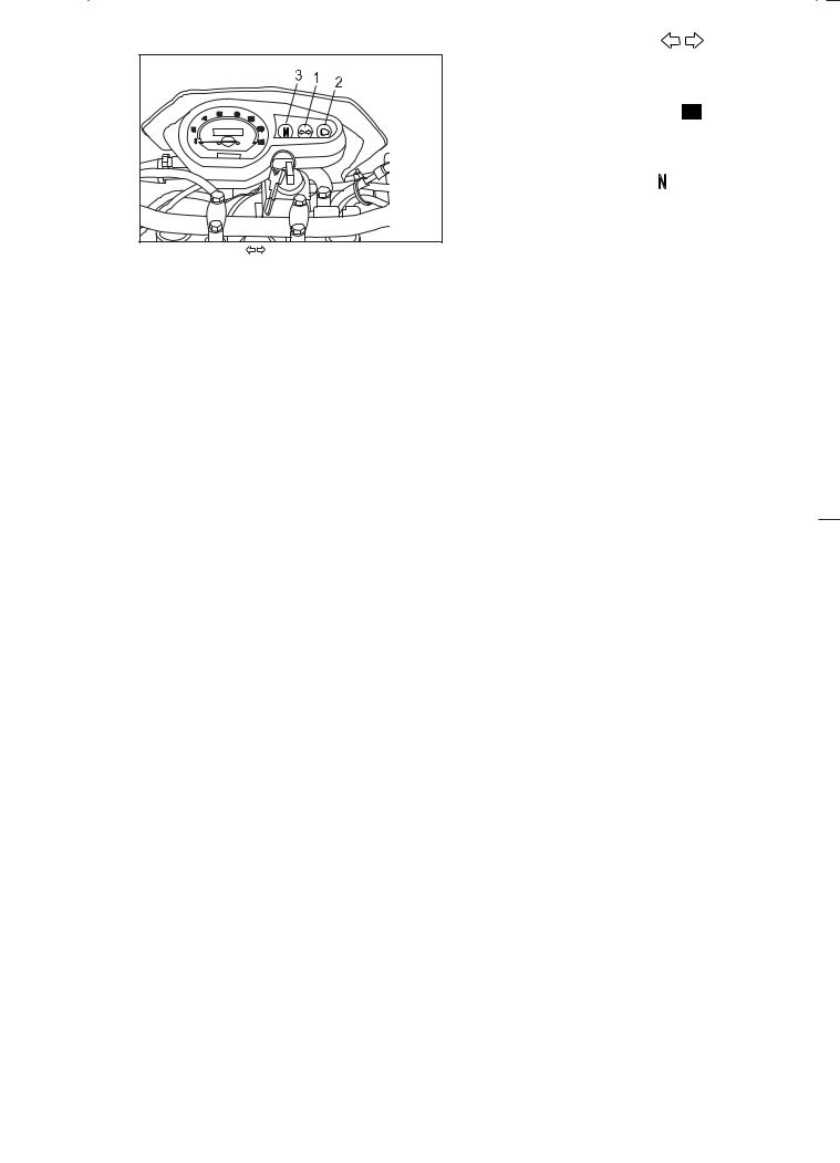
Indicator lights |
TURN INDICATOR LIGHTS " |
" |
|
The corresponding indicator fhashes when the turn switch |
|
|
is moved to the “ç “ or è““. |
|
|
HIGH BEAM INDICATOR LIGHT " |
" |
|
This indicator comes on when the headlight high beam is |
|
|
used. |
|
|
NEUTRAL INDICATOR LIGHT " " |
|
|
This indicator comes on when the transmission is in neutral. |
|
1. Turn indicator lights " |
" |
|
2.High beam indicator light " "
"
3.Neutral indicator light "N"
3-2
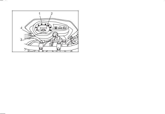
Speedometer |
1. Speedometer |
2. Odometer |
3. Trip meter |
4. Adjusting knob |
The speedometer shows riding speed.
This speedometer is equipped with an odometer and a trip meter.
The trip meter can be returned to zero by using the adjusting knob.
Use the trip meter to estimate how for you can ride on a tank of fuel.
This information will enable you to plan fuel stops in the future.
3-3
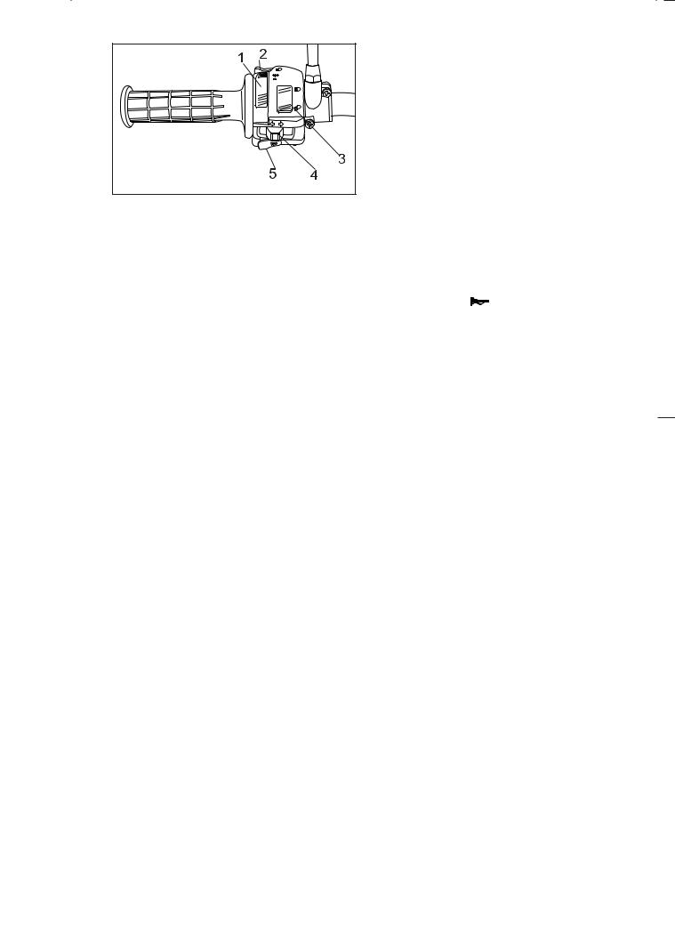
Handlebar switches over left:
1.Light switch
2.Pass switch
3.Dimmer switch
4.Turn signal switch
5.Horn switch
LIGHTS SWITCH |
|
|
|
|
|
|
Turning the light switch to |
|
“, turns on the meter lights |
||||
|
||||||
and tail-lights. Turning the light switch to |
|
“, turns the |
||||
|
||||||
headlight on also. |
|
|
|
|
|
|
|
|
|
|
|
|
|
PASS SWITCH " |
|
|
|
|
|
|
|
" |
|
|
|
|
|
Press the switch to operate the passing light.
DIMMER SWITCH
Turn the switch to "  " for the high beam and to "
 " for the low beam.
TURN SIGNAL SWITCH " |
|
" |
|
|
|
|
To signal a right-hand turn, push the switch to “ |
|
“ ; to |
||||
|
|
|
|
|
|
|
signal a left-hand turn, push the switch to |
|
|
“ . |
|||
|
|
|
|
|
|
|
Once the switch is released it will return to the center position. To cancel the signal, push the switch in after it has returned to the center position.
HORN SWITCH " |
" |
Press the switch to sound the horn.
3-4
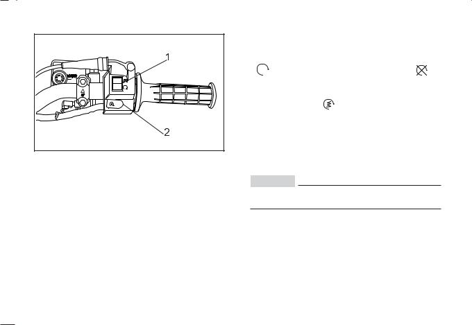
Handlebar switches over right: |
“ENGINE STOP” SWITCH |
|
||
|
The engine stop switch is a safety device for use in an |
|||
|
emergency such as when the motorcycle overturns or if |
|||
|
trouble occurs in the throttle system. Turn the switch to |
|||
|
“ |
” to start the engine, and turn the switch to “ |
” to |
|
|
stop the engine. |
|
|
|
|
STARTER SWITCH “ |
” |
|
|
|
The starter motor cranks the engine when pushing the |
|||
|
starter switch. |
|
|
|
1. “ENGINE STOP” switch, shuts the engine off |
|
|
|
|
2. Starter switch (XTZ 125E) |
|
|
|
|
|
CAUTION: |
|
|
|
See starting instructions prior to starting the
engine.
3-5
Clutch lever
1. Clutch lever
Shift pedal
1. Shift pedal
The clutch lever is located on the left handlebar, and the starting circuit cut off switch is incorporated in the clutch lever holder. Pull the clutch lever to the handlebar to disengage the clutch, and release the lever to engage the clutch. The lever should be pulled rapidly and released slowly for smooth clutch operation.
This motorcycle is equipped with a constant-mesh 5-speed transmission.
The shift pedal is located on the left side of the engine and is used in combination with the clutch when shifting.
3-6
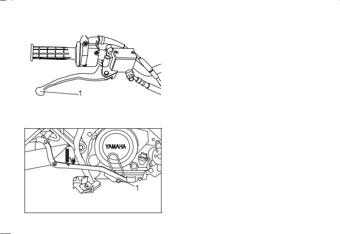
Front brake lever |
The front brake lever is located on the right handlebar. Pull |
|
it toward the handlebar to apply the front brake. |
|
|
|
|
1. Front brake lever
Rear brake pedal
The rear brake pedal is on the right side of the motorcycle. Press down the brake pedal to apply the rear brake.
1.Rear brake pedal
3-7
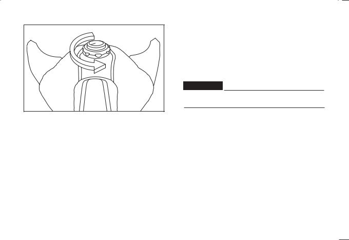
Fuel tank cap |
TO OPEN: |
|
Insert the key and turn it 1/2 turn counterclockwise. The |
|
lock will be released and the cap can be opened. |
|
TO CLOSE: |
|
Push the tank cap into position with the key inserted. To |
|
remove the key, turn it clockwise to the original position. |
WARNING:
Be sure the cap is properly installed and locked in place before riding the motorcycle.
3-8
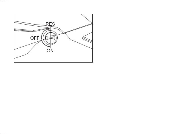
Fuel cock |
The fuel cock supplies fuel from the tank to the carburetor |
|
while filtering it also. |
|
|
|
The fuel cock has three positions: |
OFF:
With the fuel cock in this position, fuel will not flow. Always set the fuel cock to this position when the engine is not running.
ON:
With the fuel cock in this position, fuel flows to the carburetor. Set the fuel cock to this position when starting the engine and while riding.
RES:
This indicates reserve. If you run out of fuel while riding, set the fuel cock to this position.
Fill the tank at the first opportunity. Be sure to set fuel cock back to “ON” after refueling!
3-9
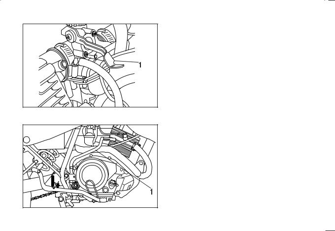
Starter lever
1. Starter lever
Kick starter
1. Kick starter (XTZ 125K)
Starting a cold engine requires a richer air-fuel mixture. A separate starter circuit supplies the mixture.
Pull the starter knob up to open the circuit for starting. When the engine has warmed up, push the knob down to close the circuit.
Rotate the kick starter away from the engine. Push the starter down lighty with your foot until the gears engage, then kick smoothly and forcefully to start the engine.
Shift to neutral before starting.
3-10

Steering lock
The steering is locked when the main switch is turned to “LOCK”. To lock the steering, turn the handlebars all the way to the left. With the key at “OFF” position, push it into the main switch and release it, turn it counterclockwise to “LOCK”, and remove the key. To release the lock, turn the key to “OFF”.
WARNING:
Never turn the key to “LOCK” position when the
motorcycle is moving.
1. Push |
2. Release |
3. Turn |
3-11
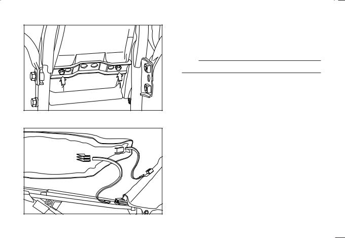
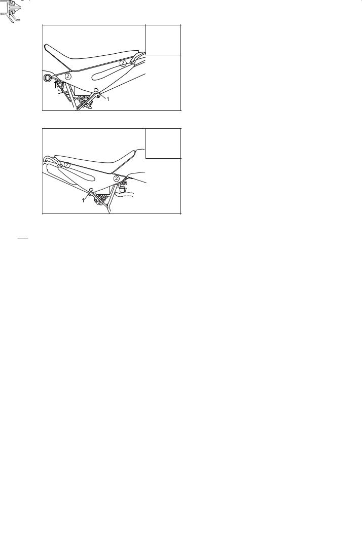
Seat |
1. Bolts
To remove the seat, remove the bolts.
To reinstall the seat, insert the lobes in to the receptacle on the frame and fuel tank, then tighten the bolts.
Reinstall the side covers.
NOTE:
Make sure the seat is securely fitted.
3-12
Side covers
|
|
|
A |
1. Lock the side cover |
2. |
Pull |
A. Pin |
Insert the key and turn it 1/4 clockwise. Pull the cover to release the pins.
To reinstall, reverse the removal procedures.
|
|
|
A |
1. Screw |
2. |
Pull |
3. Pin |
Remove the screw and then pull the cover to release the pins
To reinstall, reverse the removal procedures.
3-13
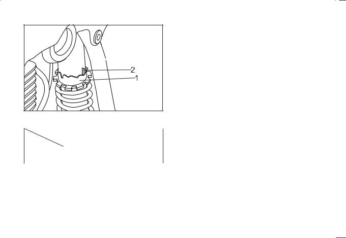
Rear shock absorber |
The spring prelod can be adjusted to suit the motorcycle’s |
|
load (ex: optional accessories, etc.) and riding conditions. |
|
Refer to page 6-30 for proper adjustment procedures. |
1. Spring preload adjusting ring 2.Position indicator
|
Soft |
|
Standard |
|
|
Hard |
|
||
|
|
|
|
|
|
|
|
|
|
Adjusting |
1 |
|
2 |
3 |
4 |
5 |
|
6 |
7 |
position |
|
|
|||||||
|
|
|
|
|
|
|
|
|
|
|
|
|
|
|
|
|
|
|
|
3-14
* Clutch switch operation check
Check the operation of the clutch switch against the
information below.
TURN MAIN SWITCH TO “ON” AND ENGINE
STOP SWITCH TO “ ”.
”.
↓
TRANSMISSION IS IN GEAR.
↓
PULL IN CLUTCH LEVER AND PUSH
STARTER SWITCH.
↓
ENGINE WILL START
↓
WARNING:
If improper operation is noted, consult a Yamaha dealer or other qualified mechanic immediately.
CLUTCH SWITCH IS OK
* Obs.: XTZ 125E
3-15
 Loading...