


MG124C
MIXING CONSOLE
MIXING CONSOLE
Owner’s Manual
Owner’s Manual
Bedienungsanleitung
Bedienungsanleitung
Mode d’emploi
Mode d’emploi
Manual de instrucciones
Manual de instrucciones
Features
Input Channels..............................................................page 12
With up to six mic/line inputs or up to four stereo inputs, the MG
mixer can simultaneously connect to a wide range of devices:
microphones, line-level devices, stereo synthesizers, and more.
Compression.................................................................page 10
Compression increases the overall level without introducing
distortion by compressing excessive peaks in the signals from
microphones and guitars.
AUX Sends and Stereo AUX Return............................page 14
You can use the AUX SEND jack to feed the signal sent to an
external signal processor, and then return the processed stereo
signal through the RETURN jack.
High-quality digital effects (MG124CX).................page 16, 17
With digital effects built in, the MG124CX can deliver a wide
range of sound variations all by itself.
Funktionen
Eingangskanäle............................................................Seite 28
Mit bis zu sechs Mikrofon-/Line-Eingängen oder bis zu vier
Stereoeingängen können viele Geräte gleichzeitig am MGMischpult angeschlossen werden: Mikrofone, Geräte mit
Leitungspegel, Stereo-Synthesizer uvm.
Kompression................................................................Seite 26
Kompression erhöht den Durchschnittspegel, ohne Verzerrung
hinzuzufügen, indem übermäßige Pegelspitzen der Signale von
Mikrofonen oder Gitarren komprimiert werden.
AUX Sends und Stereo AUX Return...........................Seite 30
Von der AUX SEND-Buchse können Sie das Signal einzeln an
einen externen Signalprozessor führen, und das verarbeitete
Stereosignal über die RETURN-Buchse zurück in das Pult
führen.
Hochwertige Digitaleffekte (MG124CX)................Seite 32, 33
Mit den eingebauten digitalen Effekten kann das MG124CX aus
sich heraus eine Reihe von Klangvariationen liefern.
Caractéristiques
Canaux d’entrée...............................................................page 44
Avec six entrées micro/ligne ou quatre entrées stéréo maximum,
la console de mixage MG peut connecter simultanément une
grande variété d’appareils : micros, appareils de ligne,
synthétiseurs stéréo, etc.
Compression....................................................................page 42
La compression augmente le niveau général sans engendrer de
distorsion en comprimant les pics excessifs des signaux des
micros et des guitares.
Envois AUX et retour AUX stéréo...................................page 46
Vous pouvez utiliser la prise jack AUX SEND pour envoyer le
signal vers une unité de traitement de signaux externes, puis pour
renvoyer le signal stéréo traité via la prise jack RETURN.
Effets numériques de qualité supérieure (MG124CX)
Grâce aux effets numériques intégrés, la console MG124CX peut
proposer de nombreuses variations de sons.
....
page 48, 49
Características
Canales de entrada.......................................................página 60
Con un máximo de seis entradas de micrófono/línea o cuatro
entradas estereofónicas, la mezcladora MG puede conectarse
simultáneamente con una gran variedad de dispositivos:
micrófonos, dispositivos de nivel de línea, sintetizadores
estereofónicos, etc.
Compresión...................................................................página 58
La compresión aumenta el nivel general sin causar distorsión,
mediante la compresión del exceso de picos en las señales de
los micrófonos y guitarras.
Envíos AUX y retorno AUX estereofónico..................página 62
Puede utilizar la toma AUX SEND para introducir la señal enviada
en un procesador de señales externo y luego devolver la señal
estereofónica procesada a través de la toma RETURN (retorno).
Efectos digitales de alta calidad (MG124CX)...........page 64, 65
Gracias a sus efectos digitales incorporados, la mezcladora
MG124CX puede producir por sí misma una amplia gama de
variaciones de sonido.
EN
DE
FR
ES

IMPORTANT NOTICE FOR THE UNITED KINGDOM
Connecting the Plug and Cord
IMPORTANT. The wires in this mains lead are coloured in accordance with the following code:
As the colours of the wires in the mains lead of this apparatus may not correspond with the coloured makings identifying the terminals in
your plug proceed as follows:
The wire which is coloured BLUE must be connected to the terminal which is marked with the letter N or coloured BLACK.
The wire which is coloured BROWN must be connected to the terminal which is marked with the letter L or coloured RED.
Making sure that neither core is connected to the earth terminal of the three pin plug.
• This applies only to products distributed by Yamaha-Kemble Music (U.K.) Ltd. (2 wires)
BLUE : NEUTRAL
BROWN : LIVE
FCC INFORMATION (U.S.A.)
1. IMPORTANT NOTICE: DO NOT MODIFY THIS UNIT!
This product, when installed as indicated in the instructions contained in this manual, meets FCC requirements. Modifications not
expressly approved by Yamaha may void your authority, granted by
the FCC, to use the product.
2. IMPORTANT: When connecting this product to accessories and/
or another product use only high quality shielded cables. Cable/s
supplied with this product MUST be used. Follow all installation
instructions. Failure to follow instructions could void your FCC
authorization to use this product in the USA.
3. NOTE: This product has been tested and found to comply with the
requirements listed in FCC Regulations, Part 15 for Class “B” digital devices. Compliance with these requirements provides a reasonable level of assurance that your use of this product in a
residential environment will not result in harmful interference with
other electronic devices. This equipment generates/uses radio frequencies and, if not installed and used according to the instructions found in the users manual, may cause interference harmful to
the operation of other electronic devices. Compliance with FCC
regulations does not guarantee that interference will not occur in
all installations. If this product is found to be the source of interference, which can be determined by turning the unit “OFF” and “ON”,
please try to eliminate the problem by using one of the following
measures:
Relocate either this product or the device that is being affected by
the interference.
Utilize power outlets that are on different branch (circuit breaker or
fuse) circuits or install AC line filter/s.
In the case of radio or TV interference, relocate/reorient the
antenna. If the antenna lead-in is 300 ohm ribbon lead, change the
lead-in to co-axial type cable.
If these corrective measures do not produce satisfactory results,
please contact the local retailer authorized to distribute this type of
product. If you can not locate the appropriate retailer, please contact Yamaha Corporation of America, Electronic Service Division,
6600 Orangethorpe Ave, Buena Park, CA90620
The above statements apply ONLY to those products distributed by
Yamaha Corporation of America or its subsidiaries.
* This applies only to the MG124CX distributed by YAMAHA CORPORATION OF AMERICA, not the MG124C. (class B)
2
MG124CX/MG124C Owner’s Manual
PRECAUTIONS
PLEASE READ CAREFULLY BEFORE PROCEEDING
* Please keep this manual in a safe place for future reference.
WARNING
Always follow the basic precautions listed below to avoid the possibility of serious injury or even death from electrical
shock, short-circuiting, damages, fire or other hazards. These precautions include, but are not limited to, the following:
Power supply/Power cord
• Only use the voltage specified as correct for the device. The required voltage is
printed on the name plate of the device.
Use only the specified AC power adaptor (PA-20) or an equivalent recommended
•
by Yamaha).
If you intend to use the device in an area other than in the one you purchased,
the included power cord may not be compatible. Please check with your Yamaha
dealer.
• Do not place the power cord near heat sources such as heaters or radiators, and
do not excessively bend or otherwise damage the cord, place heavy objects on
it, or place it in a position where anyone could walk on, trip over, or roll anything
over it.
Do not open
• Do not open the device or attempt to disassemble the internal parts or modify
them in any way. The device contains no user-serviceable parts. If it should
appear to be malfunctioning, discontinue use immediately and have it inspected
by qualified Yamaha service personnel.
Water warning
• Do not expose the device to rain, use it near water or in damp or wet conditions,
or place containers on it containing liquids which might spill into any openings.
• Never insert or remove an electric plug with wet hands.
If you notice any abnormality
• If the power cord or plug becomes frayed or damaged, or if there is a sudden
loss of sound during use of the device, or if any unusual smells or smoke
should appear to be caused by it, immediately turn off the power switch,
disconnect the electric plug from the outlet, and have the device inspected by
qualified Yamaha service personnel.
• If this device or the AC power adaptor should be dropped or damaged,
immediately turn off the power switch, disconnect the electric plug from the
outlet, and have the device inspected by qualified Yamaha service personnel.
CAUTION
Always follow the basic precautions listed below to avoid the possibility of physical injury to you or others, or damage
to the device or other property. These precautions include, but are not limited to, the following:
Power supply/Power cord
• Remove the electric plug from the outlet when the device is not to be used for
extended periods of time, or during electrical storms.
• When removing the electric plug from the device or an outlet, always hold the
plug itself and not the cord. Pulling by the cord can damage it.
•To avoid generating unwanted noise, make sure there is 50cm or more between
the AC power adaptor and the device.
• Do not cover or wrap the AC power adaptor with a cloth or blanket.
Location
• Before moving the device, remove all connected cables.
• When setting up the device, make sure that the AC outlet you are using is easily
accessible. If some trouble or malfunction occurs, immediately turn off the
power switch and disconnect the plug from the outlet.
•Avoid setting all equalizer controls and faders to their maximum. Depending on
the condition of the connected devices, doing so may cause feedback and may
damage the speakers.
• Do not expose the device to excessive dust or vibrations, or extreme cold or heat
(such as in direct sunlight, near a heater, or in a car during the day) to prevent
the possibility of panel disfiguration or damage to the internal components.
• Do not place the device in an unstable position where it might accidentally fall
over.
• Do not use the device in the vicinity of a TV, radio, stereo equipment, mobile
phone, or other electric devices. Doing so may result in noise, both in the device
itself and in the TV or radio next to it.
Connections
• Before connecting the device to other devices, turn off the power for all devices.
Before turning the power on or off for all devices, set all volume levels to
minimum.
Handling caution
• When turning on the AC power in your audio system, always turn on the power
amplifier LAST, to avoid speaker damage. When turning the power off, the power
amplifier should be turned off FIRST for the same reason.
• Do not insert your fingers or hands in any gaps or openings on the device.
•Avoid inserting or dropping foreign objects (paper, plastic, metal, etc.) into any
gaps or openings on the device If this happens, turn off the power immediately
and unplug the power cord from the AC outlet. Then have the device inspected
by qualified Yamaha service personnel.
• Do not use the device or headphones for a long period of time at a high or
uncomfortable volume level, since this can cause permanent hearing loss. If you
experience any hearing loss or ringing in the ears, consult a physician.
• Do not rest your weight on the device or place heavy objects on it, and avoid use
excessive force on the buttons, switches or connectors.
(5)-4
MG124CX/MG124C Owner’s Manual
3

XLR-type connectors are wired as follows (IEC60268 standard): pin 1: ground, pin 2: hot (+), and pin 3: cold (-).
Insert TRS phone jacks are wired as follows: sleeve: ground, tip: send, and ring: return.
Yamaha cannot be held responsible for damage caused by improper use or modifications to the device, or data that is lost or destroyed.
Always turn the power off when the device is not in use.
Even when the power switch is in the “STANDBY” position, electricity is still flowing to the device at the minimum level. When you are not using the device for a long time,
make sure you unplug the power cord from the wall AC outlet.
The performance of components with moving contacts, such as switches, volume controls, and connectors, deteriorates over time. Consult qualified Yamaha service
personnel about replacing defective components.
The MG mixer may heat up by as much as 15 to 20°C while the power is on. This is normal. Please note that the panel temperature may exceed 50°C in ambient temperatures higher than 30°C, and use caution to prevent burns.
* This Owner’s Manual applies to both the MG124CX and MG124C. The main difference between the two models is that the MG124CX includes digital effects while
the MG124C has no internal effects.
* In this manual the term “MG mixsers” refers to both the MG124CX and MG124C. In cases where different features need to be described for each model, the
MG124CX feature will be described first, followed by the MG124C feature in brackets: MG124CX (MG124C).
* Illustrations herein are for explanatory purposes only, and may not match actual appearance during operation.
* Company names and product names herein are trademarks or registered trademarks of their respective companies.
Copying of commercially available music or other audio data for purposes other than personal use is strictly prohibited by copyright law. Please respect all
copyrights, and consult with a copyright specialist if you are in doubt about permissible use.
Specifications and descriptions in this owner’s manual are for information purposes only. Yamaha Corp. reserves the right to change or modify products or specifications at any
time without prior notice. Since specifications, equipment or options may not be the same in every locale, please check with your Yamaha dealer.
4
MG124CX/MG124C Owner’s Manual
CAUTION
2
1
CAUTION
CAUTION
■
■
Introduction
Thank you for your purchase of the YAMAHA MG124CX/MG124C mixing console. The MG124CX/
MG124C feature input channels suitable for a wide range of usage environments. And the MG124CX
includes high-quality built-in digital effects that can provide some very serious sound. The mixer combines ease of operation with support for multiple usage environments.
Please read through this manual carefully before beginning use, so that you will be able to take full
advantage of this mixer’s superlative features and enjoy trouble-free operation for years to come.
Contents
Introduction .......................................... 5
Contents .................................................................5
Before Turning on the Mixer ................................... 5
Turning the Power On............................................. 5
Mixer Basics
Quick Guide.......................................... 6
Making the Most of Your Mixer........... 8
Balanced, Unbalanced—What’s the Difference?.... 8
Signal Levels and the Decibel ................................8
To EQ or Not to EQ ................................................9
Ambience.............................................................. 10
The Modulation Effects: ........................................10
Phasing, Chorus, and Flanging ............................10
Compression......................................................... 10
Reference
Setup ................................................... 11
Front & Rear Panels........................... 12
Channel Control Section....................................... 12
Master Control Section ......................................... 14
DIGITAL EFFECT................................................. 16
Rear Input/Output Section .................................... 16
Digital Effect Program List .................................... 17
Jack List................................................................ 17
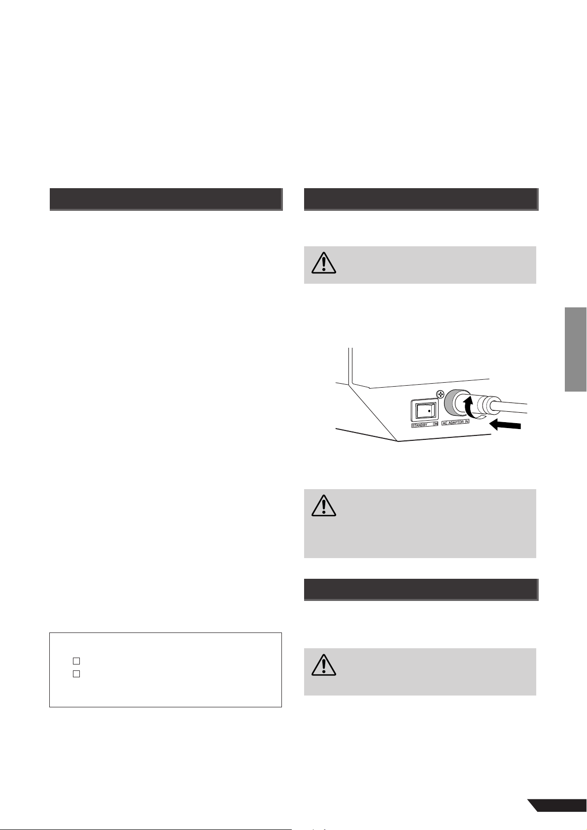
Before Turning on the Mixer
Be sure that the mixer’s power switch is in the
1
STANDBY position.
Use only the PA-20 adaptor included with this mixer.
Use of a different adaptor may result in equipment
damage, overheating, or fire.
Connect the power adaptor to the AC ADAPTOR
2
IN connector (1) on the rear of the mixer, and
then turn the fastening ring clockwise (2) to
secure the connection.
Plug the power adaptor into a standard household
3
power outlet.
Be sure to unplug the adaptor from the outlet when
•
not using the mixer, or when there are lightning
storms in the area.
To avoid generating unwanted noise, make sure
•
there is 50 cm or more between the power adaptor
and the mixer.
Troubleshooting................................. 18
Specifications..................................... 67
Accessories
Owner’s Manual
AC power adaptor (PA-20)
* May not be included depending on your particular
area. Please check with your Yamaha dealer.
*
Turning the Power On
Press the mixer’s power switch to the ON position.
When you are ready to turn the power off, press the
power switch to the STANDBY position.
Note that trace current continues to flow while the
switch is in the STANDBY position. If you do not plan
to use the mixer again for a long while, please be
sure to unplug the adaptor from the wall outlet.
MG124CX/MG124C Owner’s Manual
5
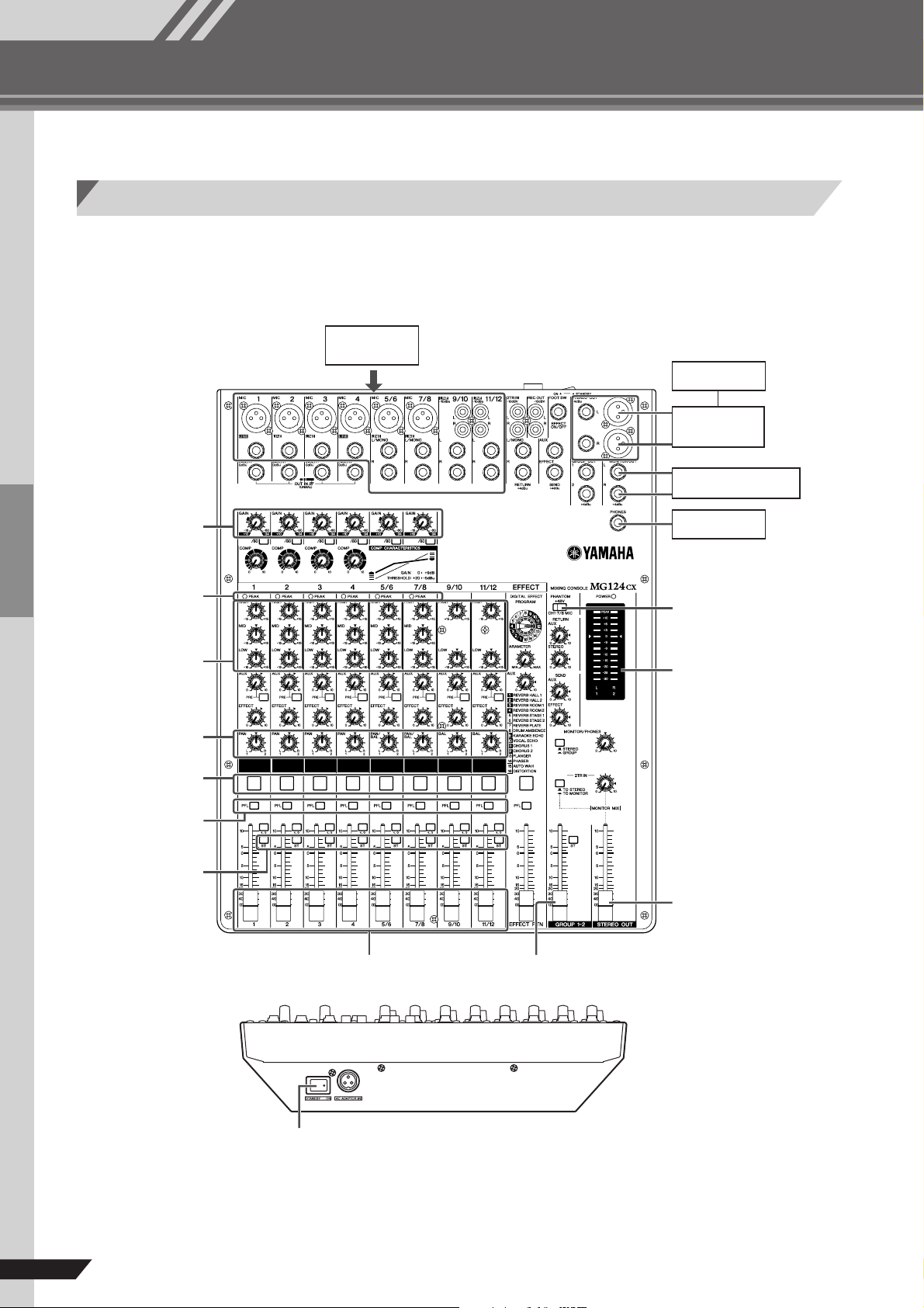
Mixer Basics
Quick Guide
Mixer Basics
Getting Sound to the Speakers
We begin by connecting a pair of speakers and generating some stereo output. Note that operations and procedures will vary somewhat according to the input devices you are using.
2
Microphones,
instruments
Speakers
Power Amp
2
1, 4
GAIN controls
4
PEAK indicators
Equalizer
PA N
5 ON switches
4 PFL switches
5 ST switches
ON ON ON ON ON ON ON ON ON
Monitor Speakers
Headphones
3
PHANTOM switch
4, 7
Level meter
2, 4
2, 4
1, 6, 7
STEREO OUT
Master fader
1, 7 Channel faders
1 GROUP 1-2 fader
1, 3
POWER switch
6
MG124CX/MG124C Owner’s Manual
Mixer Basics
Quick Guide
Be sure that your mixer is turned off
1
and that all level* controls are turned
all the way down.
* STEREO OUT Master Fader, Channel Fader,
GROUP 1-2 Fader, Gain Control, etc.
NOTE
Set the equalizer and the pan controls to their t positions.
Turn off any other external devices,
2
then connect microphones, instruments, and speakers.
NOTE
*For information on connecting external devices see
the Connection Example on page 11.
* Connect electric guitars and basses through an
intermediary device such as a direct box, preamp,
or amp simulator. Connecting these instruments
directly to the MG mixer may result in degraded
sound and noise.
To avoid damage to your speakers,
3
power up the devices in the following
order: Peripheral devices →→
mixer →→
speakers). Reverse this order when
turning power off.
→→
power amps (or powered
→→
MG
Turn on the ON and ST switches for
5
each channel you are using.
Set the STEREO OUT Master fader to
6
the “0” position.
Set the Channel faders to create the
7
desired initial balance, then adjust
the overall volume using the STEREO
OUT Master fader.
NOTE
*To use the LEVEL meter to view the level being
applied to the STEREO L/R buses, set the PFL
switch off ( ) and the MONITOR switch to STEREO ( ).
* If the PEAK indicator lights frequently, lower the
Channel faders a little to avoid distortion.
NOTE
If you are using microphones that require phantom
power, turn the MG mixer’s phantom power switch on
before turning on the power to the power amp or powered speakers. See page 15 for more detail.
Adjust the channel GAIN controls so
4
that the corresponding peak indicators flash briefly on the highest peak
levels.
NOTE
To use the LEVEL meter to get an accurate reading of
the incoming signal level, turn the channel PFL switch
on. Adjust the GAIN controls so that the LEVEL meter
indication occasionally rises above the “ t ” (0) level.
Note that the PHONES jack outputs the pre-fader signal
from all channels on which the PFL switch is ON so that
those signals can be monitored via the headphones.
MG124CX/MG124C Owner’s Manual
7
Mixer Basics
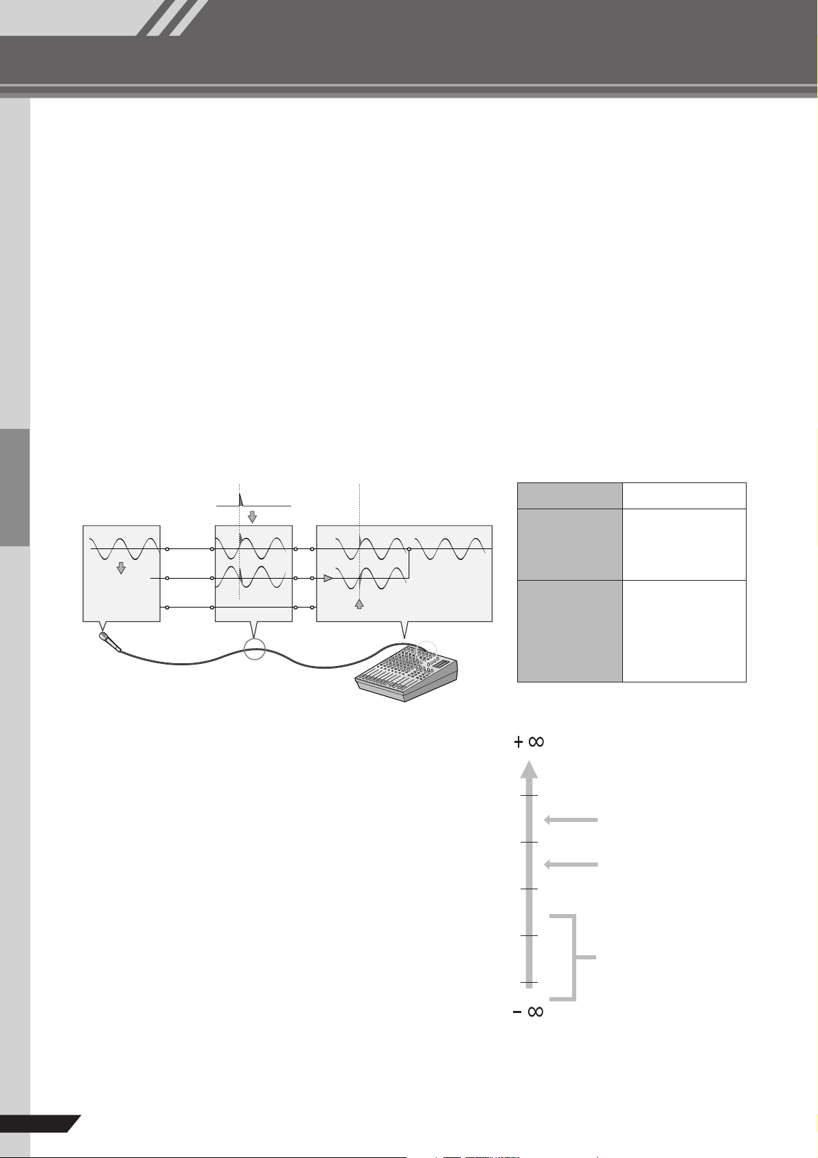
+ 20 dBu
0 dBu
0.775 V
-
20 dBu
-
40 dBu
-
60 dBu
The inputs and outputs on
home-use audio gear
usually have a nominal level
of –10 dBu.
Most professional mixers,
power amplifiers, and other
types of equipment have
inputs and outputs with a
nominal level of +4 dBu.
Microphone signal levels
vary over a wide range
depending on the type of
microphone and the source.
Average speech is about
–30 dBu, but the twittering
of a bird might be lower than
–50 dBu while a solid bass
drum beat might produce a
level as high as 0 dBu.
Making the Most of Your Mixer
You’ve got yourself a mixer and now you’re ready to use it.
Just plug everything in, twiddle the controls, and away you go … right?
Well, if you’ve done this before you won’t have any problems, but if this is the first time you’ve
ever used a mixer you might want to read through this little tutorial and pick up a few basics
that will help you get better performance and make better mixes.
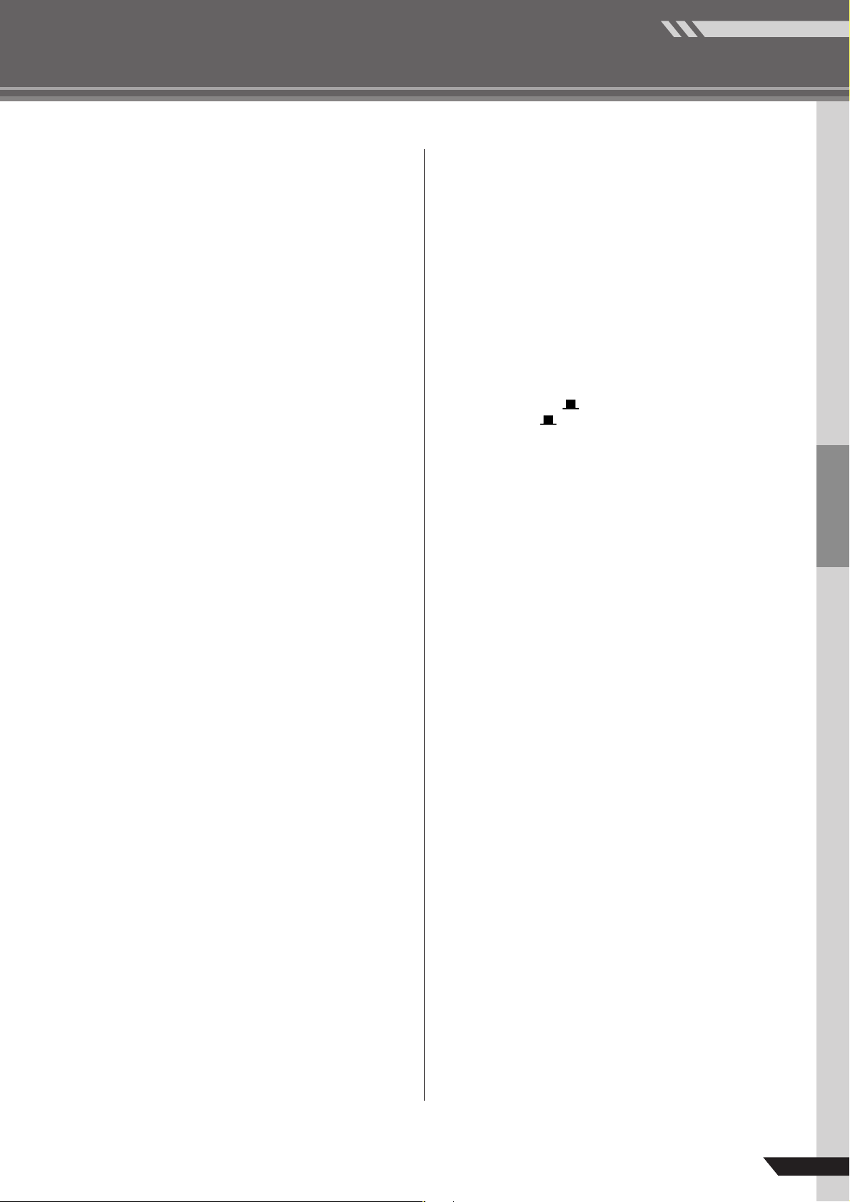
Balanced, Unbalanced—What’s the Difference?
In a word: “noise.” The whole point of balanced lines is noise rejection, and it’s something they’re very good at.
Any length of wire will act as an antenna to pick up the random electromagnetic radiation we’re constantly
surrounded by: radio and TV signals as well as spurious electromagnetic noise generated by power lines,
motors, electric appliances, computer monitors, and a variety of other sources. The longer the wire, the more
noise it is likely to pick up. That’s why balanced lines are the best choice for long cable runs. If your “studio” is
basically confined to your desktop and all connections are no more than a meter or two in length, then
unbalanced lines are fine—unless you’re surrounded by extremely high levels of electromagnetic noise.
Another place balanced lines are almost always used is in microphone cables. The reason for this is that the
output signal from most microphones is very small, so even a tiny amount of noise will be relatively large, and
will be amplified to an alarming degree in the mixer’s high-gain head amplifier.
8
Balanced noise cancellation
Noise
Hot (+)
Cold (–)
Phase
inversion
Source
Ground
Cable
Phase
inversion
Noise cancelled
Receiving device
Noise-free
signal
To summarize
Microphones: Use balanced lines.
Short line-level
runs:
Long line-level
runs:
Unbalanced lines
are fine if you’re in a
relatively noise-free
environment.
The ambient
electromagnetic
noise level will be
the ultimate
deciding factor, but
balanced is best.
Signal Levels and the Decibel
Let’s take a look at one of the most commonly used units in
audio: the decibel (dB). If the smallest sound that can be heard
by the human ear is given an arbitrary value of 1, then the
loudest sound that can be heard is approximately 1,000,000
(one million) times louder. That’s too many digits to deal with
for practical calculations, and so the more appropriate
“decibel” (dB) unit was created for sound-related
measurements. In this system the difference between the
softest and loudest sounds that can be heard is 120 dB. This
is a non-linear scale, and a difference of 3 dB actually results
in a doubling or halving of the loudness.
You might encounter a number of different varieties of the dB:
dBu, dBV, dBM and others, but the dBu is the basic decibel
unit. In the case of dBu, “0 dBu” is specified as a signal level of
0.775 volts. For example, if a microphone’s output level is –40
dBu (0.00775 V), then to raise that level to 0 dBu (0.775 V) in
the mixer’s preamp stage requires that the signal be amplified
by 100 times.
A mixer may be required to handle signals at a wide range of levels, and it is necessary match input and output
levels as closely as possible. In most cases the “nominal” level for a mixer’s input and outputs is marked on the
panel or listed in the owner’s manual.
MG124CX/MG124C Owner’s Manual
 Loading...