


 Loading...
Level and Pressure
Operating Instructions |
|||||||
VEGATOR 521, 522, 523, 527 |
|||||||
|
|
|
5 |
|
5 |
|
5 |
|
|
0 |
10 |
0 |
10 |
0 |
10 |
|
|
|
max |
|
1 |
|
1 |
|
5 |
|
5 |
|
5 |
|
5 |
0 |
10 |
0 |
10 |
0 |
10 |
0 |
10 |
|
|
|
min |
|
2 |
|
2 |
|
on |
|
on |
|
on |
|
on |
|
521 |
|
522 |
|
523 |
|
527 |
|
|
|
|
|
|
|
p |

Contents
Contents
|
Safety information ........................................................................ |
2 |
|
|
Note Ex area ................................................................................ |
2 |
|
1 |
Product description |
|
|
|
1.1 |
Function and configuration .................................................. |
3 |
|
1.2 |
Types and versions ............................................................. |
3 |
|
1.3 |
Approvals ............................................................................. |
3 |
|
1.5 |
Dimensions ........................................................................... |
6 |
2 |
Mounting |
|
|
|
2.1 |
Mounting instructions ........................................................... |
7 |
3 |
Electrical connection |
|
|
|
3.1 |
Connection instructions ....................................................... |
9 |
|
3.2 |
Connection schematic ......................................................... |
9 |
4 |
Setup |
|
|
|
4.1 |
Indicating and adjustment elements ................................ |
11 |
|
4.2 |
Principle of operation ......................................................... |
13 |
|
4.3 |
Switching point adjustment ............................................... |
14 |
5 |
Diagnostics |
|
|
|
5.1 |
Maintenance ....................................................................... |
21 |
|
5.2 |
Repair .................................................................................. |
21 |
|
5.3 |
Failure rectification ............................................................. |
22 |
Safety information
Please read this manual carefully, and also take note of country-specific installation standards (e.g. the VDE regulations in Germany) as well as all prevailing safety regulations and accident prevention rules.
For safety and warranty reasons, any internal work on the instruments, apart from that involved in normal installation and electrical connection, must be carried out only by qualified VEGA personnel.
Note Ex area
Please note the approval documents (yellow binder), and especially the included safety data sheet.
2 |
VEGATOR |

Product description
1 Product description
1.1 Function and configuration
VEGATOR 521, 522, 523 and 527 level switches are signal conditioning instruments in European size (DIN 41 494) for level detection. Typical applications are overfill protection in vessels and dry run protection or double point control of pumps. Depending on the instrument type, up to 2 sensors with analogue transmission of measured data can be connected to the input. 2 relays (spdt) and 2 floating transistors are available as outputs. All instruments are equipped with a fail-safe relay and transistor. The instruments are provided with fault monitoring and adjustable integration time.
All VEGATORs are available with Ex approvals or as overfill protection systems acc. to WHG and VbF.
Function
VEGATOR signal conditioning instruments enable detection of min./max. levels. The measured data of the sensor are converted into a switching command, and connected instruments can be switched on or switched off. The integrated fault monitoring detects short-circuit or break of the measuring cable as well as selected failures from the transmitter. The failure lamp lights and the output relays and output transistors are deenergised in case of failure.
1.2 Types and versions
VEGATOR 521 (Ex)
Signal conditioning instrument as level switch for single point control. 1 sensor input for capacitive electrodes or pressure transmitters. 1 relay output (spdt) and 1 transistor output with fixed switching hysteresis.
VEGATOR 522 (Ex)
Signal conditioning instrument as level switch for one sensor for double point control. 1 sensor input for capacitive electrodes or pressure transmitters. 1 relay output (spdt) and 1 transistor output with adjustable switching hysteresis.
VEGATOR 523 (Ex)
Signal conditioning instrument as level switch for one sensor for dual single point control.
1 sensor input for capacitive electrodes or pressure transmitters. 2 relay outputs (spdt) and 2 transistor outputs with fixed switching hysteresis.
VEGATOR 527 (Ex)
Signal conditioning instrument as level switch for two sensors for single point control. 2 sensor inputs for capacitive electrodes or pressure transmitters. 2 relay outputs (spdt) and 2 transistor outputs with fixed switching hysteresis.
In case of mains failure, the relays deenergise.
Configuration
For configuration of a measuring system, a VEGATOR and one or two sensors with analogue measured data transmission, e.g. a capacitive electrode or a pressure transmitter are required.
1.3 Approvals
VEGATOR is available with the following approvals:
-explosion protection: respective instrument with intrinsically safe circuit(s) [EEx ia] IIC
-overfill protection acc. to WHG applied for
For these applications, please note the relevant offical documents (test report, test certificates, type approvals and conformity certificates). These are supplied with the respective instrument.
VEGATOR |
3 |

Product description
1.4 Technical data
General
Version |
European size DIN 41 612 |
|
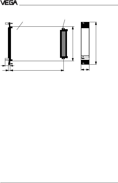
Dimensions |
W = 25.4 mm (5 TE); H = 128.4 mm; D = 162 mm |
|
Weight |
approx. 180 g |
|
Ambient temperature |
-20°C … +60°C |
|
Storage and transport temperature |
-40°C … +70°C |
|
Power supply |
|
|
Operating voltage |
20 … 53 V AC, 50/60 Hz or 20 … 72 V DC |
|
Power consumption |
max. 4 VA |
|
Electrical protective measures |
|
|
Protection class |
II |
|
Overvoltage class |
II |
|
Protection |
|
|
- |
mounted in carrier |
|
|
BGT 596 with module |
IP 00 |
- |
front side completely equipped |
IP 30 |
- |
upper and lower side |
IP 20 (only Ex carrier) |
- |
wiring side (rear) |
IP 00 |
- |
single housing |
IP 20 |
Inputs |
|
|
Transmission |
analogue |
|
Switching threshold |
adjustable 4 … 20 mA |
|
Hysteresis (fixed / min.) |
80 µA |
|
Current limitation |
24 mA (permanently short-circuit proof) |
|
Connection cable to the sensor |
2-wire |
|
Sensor supply voltage |
approx. 15 … 18 V DC |
|
Resistance per wire |
max. 35 Ω |
|
Temperature error |
0.05 %/10 K (relating to range) |
|
Integration time |
0.2 … 20 s |
|
Relay output |
|
|
Number of |
|
|
- |
VEGATOR 521, 522 |
1 level relay |
|
|
1 fail-safe relay |
- |
VEGATOR 523, 527 |
2 level relay |
|
|
1 fail-safe relay |
Modes |
A/B-switch |
|
|
|
A - max. detection or overfill protection |
|
|
B - min. detection or dry run protection |
Contact |
floating spdt |
|
Contact material |
AgNi and Au plated |
|
Turn-on voltage |
min. 10 mV |
|
|
|
max. 250 V AC/DC |
Switching current |
min. 10 µA |
|
|
|
max. 3 A AC, 1 A DC |
Breaking capacitance |
max. 500 VA AC, 54 W DC |
|
|
|
|
4 |
|
VEGATOR |

Product description
Transistor ouput
Number of |
|
|
|
|
|
|
|
|
|
|
|
|
||
- |
VEGATOR 521, 522 |
2 (synchronous switching with relays) |
|
|||||||||||
- |
VEGATOR 523, 527 |
3 (synchronous switching with relays) |
|
|||||||||||
Galvanic separation |
floating |
|
|
|
|
|
|
|
|
|
||||
Operating voltage |
max. 36 V DC |
|
|
|
|
|
|
|
||||||
Operating current |
max. 60 mA |
|
|
|
|
|
|
|
||||||
Transistor voltage loss |
UCE - 1.5 V |
|
|
|
|
|
|
|
||||||
Approvals |
|
|
|
|
|
|
|
|
|
|
|
|
||
VEGATOR 521 Ex, 522 Ex, 523 Ex, 527 Ex |
|
|
|
|
|
|
|
|
|
|
|
|||
with input in classification |
|
|
|
|
|
|
|
|
|
|
|
|
||
Intrinsic safety |
EEx ia IIC, EEx ia IIB |
|
|
|
|
|
||||||||
|
|
|
EEx ib IIC, EEx ib IIB |
|
|
|
|
|
||||||
Max. values |
UO = 20 V |
|
|
|
|
|
|
|
||||||
|
|
|
IK = 126 mA |
|
|
|
|
|
|
|
||||
|
|
|
P = 626 mW |
|
|
|
|
|
|
|
||||
|
Characteristics |
linear |
|
|
|
|
|
|
|
|
|
|||
|
|
|
EEx ia IIC |
|
EEx ia IIB |
|
EEx ib IIC |
|
|
EEx ib IIB |
||||
|
|
|
|
|
|
|||||||||
|
|
|
|
|
|
|
|
|
|
|
|
|
|
|
|
Max. permissible external inductance (mH) |
0.5 |
|
1 |
|
1.5 |
|
2 |
|
2 |
|
|
9 |
|
|
|
|
|
|
|
|
||||||||
|
|
|
|
|
|
|
|
|
|
|
|
|
|
|
|
Max. permissible external capacitance (nF) |
97 |
|
78 |
|
68 |
|
486 |
|
200 |
|
|
1000 |
|
|
|
|
|
|
|
|
|
|
|
|
|
|
|
|
The intrinsically safe circuits are reliably (galvanically) separated from the non-intrinsically safe circuits up to a peak value of the nominal voltage of 375 V.
On instruments with 2 channels (VEGATOR 527 Ex) the intrinsically safe circuits are reliably separated.
CE conformity
VEGATOR 521 Ex, 522 Ex, 523 Ex and 527 Ex signal conditioning instruments meet the protective regulations of EMC (89/336/EW) and NSR (73/23/EWG). Conformity has been judged acc. to the following standards:
EMC Emission Susceptibility
NSR
VEGATOR |
5 |
Product description
1.5 Dimensions
Circuit board 100 x 160 x 1.5 |
Multiple plug |
European size |
100
9 |
|
5,5 |
162 |
5 TE
128,4
on
25,4 |
6 |
VEGATOR |

Mounting
2 Mounting
2.1 Mounting instructions
VEGATOR can be mounted either in a card slot in a carrier BGT 596 or in a single housing type 505.
Card slot
Multipoint connector DIN 41 612, series F, 33pole (d, b, z) with coded pin and mounting material for mounting in carrier BGT 596.
Card slot Ex
Multipoint connector DIN 41 612, series F, 33pole (d, b, z) with coded pins, Ex separating chamber and mounting material for mounting in carrier BGT 596 Ex.M.
Single housing
Plastic housing type 505 for individual mounting of signal conditioning instruments with instrument width 5 TE (25.4 mm).
Mounting carrier
Mount the respective module (standard or Ex version) on your carrier BGT 596. Wire the connections of the multipoint connector according to the connection schematic on the following page.
The multipoint connector is available as follows:
-Wire-Wrap standard connection
1.0x 1.0 mm
-Plug connection 2.8 x 0.8 mm
-Termi-Point standard connection
1.6x 0.8 mm
-Soldering connection
-Screw terminals 2 x 0.5 mm2
For further information on mounting, use the operating instructions of the carrier.
Mounting single housing
The socket can be either screwed directly to the mounting plate or plugged to a carrier rail (TS 35 x 7.5 acc. to EN 50 022 or TS 32 acc. to EN 50 035). Connect the terminals of the basic plate according to the connection schematic on the following page. For further information on mounting, use the operating instructions of the housing.
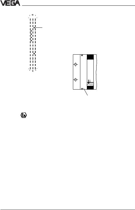
Coding
To prevent inadvertent swapping of the various instruments, the multiple plug of the instrument is provided with one or several coding holes.
By means of a fixed coded pin on the Ex module, it is ensured that only Ex instruments can be inserted.
To prevent inadvertent swapping of the various instruments, two additional coded pins are included with the instrument. Insert these coded pins into the predetermined holes on the multipoint connector. The coded pins must be inserted into the following positions:
|
|
|
|
|
|
VEGATOR 521 |
a9 / c7 |
–– |
|
|
|
VEGATOR 521 Ex |
a9 / c7 |
c23 |
VEGATOR 522 |
a11 / c7 |
–– |
VEGATOR 522 Ex |
a11 / c7 |
c23 |
VEGATOR 523 |
a13 / c7 |
–– |
VEGATOR 523 Ex |
a13 / c7 |
c23 |
VEGATOR 527 |
a15 / c7 |
–– |
VEGATOR 527 Ex |
a15 / c7 |
c23 |
VEGATOR |
7 |
Mounting
|
|
|
|
|
|
z |
|
|
b |
d |
|
|
|
||
|
|
|
|
|
|
|
|
|
|
|
|
|
|
|
|
|
|
|
|
|
|
|
a c |
|
|
|
|
|
|||
|
|
|
|
|
|
|
o 1 o |
|
|
|
|
|
|||
|
|
|
|
|
|
|
o 3 o |
|
|
|
|
|
|||
|
|
|
|
|
|
|
o 5 o |
|
|
|
|
|
|||
|
|
|
|
|
|
|
o 7 o |
|
|
|
c7 |
VEGATOR |
|||
VEGATOR 521 |
a9 |
|
|
|
|
|
o 9 o |
|
|
|
|
|
|||
|
|
|
|
|
|
|
|
|
|
||||||
VEGATOR 522 |
a11 |
|
|
|
|
|
o11o |
|
|
|
|
|
|||
|
|
|
|
|
|
|
|
|
|
||||||
VEGATOR 523 |
a13 |
|
|
|
|
o13o |
|
|
|
|
|
||||
|
|
|
|
|
|
|
|
|
|||||||
VEGATOR 527 |
a15 |
|
|
|
|
o15o |
|
|
|
|
|
||||
|
|
|
|
|
|
|
|
|
|||||||
|
|
|
|
|
|
|
o17o |
|
|
|
|
|
|||
|
|
|
|
|
|
|
o19o |
|
|
|
|
|
|||
|
|
|
|
|
|
|
o21o |
|
|
|
|
|
|||
|
|
|
|
|
|
|
o23o |
|
|
|
|
c23 |
Ex-Codierung |
||
|
|
|
|
|
|
|
|
|
|
|
|||||
|
|
|
|
|
|
|
o25o |
|
|
|
|
|
|||
|
|
|
|
|
|
|
o27o |
|
|
|
|
|
|||
|
|
|
|
|
|
|
o29o |
|
|
|
|
|
|||
|
|
|
|
|
|
|
o31o |
|
|
|
|
|
|||
|
|
|
|
|
|
|
|
|
|
|
|
|
|
|
|
|
|
|
|
|
|
|
|
|
|
|
|
|
|
|
|
|
|
|
|
|
|
|
|
|
|
|
|
|
|
|
|
Transparent cover
To protect the instrument against unauthorized or inadvertent use, the front plate of VEGATOR can be provided with a lockable transparent cover.
Ex version
Ex separating chamber
To ensure sufficient "air and creeping distance", an Ex separating chamber must be mounted to the connections of VEGATOR. Lead the cables through the Ex separating chamber and connect the cables. Fasten the Ex separating chamber with the lower holding screw. Note the operating instructions of the carrier BGT 596 Ex.M.
Mounting in carriers
When mounting VEGATOR with Ex approval in a carrier, a VEGA-Ex card slot must be used. Keep a distance of at least 10 mm
(2 TE) to modules of other manufacturers. When mounting VEGATOR to the complete left position in the carrier, a blind cover of at least 20 mm (4 TE) must be mounted in front of the card slot of the instrument.
2 |
on |
VEGATOR |
Blind cover
Protection for Ex applications
For Ex applications, a protection of IP 20 must be maintained. Cover the gaps or free card slots with blind covers from the front.
8 |
VEGATOR |
Loading...