


5 GHz airMAX® ac Bridge with
500 mm RF Isolated Reflector
Model: PBE-5AC-500-ISO

Introduction
Thank you for purchasing the Ubiquiti Networks®
PowerBeam® ac ISO. This Quick Start Guide is designed to guide you through installation and includes warranty terms.
Package Contents
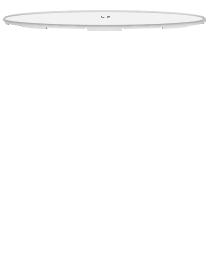
Reflector |
Radome |
Antenna |
Rear Housing |
|
|
Feed |
|
Mounting Bracket |
Adjustment Bracket |
Pole Clamp |
|
|
|
|
(Qty. 2) |
Hex Bolts with Washers |
Flange Nuts |
Carriage Bolts |
(M8x20, Qty. 4) |
(M8, Qty. 4) |
(M8x135, Qty. 4) |
Gigabit PoE (24V, 0.5A) |
Power Cord |
Quick Start Guide |
with Mounting Bracket |
|
|
TERMS OF USE: Ubiquiti radio devices must be professionally installed. Shielded Ethernet cable and earth grounding must be used as conditions of product warranty. TOUGHCable™ is designed for outdoor installations. It is the customer’s responsibility to follow local country regulations, including operation within legal frequency channels, output power, and Dynamic
Frequency Selection (DFS) requirements.
Hardware Overview
Bottom View
Radome
Antenna Feed
Technology
Ethernet Port
Reset Button
Release Button
Reflector

 Mounting Bracket
Alignment Pins
Rear Housing
Release Button Slot
Cable Door

Reset Button To reset to factory defaults, press and hold the
Reset button for more than 10 seconds while the PowerBeam is already powered on. Alternatively, the PowerBeam may be reset remotely via a Reset button located on the bottom of the
Gigabit PoE adapter.
Release Button After you assemble the PowerBeam, check the Release button; it should be fully engaged in the Release Button Slot of the Rear Housing. This ensures that the Antenna Feed is locked into place. If you need to remove the Antenna Feed, you must depress the Release button first.
LEDs
 Signal In airOS, you can modify the wireless signal strength threshold values for each LED on the
Wireless tab under Signal LED Thresholds. The default values are shown below:
 LED will light blue when the wireless signal strength is above -65 dBm.
 LED will light blue when the wireless signal strength is above -73 dBm.
 LED will light blue when the wireless signal strength is above -80 dBm.
 LED will light blue when the wireless signal strength is above -94 dBm.
Ethernet The Ethernet LED will light steady blue when an active Ethernet connection is made and flash when there is activity.
Power The Power LED will light blue when the device is connected to a power source.
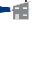
Application Examples
The PowerBeam mounted outdoors with the Reflector installed provides directional outdoor coverage (gain is reflector dependent).
The PowerBeam mounted outdoors without the Reflector installed provides outdoor-to-indoor coverage using the 3 dBi
Antenna Feed only.
Installation Requirements
•13 mm wrench
•Shielded Category 5 (or above) cabling should be used for all wired Ethernet connections and should be grounded through the AC ground of the PoE.
We recommend that you protect your networks from harmful outdoor environments and destructive ESD events with industrial grade, shielded Ethernet cable from Ubiquiti Networks. For more details, visit www.ubnt.com/toughcable

Installation
1.Align and insert the tabs of the Mounting Bracket into the slots of the Reflector. Rotate the Mounting Bracket
counterclockwise until the alignment holes in the dish and bracket align with each other.
2.(Optional) For additional support, insert four M4 screws (not included) into the holes in the Mounting Bracket and
Reflector and secure each screw with two washers and a nut (not included).
3.Line up the Alignment Pins of the Rear Housing with the alignment holes of the Mounting Bracket. Push the Rear Housing into the Mounting Bracket.
4.View the Reflector from the front. Ensure that the three hooks (indicated below) of the Rear Housing are fully engaged with the inner wall of the Reflector and locked into place.
Important: Before proceeding, lightly pull the Rear Housing to confirm that it is locked into place.

5.Push in the sides of the Cable Door and detach it from the
Rear Housing.
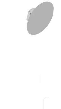
6.Attach the Antenna Feed.
a.Insert the Antenna Feed into the Rear Housing, and push until it locks into place with a click.
b.Lightly pull the Antenna Feed to ensure that it is locked into place and the Release Button is fully engaged.
Release
Button
Bottom View
7.Connect an Ethernet cable to the Ethernet Port of the
Antenna Feed. Then re-attach the Cable Door to the
RearHousing.
8.Attach the Pole Clamps to the Adjustment Bracket.
a.Hold the Adjustment Bracket with its clamps facing you and the Elevation Indicators towards the top.
b.Insert the Carriage Bolts through the holes of the
Adjustment Bracket.
c.Place the Pole Clamps on the bolts on one side of the bracket by sliding the hole of the clamp over the bolt.
d.Place one Flange Nut on each bolt.
Elevation
Indicator
 Loading...