


 Loading...
TL-WR542G
54M Wireless Router
Rev: 1.1.0
1910010140
COPYRIGHT & TRADEMARKS
Specifications are subject to change without notice.  is a registered trademark of TP-LINK TECHNOLOGIES CO., LTD. Other brands and product names are trademarks or registered trademarks of their respective holders.
No part of the specifications may be reproduced in any form or by any means or used to make any derivative such as translation, transformation, or adaptation without permission from TP-LINK TECHNOLOGIES CO., LTD. Copyright © 2009 TP-LINK TECHNOLOGIES CO., LTD. All rights reserved.

FCC STATEMENT
This equipment has been tested and found to comply with the limits for a Class B digital device, pursuant to part 15 of the FCC Rules. These limits are designed to provide reasonable protection against harmful interference in a residential installation. This equipment generates, uses and can radiate radio frequency energy and, if not installed and used in accordance with the instructions, may cause harmful interference to radio communications. However, there is no guarantee that interference will not occur in a particular installation. If this equipment does cause harmful interference to radio or television reception, which can be determined by turning the equipment off and on, the user is encouraged to try to correct the interference by one or more of the following measures:
•Reorient or relocate the receiving antenna.
•Increase the separation between the equipment and receiver.
•Connect the equipment into an outlet on a circuit different from that to which the receiver is connected.
•Consult the dealer or an experienced radio/ TV technician for help.
This device complies with part 15 of the FCC Rules. Operation is subject to the following two conditions:
1)This device may not cause harmful interference.
2)This device must accept any interference received, including interference that may
cause undesired operation.
Any changes or modifications not expressly approved by the party responsible for compliance could void the user’s authority to operate the equipment.
FCC RF Radiation Exposure Statement
This equipment complies with FCC RF radiation exposure limits set forth for an uncontrolled environment. This device and its antenna must not be co-located or operating in conjunction with any other antenna or transmitter.
“To comply with FCC RF exposure compliance requirements, this grant is applicable to only Mobile Configurations. The antennas used for this transmitter must be installed to provide a separation distance of at least 20 cm from all persons and must not be

co-located or operating in conjunction with any other antenna or transmitter.”
CE Mark Warning
This is a class B product. In a domestic environment, this product may cause radio interference, in which case the user may be required to take adequate measures.
National Restrictions
2400.0-2483.5 MHz
Country |
Restriction |
Reason/remark |
Bulgaria |
|
General authorization required for outdoor |
|
|
use and public service |
|
|
|
France |
Outdoor use limited to |
|
10 mW e.i.r.p. within |
|
the band 2454-2483.5 |
|
MHz |
Military Radiolocation use. Refarming of the 2.4 GHz band has been ongoing in recent years to allow current relaxed regulation. Full implementation planned 2012
Italy |
|
If used outside of own premises, general |
|
|
authorization is required |
|
|
|
Luxembourg |
None |
General authorization required for network |
|
|
and service supply(not for spectrum) |
|
|
|
Norway |
Implemented |
This subsection does not apply for the |
|
|
geographical area within a radius of 20 km |
|
|
from the centre of Ny-Ålesund |
|
|
|
Russian |
|
Only for indoor applications |
Federation |
|
|
|
|
|
Note It’s not used outdoors in France.

 TP-LINK TECHNOLOGIES CO., LTD
DECLARATION OF CONFORMITY
For the following equipment:
Product Description: 54M Wireless Router
Model No.: TL-WR542G
Trademark: TP-LINK
We declare under our own responsibility that the above products satisfy all the technical regulations applicable to the product within the scope of Council Directives:
Directives 1999/5/EC
The above product is in conformity with the following standards or other normative documents:
ETSI EN 300 328 V1.7.1: 2006
ETSI EN 301 489-1 V1.8.1:2008 & ETSI EN 301 489-17 V1.3.2:2008 EN 61000-3-2:2006
EN 61000-3-3:1995+A1:2001 EN60950-1:2006 EN50371:2002
Directives 2004/108/EC
The above product is in conformity with the following standards or other normative documents
EN 55022:2006
EN 55024:1998+A1:2001+A2:2003 EN 61000-3-2:2006
EN 61000-3-3:1995+A1:2001+A2:2005
Directives 2006/95/EC
The above product is in conformity with the following standards or other normative documents EN60950-1:2006
Person is responsible for marking this declaration:
Zhao Jianjun
Director of International Business
TP-LINK TECHNOLOGIES CO., LTD.
South Building, No.5 Keyuan Road, Central Zone, Science & Technology Park,
Nanshan,
Shenzhen, P. R. China
|
|
CONTENTS |
|
Package Contents ..................................................................................................... |
1 |
||
Chapter |
1.Introduction........................................................................................... |
2 |
|
1.1 |
Overview of the Router ................................................................................................ |
2 |
|
1.2 |
Features ............................................................................................................................... |
2 |
|
1.3 |
Panel Layout ...................................................................................................................... |
3 |
|
1.3.1 The Front Panel............................................................................................................ |
3 |
||
1.3.2 The Rear Panel............................................................................................................. |
4 |
||
Chapter |
2.Connecting the Router ...................................................................... |
6 |
|
2.1 |
System Requirements.................................................................................................... |
6 |
|
2.2 |
Installation Environment Requirements................................................................ |
6 |
|
2.3 |
Connecting the Router.................................................................................................. |
6 |
|
Chapter |
3.Quick Installation Guide................................................................... |
8 |
|
3.1 |
TCP/IP configuration...................................................................................................... |
8 |
|
3.2 |
Quick Installation Guide ............................................................................................. |
10 |
|
Chapter |
4.Configuring the Router ................................................................... |
13 |
|
4.1 |
Login.................................................................................................................................... |
13 |
|
4.2 |
Status.................................................................................................................................. |
14 |
|
4.3 |
Quick Setup...................................................................................................................... |
15 |
|
4.4 |
Network.............................................................................................................................. |
16 |
|
4.4.1 LAN................................................................................................................................... |
16 |
||
4.4.2 WAN................................................................................................................................. |
16 |
||
4.4.3 MAC Clone .................................................................................................................... |
27 |
||
4.5 |
Wireless.............................................................................................................................. |
28 |
|
4.5.1 Wireless Settings ....................................................................................................... |
28 |
||
4.5.2 MAC Filtering ............................................................................................................... |
33 |
||
4.5.3 Wireless Statistics...................................................................................................... |
36 |
||
4.6 |
DHCP ................................................................................................................................... |
37 |
|
4.6.1 DHCP Settings............................................................................................................. |
37 |
||
4.6.2 DHCP Clients List....................................................................................................... |
38 |
||
4.6.3 Address Reservation ................................................................................................ |
39 |
||
4.7 |
Forwarding........................................................................................................................ |
40 |
|
4.7.1 Virtual Servers ............................................................................................................ |
40 |
||
4.7.2 Port Triggering............................................................................................................ |
42 |
||
4.7.3 DMZ ................................................................................................................................. |
44 |
||
4.7.4 UPnP................................................................................................................................ |
45 |
||
4.8 |
Security .............................................................................................................................. |
46 |
|
4.8.1 Firewall........................................................................................................................... |
46 |
||
4.8.2 IP Address Filtering .................................................................................................. |
47 |
||
4.8.3 Domain Filtering......................................................................................................... |
49 |
||
4.8.4 MAC Address Filtering ............................................................................................. |
50 |
||
4.8.5 Advanced Security .................................................................................................... |
52 |
||
4.9 |
Static Routing.................................................................................................................. |
54 |
|
4.10 |
IP QoS................................................................................................................................. |
56 |
|
4.11 IP & MAC Binding Setting.......................................................................................... |
57 |
||
4.11.1 |
Binding Setting....................................................................................................... |
58 |
|
4.11.2 |
ARP List...................................................................................................................... |
59 |
|
4.12 |
DDNS................................................................................................................................... |
60 |
|
4.12.1 |
Dyndns.org DDNS................................................................................................. |
60 |
|
4.12.2 |
Oray.net DDNS....................................................................................................... |
61 |
|
4.12.3 |
Comexe.cn DDNS.................................................................................................. |
62 |
|
4.13 |
System Tools ................................................................................................................... |
63 |
|
4.13.1 |
Time ............................................................................................................................ |
64 |
|
4.13.2 |
Firmware ................................................................................................................... |
65 |
|
4.13.3 |
Factory Defaults..................................................................................................... |
66 |
|
4.13.4 |
Backup & Restore.................................................................................................. |
66 |
|
4.13.5 |
Reboot........................................................................................................................ |
67 |
|
4.13.6 |
Password................................................................................................................... |
67 |
|
4.13.7 |
Syslog ......................................................................................................................... |
68 |
|
4.13.8 |
Remote Management.......................................................................................... |
69 |
|
4.13.9 |
Statistics .................................................................................................................... |
69 |
|
Appendix A: FAQ...................................................................................................... |
72 |
||
Appendix B: Configuring the PCs ..................................................................... |
77 |
||
Appendix C: Specifications.................................................................................. |
81 |
||
Appendix D: Glossary ............................................................................................ |
82 |
||
Package Contents
The following contents should be found in your box:
¾One TL-WR542G 54Mbps Wireless Router
¾One AC power Adapter for TL-WR542G 54Mbps Wireless Router
¾Quick Installation Guide
¾One Resource CD for TL-WR542G 54Mbps Wireless Router, including:
•This Guide
•Other Helpful Information
) Note:
Make sure that the package contains the above items. If any of the listed items are damaged or missing, please contact with your distributor.
Conventions
The router or TL-WR542G mentioned in this guide stands for TL-WR542G 54Mbps Wireless Router without any explanation.
1
Chapter 1. Introduction
Thank you for choosing TL-WR542G 54Mbps Wireless Router.
1.1 Overview of the Router
The TL-WR542G 54Mbps Wireless Router integrates 4-port Switch, Firewall, NAT-router and Wireless AP. Its design is dedicated to Small Office/Home Office (SOHO) wireless network solutions. The TL-WR542G 54Mbps Wireless Router will allow you to connect your network wirelessly better than ever, sharing Internet Access, files and fun, easily and securely.
In the most attentive wireless security, the TL-WR542G 54Mbps Wireless Router provides multiple protection measures. It can be set to turn off wireless network name (SSID) broadcast so that only stations that have the SSID can be connected. The router provides wireless LAN 64/128/152-bit WEP encryption security, and WPA/WPA2 and WPA-PSK/WPA2-PSK authentication, as well as TKIP/AES encryption security. It also supports VPN pass-through for sensitive data secure transmission.
The TL-WR542G 54Mbps Wireless Router complies with the IEEE 802.11g and IEEE 802.11b standards so that the data transmission rate is up to 54Mbps. It adopts 2x to 3x eXtended Range™ WLAN transmission technology so that the transmission distance is 2-3 times of traditional IEEE 802.11g and IEEE 802.11b solutions, up to a distance of 855.36m tested in China. The transmission range is extended to 4-9 times. It is compatible with all IEEE 802.11g and IEEE 802.11b products.
The TL-WR542G 54Mbps Wireless Router provides flexible access control so that parents or network administrators can establish restricted access policies for children or staff. It has built-in NAT and DHCP server supporting static IP address distributing. It also supports Virtual Server and DMZ host for Port Triggering needs, and remote management and log so that network administrators can manage and monitor the network in real time. This device supports Bridge mode which can make two APs communicate with each other wirelessly.
The TL-WR542G 54Mbps Wireless Router is easy-to-manage. Quick Setup is supported and friendly help messages are provided for every step. So you can configure it quickly and share Internet access, files and fun.
1.2Features
¾Complies with IEEE 802.11g, IEEE 802.11b, IEEE 802.3, IEEE 802.3u standards.
¾1 10/100M Auto-Negotiation RJ45 WAN port, 4 10/100M Auto-Negotiation RJ45 LAN ports, supporting Auto MDI/MDIX.
¾Adopts 2x to 3x eXtended Range™ wireless LAN transmission technology.
2
¾Supports 54/48/36/24/18/12/9/6Mbps or 11/5.5/3/2/1Mbps data transfer rates.
¾Provides WPA/WPA2, WPA-PSK/WPA2-PSK authentication, TKIP/AES encryption security.
¾Shares data and Internet access for users, supporting PPPoE, Dynamic IP, Static IP, L2TP, PPTP, Big Pond Cable Internet access.
¾Supports Virtual Server, Special Application and DMZ host.
¾Supports UPnP, Dynamic DNS, Static Routing, VPN Pass-through.
¾Detachable reverse SMA connector Antenna.
¾Connecting Internet on demand and disconnecting from the Internet when idle for PPPoE.
¾Built-in NAT and DHCP server supporting static IP address distributing.
¾Built-in firewall supporting IP address filtering, Domain Name filtering, and MAC address filtering.
¾Supports connecting/disconnecting from the Internet on a specified time of day.
¾Supports access control, parents and network administrators can establish restricted access policies based on time of day for children or staff.
¾Provides 64/128/152-bit WEP encryption security and wireless LAN ACL (Access Control List).
¾Supports Flow Statistics.
¾Supports ICMP-FLOOD, UDP-FLOOD, and TCP-SYN-FLOOD filter.
¾Ignores Ping packets from WAN or LAN ports.
¾Supports firmware upgrade.
¾Supports Web management.
1.3Panel Layout
1.3.1The Front Panel
The Router’s LEDs are located on the front panel (View from left to right). Table 1-1 describes the LEDs on the front panel of the router.
3
|
|
|
|
|
Figure 1-1 Front Panel sketch |
|
Name |
|
Status |
|
Indication |
|
|
|
|
|
|
|
PWR |
|
Off |
No Power |
|
|
|
|
|
|
|
|
|
On |
|
Power on |
|
|
|
|
|
||
|
|
|
|
|
|
|
|
|
Off |
The Router has an error |
|
|
SYS |
|
|
|
|
|
|
On |
|
The Router is initializing |
|
|
|
|
|
|
|
|
|
|
Flashing |
The Router is working properly |
|
|
|
|
|
|
|
|
WLAN |
|
Off |
The Wireless function is disabled |
|
|
|
|
|
|
|
|
|
Flashing |
The Wireless function is enabled |
||
|
|
|
|||
|
|
|
|
|
|
|
|
|
Off |
There is no device linked to the corresponding port |
|
|
|
|
|
|
|
|
WAN/1-4 (LAN) |
|
On |
|
There are devices linked to the corresponding ports but no data |
|
|
|
transmitted or received. |
||
|
|
|
|
|
|
|
|
|
|
|
|
|
|
|
Flashing |
Sending or receiving data over corresponding port |
|
|
|
|
|
|
|
|
|
|
|
|
Table 1-1 The LEDs description |
1.3.2 The Rear Panel
The following parts are located on the rear panel (View from left to right).
¾ AC power socket: Please use the power adapter which is supplied with the TL-WR542G 54Mbps Wireless Router only, the use of a different adapter may result in product damage.
4
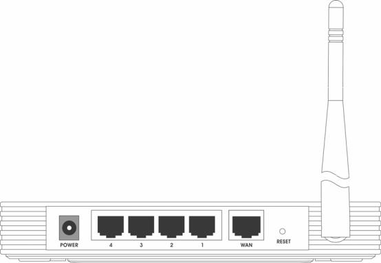
¾ LAN 1,2,3,4: Four 10/100Mbps RJ45 LAN ports for connecting the router to the local PC(s)
¾ WAN: This WAN port is where you will connect the cable/DSL Modem, or Ethernet
¾Reset button:
There are two ways to reset the router's factory defaults:
1)Use the Factory Defaults function on System Tools -> Factory Defaults page in the router's Web-based Utility.
2)Use the Factory Default Reset button: With the router powered on, use a pin to press and hold the Reset button(about 5 seconds) until the SYS LED becomes quick-flash from slow-flash. And then release the button and wait the router to reboot to its factory default settings.
) Note: Ensure the router is powered on before it restarts completely.
¾Wireless antenna
Figure 1-2 Rear Panel sketch
5
Chapter 2. Connecting the Router
2.1System Requirements
¾Broadband Internet Access Service (DSL/Cable/Ethernet)
¾One DSL/Cable modem that has an RJ45 connector (you do not need it if you connect the router to the Ethernet)
¾Each PC in the LAN needs a working Ethernet Adapter and an Ethernet cable with RJ45 connectors
¾TCP/IP protocol must be installed on each PC
¾Web browser, such as Microsoft Internet Explorer 5.0 or later, Netscape Navigator 6.0 or later
2.2Installation Environment Requirements
¾Do not place in direct sunlight or near a heater or heating vent
¾Do not cluttered or crowded. There should be at least 2 inches (5 cm) of clear space on all sides of the router
¾Well ventilated (especially if it is in a closet)
¾Operating temperature: 0 ~40 (32 ~104 )
¾Operating Humidity: 10%~90%RH, Non-condensing
2.3Connecting the Router
Before you install the router, you should connect your PC to the Internet through your broadband service successfully. If there is any problem, please contact your ISP. After that, please install the router according to the following steps. Don't forget to pull out the power plug and keep your hands dry.
1.Power off your PC, Cable/DSL Modem, and the router.
2.Locate an optimum location for the router. The best place is usually near the center of the
area in which your PC will connect wirelessly. The place must accord with the Installation Environment Requirements.
3.Adjust the direction of the antenna. Normally, upright is a good direction.
4.Connect the PC(s) and each Switch/Hub in your LAN to the LAN Ports on the router, shown in Figure 2-1. (If you have the wireless NIC and want to use wireless function, you can skip this step.)
6
5.Connect the DSL/Cable Modem to the WAN port on the router, shown in Figure 2-1.
6.Connect the AC power adapter to the AC power socket on the router, and the other end into an electrical outlet. The router will start to work automatically.
7.Power on your PC and Cable/DSL Modem.
Figure 2-1 Hardware Installation of the TL-WR542G 54Mbps Wireless Router
7
Chapter 3. Quick Installation Guide
After connecting the TL-WR542G Router into your network, you should configure it. This chapter describes how to configure the basic functions of your TL-WR542G Wireless Router. These procedures only take you a few minutes. You can access the Internet via the router immediately after successfully configuring.
3.1 TCP/IP configuration
The default IP address of the TL-WR542G 54Mbps Wireless Router is 192.168.1.1. And the default Subnet Mask is 255.255.255.0. These values can be seen from the LAN. They can be changed as you desire, as an example we use the default values for description in this guide.
Connect the local PC to the LAN ports of the router. There are then two ways to configure the IP address for your PC.
¾Configure the IP address manually
1)Set up the TCP/IP Protocol for your PC. If you need instructions as to how to do this, please refer to Appendix B: "Configuring the PC."
2)Configure the network parameters. The IP address is 192.168.1.xxx ("xxx" is from 2 to 254), Subnet Mask is 255.255.255.0, and Gateway is 192.168.1.1 (The router's default IP address)
¾Obtain an IP address automatically
1)Set up the TCP/IP Protocol in "Obtain an IP address automatically" mode on your PC. If you need instructions as to how to do this, please refer to Appendix B: "Configuring the PC."
2)Power off the router and PC. Then turn on the router and restart the PC. The built-in DHCP server will assign IP address for the PC.
) Note: For Windows 98 OS or earlier, the PC and router may need to be restarted.
Now, you can run the Ping command in the command prompt to verify the network connection between your PC and the router. The following example is in Windows 2000 OS.
Open a command prompt, and type ping 192.168.1.1, and then press Enter.
If the result displayed is similar to that shown in Figure 3-1, the connection between your PC and the router has been established.
8

Figure 3-1 Success result of Ping command
If the result displayed is similar to that shown in Figure 3-2, it means that your PC has not connected to the router.
Figure 3-2 Failure result of Ping command
Please check the connection following these steps:
1.Is the connection between your PC and the router correct?
) Note:
The 1/2/3/4 LEDs of LAN port which you link to on the router and LEDs on your PC's adapter should be lit.
2.Is the TCP/IP configuration for your PC correct?
) Note:
9

If the router's IP address is 192.168.1.1, your PC's IP address must be within the range of 192.168.1.2 ~ 192.168.1.254, the gateway must be 192.168.1.1.
3.2 Quick Installation Guide
With a Web-based (Internet Explorer or Netscape® Navigator) utility, it is easy to configure and manage the TL-WR542G 54Mbps Wireless Router. The Web-based utility can be used on any Windows, Macintosh or UNIX OS with a Web browser.
Connect to the router by typing http://192.168.1.1 in the address field of Web browser.
Figure 3-3 Login the router
After a moment, a login window will appear similar to that shown in Figure 3-4. Enter admin for the User Name and Password, both in lower case letters. Then click the OK button or press the
Enter key.
Figure 3-4 Login Windows
) Note:
If the above screen does not pop-up, it means that your Web-browser has been set to a proxy. Go to Tools menu>Internet Options>Connections>LAN Settings, in the screen that appears, cancel the Using Proxy checkbox, and click OK to finish it.
If the User Name and Password are correct, you can configure the router using the Web browser. Please click the Quick Setup link on the left of the main menu and the Quick Setup screen will appear.
10

Figure 3-5 Quick Setup
Click Next, and then Choose WAN Connection Type page will appear, shown in Figure 3-6.
Figure 3-6 Choose WAN Connection Type
The router supports three popular ways to connect to Internet. Please select one compatible with your ISP. Click Next to enter the necessary network parameters.
If you choose "PPPoE", you will see this page shown in Figure 3-7:
Figure 3-7 Quick Setup - PPPoE
¾Account Name and Password - Enter the Account Name and Password provided by your ISP. These fields are case sensitive. If you have difficulty with this process, please contact your ISP.
If you choose "Dynamic IP", the router will automatically receive the IP parameters from your ISP without needing to enter any parameters.
If you Choose "Static IP", the Static IP settings page will appear, shown in Figure 3-8:
11
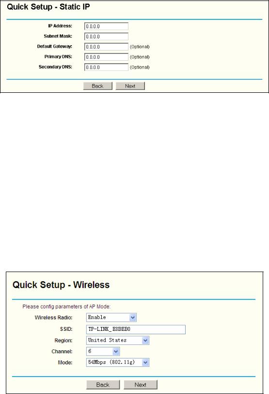
Figure 3-8 Quick Setup - Static IP
) Note: The IP parameters should have been provided by your ISP.
¾IP Address - This is the WAN IP address as seen by external users on the Internet (including your ISP). Enter the IP address into the field.
¾Subnet Mask - The Subnet Mask is used for the WAN IP address, it is usually 255.255.255.0
¾Default Gateway - Enter the gateway IP address into the box if required.
¾Primary DNS - Enter the DNS Server IP address into the boxes if required.
¾Secondary DNS - If your ISP provides another DNS server, enter it into this field.
After you complete the above, click Next, the Wireless settings page will appear, shown in Figure 3-9.
Figure 3-9 Quick Setup - Wireless settings
In this page, you can configure the following wireless parameters:
¾Wireless Radio - Indicates whether the Access Point feature of the router is enabled or disabled. If disabled, the WLAN LED on the front panel will not be lit and the wireless
12

stations will not be able to access the router. If enabled, the WLAN LED will be lit up and wireless stations will be able to access the router.
¾SSID - Enter a value of up to 32 characters. The same SSID must be assigned to all wireless devices on your network. The default SSID is TP-LINK_XXXXXX(XXXXXX indicates the last unique six characters of each Router’s MAC address). This value is case-sensitive. For example, TP-LINK is NOT the same as tp-link.
¾Region - Select your region from the pull-down list. This field specifies the region where the wireless function of the router can be used. It may be illegal to use the wireless function of the router in a region other than one of those specified in this field.
¾Channel - The current channel in use. This field determines which operating frequency will be used.
¾Mode - Indicates the current mode 54Mbps (802.11g), 11Mbps (802.11b). If you select
54Mbps (802.11g), it is compatible with 11Mbps (802.11b).
These settings are only for basic wireless parameters, for advanced settings, please refer to Section 4.5: "Wireless."
) Note:
The change of wireless settings won't take effect until the router reboots! You can reboot it manually. If you need instructions as to how to do this, please refer to Section 4.12.5: "Reboot”.
Click the Next button. You will then see the Finish page:
Figure 3-10 Quick Setup - Finish
After finishing all configurations of basic network parameters, please click Finish button to exit this Quick Setup.
Chapter 4. Configuring the Router
This chapter describes each Web page's key functions.
4.1 Login
After your successful login, you can configure and manage the router. There are twelve main
13
menus on the left of the Web-based utility. Submenus will be available after you click one of the main menus. The twelve main menus are: Status, Quick Setup, Network, Wireless, DHCP,
Forwarding, Security, Static Routing, IP QoS, IP & MAC Binding Setting, DDNS and System Tools. On the right of the Web-based utility, there are the detailed explanations and instructions for the corresponding page. To apply any settings you have altered on the page, please click the Save button.
The detailed explanations for each Web page key’s function are listed below.
4.2 Status
The Status page displays the router's current status and configuration. All information is read-only.
1.LAN
This field displays the current settings or information for the LAN, including the MAC address,
IP address and Subnet Mask.
2.Wireless
This field displays basic information or status for wireless function, including Wireless Radio,
SSID, Channel, Mode, Wireless MAC address, and IP address.
3.WAN
These parameters apply to the WAN port of the router, including MAC address, IP address, Subnet Mask, Default Gateway, DNS server and WAN connection type. If PPPoE is chosen as the WAN connection type, the Disconnect button will be shown here while you are accessing the Internet. You can also cut the connection by clicking the button. If you have not connected to the Internet, just click Connect to establish the connection.
Traffic Statistics
This field displays the router's traffic statistics.
4.System Up Time
The total up time of the router from when it was switched on or reset.
14

Figure 4-1 Router Status
4.3 Quick Setup
Please refer to Section 3.2: "Quick Installation Guide."
15
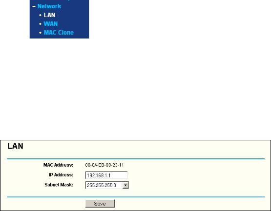
4.4 Network
Figure 4-2 the Network menu
There are three submenus under the Network menu (shown in Figure 4-2): LAN, WAN and MAC Clone. Click any of them, and you will be able to configure the corresponding function. The detailed explanations for each submenu are provided below.
4.4.1 LAN
You can configure the IP parameters of LAN on this page.
Figure 4-3 LAN
¾MAC Address - The physical address of the router, as seen from the LAN. The value can't be changed.
¾IP Address - Enter the IP address of your router in dotted-decimal notation (factory default: 192.168.1.1).
¾Subnet Mask - An address code that determines the size of the network. Normally use 255.255.255.0 as the subnet mask.
) Note:
If you change the IP Address of LAN, you must use the new IP Address to login the router.
If the new LAN IP Address you set is not in the same subnet, the IP Address pool of the DHCP server will not take effect, until they are re-configured.
If the new LAN IP Address you set is not in the same subnet, the Virtual Server and DMZ Host will change accordingly at the same time.
4.4.2 WAN
You can configure the WAN port parameters on this page.
16

First, please choose the WAN Connection Type (Dynamic IP/Static IP/PPPoE/802.1X + Dynamic IP/802.1X + Static IP/Big Pond Cable/L2TP/PPTP) for Internet. The default type is Dynamic IP. If you aren’t given any login parameters (fixed IP Address, logging ID, etc), please select Dynamic IP. If you are given a fixed IP (static IP), please select Static IP. If you are given a user name and a password, please select the type of your ISP provided (PPPoE/BigPond/L2TP/PPTP). If you are not sure which connection type you use currently, please contact your ISP to obtain the correct information.
1.If you choose Dynamic IP, the router will automatically get IP parameters from your ISP. You can see the page as follows (Figure 4-4):
Figure 4-4 WAN – Dynamic IP
This page displays the WAN IP parameters assigned dynamically by your ISP, including IP address, Subnet Mask, Default Gateway, etc. Click the Renew button to renew the IP parameters from your ISP. Click the Release button to release the IP parameters.
MTU Size - The normal MTU (Maximum Transmission Unit) value for most Ethernet networks is 1500 Bytes. For some ISPs you need to reduce the MTU. But this is rarely required, and should not be done unless you are sure it is necessary for your ISP connection.
If your ISP gives you one or two DNS addresses, select Use These DNS Servers and enter the primary and secondary addresses into the correct fields. Otherwise, the DNS servers will be assigned dynamically from your ISP.
) Note:
17

If you get address and find error when you go to a Web site, it is likely that your DNS servers are set up improperly. You should contact your ISP to get DNS server addresses.
Get IP with Unicast DHCP - A few ISPs' DHCP servers do not support the broadcast applications. If you cannot get the IP Address normally, you can choose this option. (This is rarely required.)
2.If you choose Static IP, you should have fixed IP Parameters specified by your ISP. The Static IP settings page will appear, shown in Figure 4-5:
Figure 4-5 WAN - Static IP
You should type the following parameters into the spaces provided:
¾IP Address - Enter the IP address in dotted-decimal notation provided by your ISP.
¾Subnet Mask - Enter the subnet Mask in dotted-decimal notation provided by your ISP, usually is 255.255.255.0.
¾Default Gateway - (Optional) Enter the gateway IP address in dotted-decimal notation provided by your ISP.
¾MTU Size - The normal MTU (Maximum Transmission Unit) value for most Ethernet networks is 1500 Bytes. For some ISPs you may need to modify the MTU. But this is rarely required, and should not be done unless you are sure it is necessary for your ISP connection.
¾Primary DNS - (Optional) Enter the DNS address in dotted-decimal notation provided by your ISP.
¾Secondary DNS - (Optional) Type another DNS address in dotted-decimal notation provided by your ISP if provided.
3.If you choose PPPoE, you should enter the following parameters (Figure 4-6):
18

Figure 4-6 WAN - PPPoE
¾User Name/Password - Enter the User Name and Password provided by your ISP. These fields are case-sensitive.
¾Connect on Demand - You can configure the router to disconnect your Internet connection after a specified period of inactivity (Max Idle Time). If your Internet connection has been terminated due to inactivity, Connect on Demand enables the router to automatically re-establish your connection as soon as you attempt to access the Internet again. If you wish to activate Connect on Demand, click the radio button. If you want your Internet connection to remain active at all times, enter 0 in the Max Idle Time field. Otherwise, enter the number of minutes you want to have elapsed before your Internet connection terminates.
Caution: Sometimes the connection cannot be disconnected although you specify a time to Max Idle Time, since some applications is visiting the Internet continually in the background.
¾Connect Automatically - Connect automatically after the router is disconnected. To use this option, click the radio button.
¾Time-based Connecting - You can configure the router to make it connect or disconnect based on time. Enter the start time in HH:MM format for connecting and end time in HH:MM format for disconnecting in the Period of Time fields.
) Note:
Only when you have configured the system time on System Tools -> Time page, will the
19

Time-based Connecting function can take effect.
¾Connect Manually - You can configure the router to make it connect or disconnect manually. After a specified period of inactivity (Max Idle Time), the router will disconnect from the Internet connection, and you will not be able to re-establish your connection automatically as soon as you attempt to access the Internet again. To use this option, click the radio button. If you want your Internet connection to remain active at all times, enter "0" in the Max Idle Time field. Otherwise, enter the number time in minutes that you wish to have the Internet connecting last unless a new link is requested.
Caution: Sometimes the connection cannot be disconnected although you specify a time to Max Idle Time, since some applications are visiting the Internet continually in the background.
Click the Connect button to connect immediately. Click the Disconnect button to disconnect immediately.
Click the Advanced Settings button to set up the advanced option, the page shown in Figure 4-7 will then appear:
Figure 4-7 PPPoE Advanced Settings
¾Packet MTU - The default MTU size is 1480 bytes, which value is usually fine. For some ISPs, you need modify the MTU. This should not be done unless you are sure it is necessary for your ISP.
¾Service Name/AC Name - The service name and AC (Access Concentrator) name, these should not be configured unless you are sure it is necessary for your ISP.
¾ISP Specified IP Address - If you know that your ISP does not automatically transmit your IP
20
Loading...