


 Loading...

COPYRIGHT & TRADEMARKS
Specifications are subject to change without notice.  is a registered trademark of TP-LINK Technologies Co., Ltd. Other brands and product names are trademarks or registered trademarks of their respective holders.
No part of the specifications may be reproduced in any form or by any means or used to make any derivative such as translation, transformation, or adaptation without permission from TP-LINK Technologies Co., Ltd. Copyright © 2006 TP-LINK Technologies Co., Ltd. All rights reserved.
FCC STATEMENT
This equipment has been tested and found to comply with the limits for a class B digital device, pursuant to part 15 of the FCC Rules. These limits are designed to provide reasonable protection against harmful interference in a residential installation.
This equipment generates, uses and can radiate radio frequency energy and, if not installed and used in accordance with the instructions, may cause harmful interference to radio communications. However, there is no guarantee that interference will not occur in a particular installation. If this equipment does cause harmful interference to radio or television reception, which can be determined by turning the equipment off and on, the user is encouraged to try to correct the interference by one or more of the following measures:
•Reorient or relocate the receiving antenna.
•Increase the separation between the equipment and receiver.
•Connect the equipment into an outlet on a circuit different from that to which the receiver is connected.
•Consult the dealer or an experienced radio/TV technician for help.
CE Mark Warning
This is a Class B product. In a domestic environment, this product may cause radio interference, in which case the user may be required to take adequate measures.
EC DECLARATION OF CONFORMITY (EUROPE)
In compliance with the EMC Directive 89/336/EEC, Low Voltage Directive 73/23/EEC, this product meets the requirements of the following standards:
•EN55022
•EN55024
•EN60950
SAFETY NOTICES
Caution: Do not use this product near water, for example, in a wet basement or near a swimming pool.
Avoid using this product during an electrical storm. There may be a remote risk of electric shock from lightning.
Package contents.............................................................................................................. |
2 |
|
Chapter 1: Product Overview ............................................................................................ |
3 |
|
1.1 |
Product main specification ................................................................................... |
3 |
1.2 |
Supporting protocol.............................................................................................. |
3 |
1.3 Transmit data-rate................................................................................................ |
4 |
|
1.4 ATM property........................................................................................................ |
4 |
|
1.5 |
System support .................................................................................................... |
4 |
1.6 |
Working environment ........................................................................................... |
4 |
1.7 |
Electric parameter................................................................................................ |
4 |
Chapter 2: Hardware Installation Guide ............................................................................ |
5 |
|
2.1 |
System requirement............................................................................................. |
5 |
2.2 |
LED explanation................................................................................................... |
5 |
2.3 |
Rear-panel ........................................................................................................... |
5 |
2.4 |
Hardware installation procedures figure2-1 ................................................... |
6 |
Chapter 3: System Configuration ...................................................................................... |
7 |
|
3.1 |
Computer Configuration....................................................................................... |
7 |
3.2 |
Login .................................................................................................................... |
8 |
3.3 |
Web Setup ......................................................................................................... |
10 |
3.4 |
Software Dial...................................................................................................... |
19 |
3.5 |
USB Configuration ............................................................................................. |
20 |
Chapter 4: Advantage management setup...................................................................... |
23 |
|
Chapter 5: FQA............................................................................................................... |
24 |
|
Appendix A: Default Configuration .................................................................................. |
25 |
|
Appendix B: Contact Information..................................................................................... |
26 |
|

TD-8811 External ADSL2+ Router User Guide
Package contents
The following contents should be found in your box:
¾One TD-8811 External ADSL2+ ROUTER
¾One AC power Adapter for TD-8811 External ADSL2+ ROUTER
¾One Resource CD for TD-8811 External ADSL2+ ROUTER, including:
• This Guide
• Quick installation Guide Program
• Other Helpful Information
• USB driver
¾Quick installation Guide
¾One RJ45 cable
¾Two RJ11 cable
¾One ADSL splitter
¾One USB cable
Note: If any of the above items are damaged or missing, please contact the retailer from whom you purchased the TD-8811 External ADSL2+ ROUTER for assistance.
- 2 -

TD-8811 External ADSL2+ Router User Guide
Chapter 1: Product Overview
TP-LINK® TD-8811 External ADSL ROUTER is the latest product designed and manufactured by TP-LINK Technologies Co., Ltd. With TP-LINK’s excellent circuit design and high quality production, we guarantee the ADSL ROUTER’s high performance, great stability and easy to use.
TD-8811 uses integrated ADSL2+ transceiver and a 256-MHz MIPS32 CPU, the AFE supports full-rate ADSL connectivity conforming to the ITU and ANSI specifications; MIPS32 CPU with MMU and 16-KB I-cache/8-KB D-cache is integrated into the device.
In addition to the basic DMT physical layer functions, the ADSL PHY supports dual latency ADSL framing (fast and interleaved) and the I.432 ATM Physical Layer.
The TD-8811 is a complete plug-and-play solution. With standard Ethernet interface, it can be directly connected to any 10M/100M Ethernet devices, support Auto-MDIX.
The TD-8811 not only uses html (web mode through Ethernet port) to configure the ROUTER but also uses external utility software too. You can download it from our website (http://www.tp-link.com).
1.1 Product main specification
¾Adopts the high performance IC which integrates the AFE transceiver and the 256 MHZ MIPS32 CPU, guaranteeing that this product is efficient and steady.
¾High speed and asymmetrical data transmit mode, provides safe and exclusive bandwidth
¾Supports All ADSL industrial standards
¾Compatible with all mainstream DSLAM (CO)
¾Firmware upgradeable
¾Provides integrated access of internet and route function which face to SOHO user
¾Advanced DMT modulation and demodulation
¾Real-time Configuration and device monitoring
¾Quick response semi-conductive surge protection circuit, provides reliable ESD and surge-protect function
1.2 Supporting protocol
-G.992.1 (G.dmt) - Annex A/B/C
-G.992.2 (G.lite) - Annex A/B/C
-ANSI T1.413
-G.992.3 (ADSL2) - Annex A/B/C/M and Annex L (RE-DSL) compliant
-G.992.5 (ADSL2+) Annex A/B/C and Annex L (RE-DSL) compliant
-ADSL dual latency (fast path and interleaved path)
-I.432 ATM physical layer compliant
-Supports RFC2364 (PPPoA)
- 3 -

TD-8811 External ADSL2+ Router User Guide
-Supports RFC2516 (PPPoE)
-Supports RFC1483 (EoA)(Bridged *and route) -Supports RFC1577 (IPoA)
NOTE. “*” Needs the third-party software.
1.3 Transmit data-rate
¾ Max download data-rate: 24Mbps ¾ Max upload data-rate: 1Mbps
¾ Max line length: 6Km
1.4 ATM property
¾ AAL0, AAL5, OAM, RM, and raw cell types supported
¾ Direct hardware support for 4 Receive VCs, with additional RX VCs and TX VCs supported in software
¾ Full 24-bit Virtual Path Identifier (VPI) and Virtual Circuit Identifier (VCI)
1.5 System support
¾Support PVC
¾Support NAT DHCP and so on
¾Support IEEE 802.3 IEEE 802.3u
¾Support 10Base-T/100BASE-TX full-duplex or half duplex Ethernet
¾Support Auto-MDIX
¾Support USB 1.1 device interface
1.6 Working environment
¾Operating temperature: 0 ~40
¾Storage temperature: -40 ~70
¾Humidity: 10%~90% (non-condensing)
1.7 Electric parameter
¾Adaptor power Output: 9VAC/0.8A 50Hz or 60 Hz
¾Power consumption: 4W Maximum
- 4 -

TD-8811 External ADSL2+ Router User Guide
Chapter 2: Hardware Installation Guide
The TD-8811 maintains three separate interfaces, one Ethernet ,one USB interface and one ADSL interface. The Router should not be located where it will be exposed to moisture or excessive heat. Place the Router in a location where it can be safely connected to the various devices as well as to a power source.
2.1 System requirement
Confirm your computer has been installed with networking interface card (NIC) before connecting ADSL2+ ROUTER to your computer, with the operating system supporting the TCP/IP protocol.
2.2 LED explanation
The front panel of ADSL2+ ROUTER includes one power indicator (RED) and five function indicators (GREEN), as explained in chart 1-1:
Indicator |
Description |
Status |
Function Details |
|
PWR |
Power |
On |
Power OK |
|
Off |
Power fail |
|||
|
|
|||
|
|
Slow flash |
Self-detecting when power up |
|
ADSL |
ADSL status |
Quick flash |
Connecting to the telecom network |
|
|
|
On |
Connection to telecom network OK |
|
|
|
On |
There is mistake when ADSL transmitting data or |
|
ALARM |
Mistake |
|
receiving data |
|
|
|
Off |
ADSL normal |
|
|
|
On |
There is data transmitting or receiving on WAN |
|
ACT |
Data |
|
port |
|
|
|
Off |
No data transmitting or receiving on WAN port |
|
|
|
On |
Connection to telecom network OK |
|
USB |
USB status |
Off |
Connect on USB port abnormal |
|
|
|
Flash |
Data transmitting or receiving |
|
|
|
On |
LAN port normal |
|
LAN |
Ethernet |
Off |
Connection on LAN port abnormal |
|
|
|
Flash |
Data transmitting or receiving on LAN port |
|
|
|
|
|
|
|
|
|
Chart 1-1 |
2.3 Rear-panel
¾ON/OFF: Turn on/off the ADSL2+ ROUTER’s power.
¾Power (9VAC/0.8A input): please do not use any unknown power adaptor,
-5 -
TD-8811 External ADSL2+ Router User Guide
otherwise your ADSL2+ ROUTER may be damaged.
¾RESET(reset default): First press the reset button of ROUTER, then turn on the ROUTER’s power for at least three seconds. It will resume the default manufacturer’s setup.
¾LAN: Connect with your computer’s NIC.
¾USB: Connect with your computer’s USB interface
¾LINE(WAN): Connect to the MODEM Port of Splitter or Connecting the telephone line.
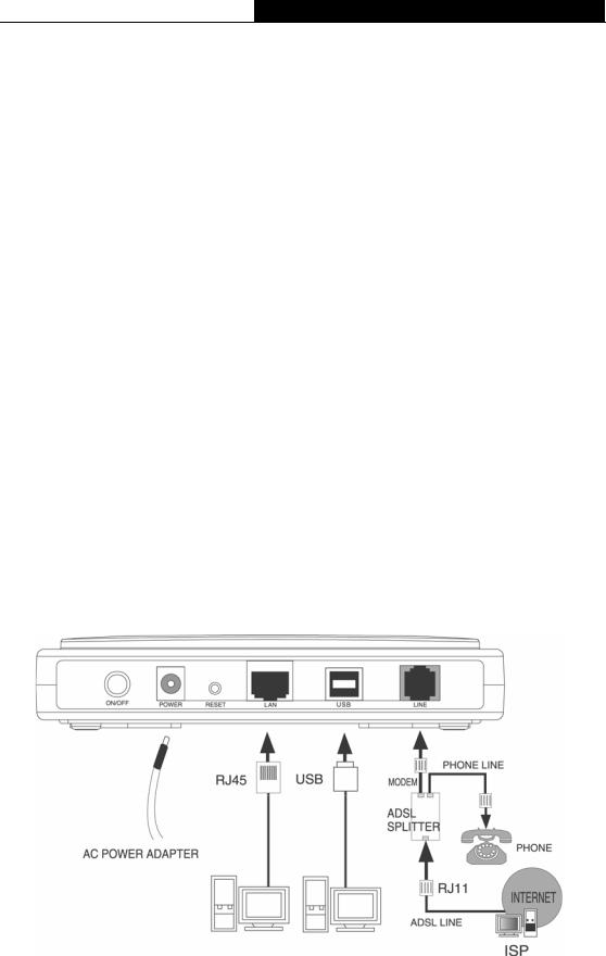
2.4 Hardware installation procedures figure2-1
The procedure to install the Router can be described in general terms in the following steps:
First Step: Connecting the MODEM port of Splitter with the LINE port of the TD-8811 ADSL2+ ROUTER by telephone line. While you need to use a telephone, please attach telephone line into the phone of Splitter.
Second Step: Connect category 5 cable with RJ45 jacks to ADSL2+ ROUTER’s LAN port and your computer’s NIC. Or connect USB cable to ADSL2+ ROUTER’s USB port and your computer’s USB interface
Third Step: Plug one end of the AC Power Adapter into the Power jack on the Ethernet ADSL2+ ROUTER and the other end to a standard electrical outlet.
Last Step: Check the line connection to see if everything is ready. Power up finally.
Figure2-1
- 6 -
TD-8811 External ADSL2+ Router User Guide
Chapter 3: System Configuration
3.1 Computer Configuration
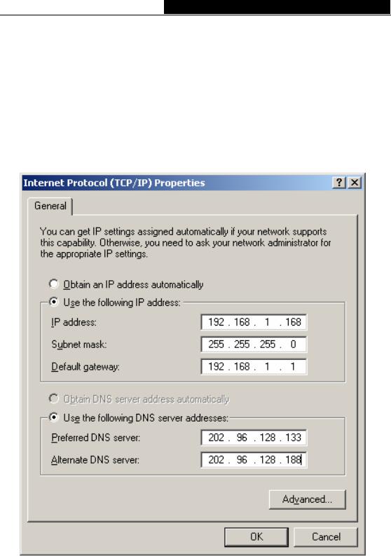
1.Connect the cable according to Chapter 2, turn on the power.
2.Change the IP address of your PC Figure 3-1 : Open TCP/IP Properties of the LAN card in your PC, enter the IP address as 192.168.1.* (* is any value between 2 to 254, Net mask is 255.255.255.0, Gateway is 192.168.1.1, DNS address is the value provided by ISP).
Figure 3-1
Please note:
Users of Windows 98 can open TCP/IP Properties according to the following: Right-click (Mouse) Network Neighbor -> Choose Properties -> Double-click TCP/IP PCI Fast Ethernet Adapter.
- 7 -
Loading...