


Schneider Electric TAC Xenta 280, TAC Xenta 300, TAC Xenta 401 Users Manual
TAC Vista
TAC Pangaea
WorkStation
TAC Xenta 280/300/401
Product Manual

TAC Vista
TAC Xenta 280/300/401
Product Manual
Copyright © 2007-2011 Schneider Electric Buildings AB. All rights reserved.
This document, as well as the product it refers to, is only intended for licensed users. Schneider Electric Buildings AB owns the copyright of this document and reserves the right to make changes, additions or deletions. Schneider Electric Buildings AB assumes no responsibility for possible mistakes or errors that might appear in this document.
Do not use the product for other purposes than those indicated in this document.
Only licensed users of the product and the document are permitted to use the document or any information therein. Distribution, disclosure, copying, storing or use of the product, the information or the illustrations in the document on the part of non-licensed users, in electronic or mechanical form, as a recording or by other means, including photo copying or information storage and retrieval systems, without the express written permission of Schneider Electric Buildings AB, will be regarded as a violation of copyright laws and is strictly prohibited.
Trademarks and registered trademarks are the property of their respective owners.

TAC Xenta, TAC Xenta 280/300/401 |
Contents |
|
|
Contents
INTRODUCTION
1 About this Manual |
9 |
|
1.1 |
Structure ..................................................................................................................... |
9 |
1.2 |
Typographic Conventions .......................................................................................... |
10 |
1.3 |
Prerequisites ............................................................................................................... |
10 |
REFERENCE
2 TAC Xenta Components |
13 |
|
2.1 |
Hardware Units .......................................................................................................... |
13 |
2.2 |
Configurations............................................................................................................ |
14 |
2.3 |
Communications ........................................................................................................ |
15 |
3 Technical Description |
17 |
|
3.1 |
The TAC Xenta 280 Controller.................................................................................. |
17 |
3.1.1 |
Terminals.................................................................................................................... |
17 |
3.1.2 |
Jacks ........................................................................................................................... |
18 |
3.1.3 |
LED Indicators and Service pin ................................................................................. |
19 |
3.1.4 |
Technical Data TAC Xenta 280................................................................................. |
20 |
3.2 |
The TAC Xenta 300 Controller.................................................................................. |
21 |
3.2.1 |
Terminals.................................................................................................................... |
21 |
3.2.2 |
Jacks ........................................................................................................................... |
23 |
3.2.3 |
LED Indicators and Service pin ................................................................................. |
23 |
3.2.4 |
Technical Data TAC Xenta 300................................................................................. |
24 |
3.3 |
The TAC Xenta 401 Controller.................................................................................. |
25 |
3.3.1 |
Terminals.................................................................................................................... |
25 |
3.3.2 |
Jacks ........................................................................................................................... |
25 |
3.3.3 |
LED Indicators and Service pin ................................................................................. |
26 |
3.3.4 |
Technical Data TAC Xenta 401................................................................................. |
27 |
4 Installation |
29 |
|
4.1 |
Mounting the Controller............................................................................................. |
29 |
4.2 |
Electrical Installation ................................................................................................. |
30 |
4.2.1 |
General Considerations .............................................................................................. |
30 |
4.2.2 |
Cabinet Connections .................................................................................................. |
32 |
4.2.3 |
Cables......................................................................................................................... |
34 |
4.3 |
Terminations .............................................................................................................. |
39 |
4.3.1 |
The TAC Xenta OP Operator Panel........................................................................... |
42 |
5 Configuring your System |
45 |
|
5.1 |
Overview .................................................................................................................... |
45 |
Schneider Electric Buildings AB, June 2011 |
5 (74) |
04-00067-02-en |
|

Contents |
|
TAC Xenta, TAC Xenta 280/300/401 |
|
|
|
|
|
|
5.2 |
A Single TAC Xenta 280/300/401 Controller............................................................ |
46 |
|
5.2.1 |
Initial Check ............................................................................................................... |
46 |
|
5.2.2 |
OP Panel Activities..................................................................................................... |
47 |
|
5.3 |
Two or more TAC Xenta 280/300/401 Units............................................................. |
47 |
|
5.3.1 |
Initial Check ............................................................................................................... |
47 |
|
5.3.2 |
Device Configuration ................................................................................................. |
47 |
|
5.3.3 |
OP Panel Activities..................................................................................................... |
48 |
|
5.4 |
Additional I/O Units ................................................................................................... |
48 |
|
5.4.1 |
Selecting I/O Modules................................................................................................ |
48 |
|
5.4.2 |
Initial Check ............................................................................................................... |
49 |
|
5.4.3 |
I/O Module Configuration.......................................................................................... |
49 |
|
5.5 |
Setting the Date and Time .......................................................................................... |
50 |
|
5.6 |
Clearing the Xenta Application .................................................................................. |
51 |
|
5.7 |
Lock a Xenta OP to a specific TAC Xenta Controller ............................................... |
51 |
|
5.7.1 |
Creating the PVI-block in the Xenta .......................................................................... |
51 |
|
5.7.2 |
Enabling the function in TAC Xenta OP.................................................................... |
52 |
6 |
The TAC Xenta Service Menu |
53 |
|
|
6.1 |
Accessing the Service Menu ...................................................................................... |
53 |
|
6.2 |
Submenus 1-8 ............................................................................................................. |
54 |
|
6.2.1 |
Submenu 6: Test dial .................................................................................................. |
57 |
APPENDIX |
|
|
|
A |
Appendix A Restart Values |
63 |
|
B |
Appendix B Restart Sequences |
67 |
|
Index |
|
71 |
|
6 (74) |
Schneider Electric Buildings AB, June 2011 |
|
04-00067-02-en |
INTRODUCTION
1 About this Manual

TAC Xenta, TAC Xenta 280/300/401 |
1 About this Manual |
|
|
1 About this Manual
This manual describes a particular process. For information on certain products, we refer you to the manual or the Help for the product in question.
For information on how to install software, we refer you to the instructions delivered with the software.
For information on third party products, we refer you to the instructions delivered with the third party product.
If you discover errors and/or unclear descriptions in this manual, please contact your Schneider Electric representative.
Note
•We are continuously improving and correcting our documentation. This manual may have been updated.
Please check our Docnet site at www.tac.com for the latest version.
1.1Structure
The manual is divided into the following parts:
•Introduction
The Introduction section contains information on how this manual is structured and how it should be used to find information in the most efficient way.
•Reference
The Reference section contains more comprehensive information about various parts of the Getting Started section. It also provides you with information on alternative solutions not covered by the Getting Started section.
Schneider Electric Buildings AB, June 2011 |
9 (74) |
04-00067-02-en |
|
1 About this Manual |
TAC Xenta, TAC Xenta 280/300/401 |
|
|
1.2Typographic Conventions
Throughout the manual the following specially marked texts may occur.
!Warning
•Alerts you that failure to take, or avoid, a specific action might result in physical harm to you or to the hardware.
Caution
•Alerts you to possible data loss, breaches of security, or other more serious problems.
Important
•Alerts you to supplementary information that is essential to the completion of a task.
Note
•Alerts you to supplementary information.
Tip
•Alerts you to supplementary information that is not essential to the completion of the task at hand.
Advanced
•Alerts you that the following information applies to complex tasks or tasks restricted by access.
1.3Prerequisites
To be able to profit from the contents in this manual, it is recommended that you read the following documents:
•TAC Xenta 280 Programmable Controller datasheet
•TAC Xenta 300 Programmable Controller datasheet
•TAC Xenta 400 Controller, freely programmable datasheet
10 (74) |
Schneider Electric Buildings AB, June 2011 |
|
04-00067-02-en |
REFERENCE
2TAC Xenta Components
3Technical Description
4Installation
5Configuring your System
6The TAC Xenta Service Menu
TAC Xenta, TAC Xenta 280/300/401 |
2 TAC Xenta Components |
|
|
2 TAC Xenta Components
2.1Hardware Units
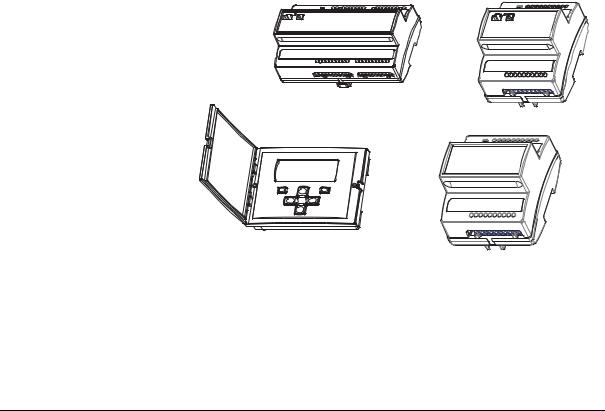
The TAC Xenta 280/300/400 family consists of the following units:
•The TAC Xenta 280/300/401 controller. The controller contains the database of the inputs and outputs of the TAC Xenta system. It also contains the system and application software for all the functions that are to be performed by the controller and the connected peripheral units.
•TAC Xenta OP. The operator panel includes control buttons while a screen displays the values and menus. TAC Xenta OP can be connected to any controller in the network.
I/O expansion modules. These can be used to extend the number of inputs and outputs on a TAC Xenta 300/401 controller.
The I/O modules are described in a separate manual, TAC Xenta 400 I/ O Modules.
TAC Xenta 280 or 300 controller |
12 13 14 15 16 |
17 18 |
20 |
|
|
|
TAC Xenta 401 controller
Operator panel |
12 13 14 15 16 17 18 |
20 |
|
|
I/O expansion module
Fig. 2.1: The basic units of the TAC Xenta: the controller, the operator panel, and an I/O expansion module
Schneider Electric Buildings AB, June 2011 |
13 (74) |
04-00067-02-en |
|

2 TAC Xenta Components |
TAC Xenta, TAC Xenta 280/300/401 |
|
|
|
|
Inputs |
Outputs |
I/O Modules |
See section |
|
|
|
|
|
|
TAC Xenta 280 |
|
|
|
|
3.1 |
|
TAC Xenta 281 |
6 |
6 |
none |
|
|
TAC Xenta 282 |
8 |
8 |
none |
|
|
TAC Xenta 283 |
6 |
6 |
none |
|
TAC Xenta 300 |
|
|
|
|
3.2 |
|
TAC Xenta 301 |
12 |
8 |
up to 2 |
|
|
TAC Xenta 302 |
12 |
8 |
up to 2 |
|
TAC Xenta 401 |
|
none |
none |
up to 10 |
3.3 |
|
|
|
|
|
|
A number of controllers and I/O modules can form a local network and exchange data.
The TAC Xenta OP operator panel allows the user to:
•Obtain access to certain parameters
•Monitor the system status
•Adjust setpoints and time channels
•Display alarms (without communicating with a central system) Up to two OPs may be connected to each controller.
2.2Configurations
The TAC Xenta controllers can be used in different configurations, for example:
•As stand-alone units (for a TAC Xenta 401 with at least one I/O module).
•With controllers and OPs in a network, with extra I/O modules as required (no I/O modules for the TAC Xenta 280).
•With controllers, OPs, I/O modules and other equipment in a full network with suitable adapters, possibly with connections to a TAC Vista Central System.
14 (74) |
Schneider Electric Buildings AB, June 2011 |
|
04-00067-02-en |
TAC Xenta, TAC Xenta 280/300/401 |
2 TAC Xenta Components |
|
|
|
TAC |
TAC |
Web |
Management |
Vista |
Vista |
Browser |
|
|
|
|
level |
|
|
IP Network |
PCLTA |
or |
|
|
card |
|
|
|
|
|
|
|
|
TAC Xenta 901 |
TP/FT-10 |
TAC Xenta 511 |
Automation |
|
|
|
level |
|
|
|
TAC Xenta OP |
|
TAC Xenta OP |
|
|
TAC Xenta 401 |
I/O Module I/O Module |
TAC Xenta 281 TAC Xenta 301 |
Field |
|
+ |
- |
level |
|
||
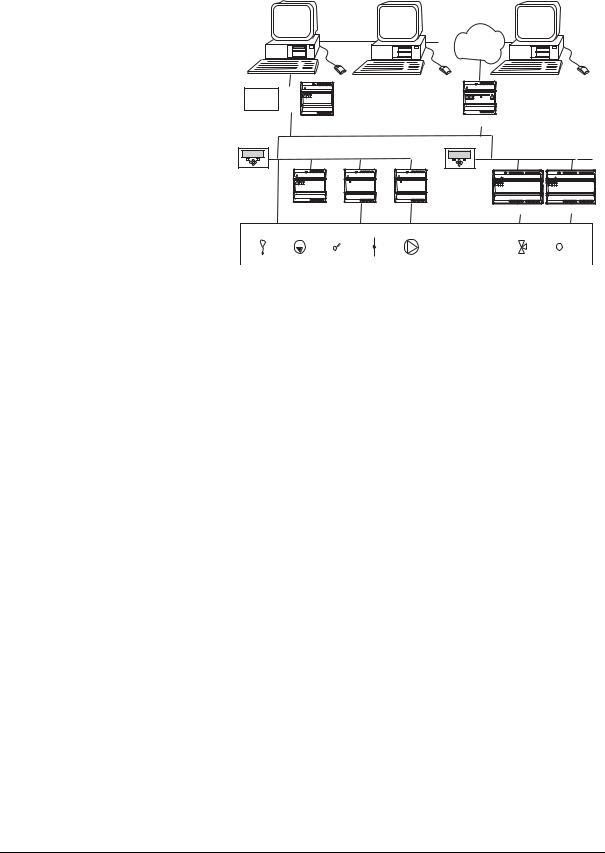
Fig. 2.2: A TAC Xenta network example
2.3Communications
The TAC Xenta units communicate with each other in a network using a common bus, Echelon® LONWORKS® Free Topology 78 kbps (FTT10). Additional I/O units also connect to the network and may be added as required. An I/O unit can only be associated with one controller.
Explicit LONTALK® messages are used in communications between the operator panel and the controller.
The LONTALK protocol makes it possible to use Network Variables, defined on foreign equipment.
The Functional Block applications are modeled as true LONMARK Controller Objects.
The Network Variable interface (including the Standard Network Variable Types, SNVTs) can be customized, and External Interface Files (XIFs) can be generated in the field using the TAC Menta tool. Available SNVTs are listed in an appendix to the Engineering Applications in TAC Menta manual.
When connected to a TAC Vista Central System, the operating conditions of equipment such as fans, pumps, and recovery units can be displayed as graphs on the monitor and printed as reports. All temperatures and alarms may be read, while setpoints and time settings may be altered as required
TAC Xenta controllers can be reached from TAC Vista in many ways. Using LonWorks in the Xenta controller, some examples are:
•From a PCLTA card in some form, directly on the PC.
Schneider Electric Buildings AB, June 2011 |
15 (74) |
04-00067-02-en |
|

2 TAC Xenta Components |
TAC Xenta, TAC Xenta 280/300/401 |
|
|
•Via the LTA function in the TAC Xenta 911.
•Via the LTA function in the TAC Xenta 511.
•Using the TAC Xenta 901.
•Via an Ethernet/LON gateway.
Using the serial channel in the Xenta controller, for example:
•Directly connected to a PC serial channel.
•Connected to a PC serial channel via a telephone modem.
•Connected to a PC serial channel via the IP modem function of the TAC Xenta 911.
Starting from v 3.1, application programs generated in TAC Menta may be downloaded from TAC Vista via the network.
The TAC Xenta 280/300/401 can communicate as follows:
•It can send alarm and trend logging (versions 3.2 and higher) messages.
•It can answer requests for the status of inputs and outputs.
•It can send/ any of the parameters/variables in the program which are freely available (“Public signal”).
•It can communicate with other TAC Xenta controllers to exchange data.
•It can communicate with the Operator Panel, the I/O-modules, and TAC Vista.
For further details, please consult the TAC Vista IV, Engineering Classic/LNS Network manuals.
RS232
The TAC Xenta 280/300/401 controller has an RS232 port that can be used to:
•Load the system software.
•Load the application software from the TAC Menta programming tool.
•Connect to TAC Menta when used as a commissioning tool.
•Connect a specific controller directly to TAC Vista or via a modem (modem connection not available with TAC Xenta 280).
•Retrieve the “System Error Log File” using the “Xenta System Error Log Viewer”.
16 (74) |
Schneider Electric Buildings AB, June 2011 |
|
04-00067-02-en |
TAC Xenta, TAC Xenta 280/300/401 |
3 Technical Description |
|
|
3 Technical Description
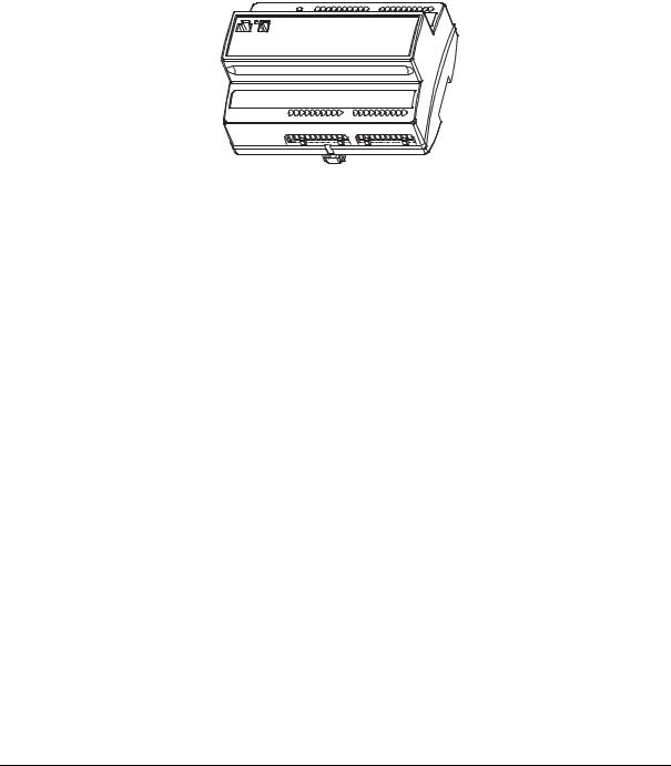
3.1The TAC Xenta 280 Controller
Fig. 3.1: The TAC Xenta 280 controller
3.1.1Terminals
The TAC Xenta 281, 282 and 283
The TAC Xenta 280 has three I/O configurations, called the TAC Xenta 281, 282, and 283.
No external TAC Xenta 400 I/O modules can be used.
|
Digital |
Thermistor |
Univer- |
Relay |
TRIAC |
Analog |
|
inputs |
inputs |
sal inputs |
outputs |
outputs |
outputs |
|
|
|
|
|
|
|
Term. notation |
X |
B |
U |
K |
V |
Y |
TAC Xenta 281 |
2 |
- |
4 |
3 |
- |
3 |
TAC Xenta 282 |
2 |
2 |
4 |
4 |
- |
4 |
TAC Xenta 283 |
2 |
4 |
- |
- |
6 |
- |
|
|
|
|
|
|
|
Schneider Electric Buildings AB, June 2011 |
17 (74) |
04-00067-02-en |
|
3 Technical Description |
TAC Xenta, TAC Xenta 280/300/401 |
|
|
<![endif]>Comm
|
|
|
|
max 230 V AC |
||
|
|
20 |
40 |
|
|
|
|
M |
19 |
39 |
|
|
|
|
|
18 |
38 |
KC2 |
|
|
|
X2 |
17 |
37 |
K3 |
|
|
|
M |
16 |
36 |
K2 |
|
|
|
X1 |
15 |
35 |
KC1 |
|
|
|
|
14 |
34 |
K1 |
|
|
|
|
13 |
33 |
|
|
|
|
|
12 |
32 |
|
|
|
|
|
11 |
31 |
|
|
|
|
|
10 |
30 |
|
|
|
|
|
9 |
29 |
|
|
|
|
U4 |
8 |
28 |
|
|
|
|
M |
7 |
27 |
M |
|
|
|
U3 |
6 |
26 |
Y3 |
|
|
|
U2 |
5 |
25 |
Y2 |
|
|
|
M |
4 |
24 |
M |
|
|
{ |
U1 |
3 |
23 |
Y1 |
0 |
24 V |
C2 |
2 |
22 |
G0 |
|||
C1 |
1 |
21 |
G |
~ |
}AC/DC |
|
<![endif]>Comm
M
X2
M
X1
M
B2
M
B1
U4
M
U3
U2
M
U1 { C2C1
C2C1
|
|
max 230 V AC |
||
20 |
40 |
|
|
|
19 |
39 |
K4 |
|
|
18 |
38 |
KC2 |
|
|
17 |
37 |
K3 |
|
|
16 |
36 |
K2 |
|
|
15 |
35 |
KC1 |
|
|
14 |
34 |
K1 |
|
|
13 |
33 |
|
|
|
12 |
32 |
|
|
|
11 |
31 |
|
|
|
10 |
30 |
|
|
|
9 |
29 |
|
|
|
8 |
28 |
Y4 |
|
|
7 |
27 |
M |
|
|
6 |
26 |
Y3 |
|
|
5 |
25 |
Y2 |
|
|
4 |
24 |
M |
|
|
3 |
23 |
Y1 |
0 |
24 V |
2 |
22 |
G0 |
||
1 |
21 |
G |
~ |
}AC/DC |
<![endif]>Comm
|
|
|
|
|
|
24 V AC |
|
|
20 |
40 |
VC |
|
|
|
M |
19 |
39 |
V4 |
|
|
|
|
18 |
38 |
|
|
|
|
X2 |
17 |
37 |
V3 |
|
|
|
M |
16 |
36 |
V2 |
|
|
|
X1 |
15 |
35 |
|
|
|
|
B4 |
14 |
34 |
V1 |
|
|
|
M |
13 |
33 |
V6 |
|
|
|
B3 |
12 |
32 |
|
|
|
|
B2 |
11 |
31 |
V5 |
|
|
|
M |
10 |
30 |
|
|
|
|
B1 |
9 |
29 |
|
|
|
|
|
8 |
28 |
|
|
|
|
M |
7 |
27 |
|
|
|
|
|
6 |
26 |
|
|
|
|
|
5 |
25 |
|
|
|
|
M |
4 |
24 |
|
|
|
{ |
|
3 |
23 |
|
0 |
24 V |
C2 |
2 |
22 |
G0 |
|||
C1 |
1 |
21 |
G |
~ |
}AC/DC |
TAC Xenta 281 |
TAC Xenta 282 |
TAC Xenta 283 |
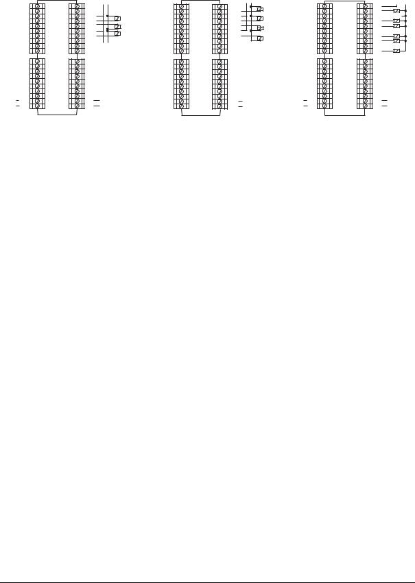
Fig. 3.2: The terminals of the TAC Xenta 281, 282, and 283
Inputs
All TAC Xenta 280 controllers have digital inputs (X).
The TAC Xenta 281 and 282 have universal (analog or digital, U) inputs. The universal inputs can be used for three types of signals:
•TAC thermistor 1.8 kohm at 25 °C (the same as the thermistor inputs)
•Voltage input 0–10V
•open/closed contact (the same as the digital inputs).
The TAC Xenta 282 also has thermistor inputs (labeled B) for 1.8 kohm.
The TAC Xenta 283 has thermistor inputs (labelled B) that can be used with either 1.8 kohm or 10 kohm thermistors.
All controller inputs are protected from transients, in compliance with the EN 50082-1 norm.
Outputs
The TAC Xenta 281 and 282 have the following outputs;
•Analog (Y) — 0–10V DC outputs
•Digital (K) — relay potential-free outputs
While the TAC Xenta 283 has TRIAC (V) — outputs capable of supplying inductive loads.
3.1.2Jacks
The TAC Xenta 280 has two modular jacks–one for the TAC Xenta OP operator panel and one for an RS232 connection with TAC Menta.
The socket for the operator panel provides it with 24V AC or DC, depending on the supply.
18 (74) |
Schneider Electric Buildings AB, June 2011 |
|
04-00067-02-en |

TAC Xenta, TAC Xenta 280/300/401 |
3 Technical Description |
|
|
At distances greater than 10 m (32 ft.) between the TAC Xenta controller and the OP, an external power supply should be used. In addition, the communications connection has to follow the same rules as for other nodes.
Jack for the |
Jack for the |
RS232/modem |
Operator panel |
Fig. 3.3: Location of jacks on the TAC Xenta 280 controller
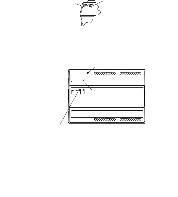
3.1.3LED Indicators and Service pin
The Service pin can be activated through a small hole on the front. Also on the front, there are two LED indicators–one red and one green.
Service pin
Red service diode indicates a non-configured node or a hardware fault
Green status diode indicates that the program is running
Fig. 3.4: LED Indicators and Service Pin
The red service diode is primarily an error indication. It also lights up if the Service pin is activated.
The green status diode blinks once per second to indicate that the program is running.
Schneider Electric Buildings AB, June 2011 |
19 (74) |
04-00067-02-en |
|

3 Technical Description |
TAC Xenta, TAC Xenta 280/300/401 |
|
|
3.1.4Technical Data TAC Xenta 280
Note
•For a complete list of updated technical data for the Xenta 280 controller, see the TAC Xenta 280 Programmable Controller datasheet (003-2248).
Program cycle time |
min. 1 s |
Universal inputs (TAC Xenta 281, 282: U1–U4): |
|
A/D-resolution |
12 bits |
–as Thermistor Inputs |
|
Supply voltage |
0.6V DC |
Thermistor inputs (B1–B2, only TAC Xenta 282): |
|
A/D-resolution |
12 bits |
Accuracy (Measuring range): |
|
–50 °C to –30 °C (–58 °F to –22 °F) |
±4 °C (±7.2 °F) |
–30 °C to –10 °C (–22 °F to +14 °F) |
±2 °C (±3.6 °F) |
–10 °C to +10 °C (14 °F to 50 °F) |
±1 °C (±1.8 °F) |
+10 °C to +30 °C (50 °F to 86 °F) |
±0.5 °C (±0.9 °F) |
+30 °C to +60 °C (86 °F to 140 °F) |
±1 °C (±1.8 °F) |
+60 °C to +120 °C (140 °F to 248 °F) |
±2 °C (±3.6 °F) |
+120 °C to +150 °C (248 °F to 302 °F) |
±4 °C (±7.2 °F) |
Thermistor inputs (B1–B4, only TAC Xenta 283): |
|
A/D-resolution |
10 bits |
Accuracy (Measuring range): |
|
–20 °C to –10 °C (–4 °F to +14 °F) |
±2 °C (±3.6 °F) |
–10 °C to +10 °C (14 °F to 50 °F) |
±1 °C (±1.8 °F) |
+10 °C to +30 °C (50 °F to 86 °F) |
±0,5 °C (±0.9 °F |
+30 °C to +60 °C (86 °F to 140 °F) |
±1 °C (±1.8 °F) |
+60 °C to +90 °C (140 °F to 194 °F) |
±2 °C (±3.6 °F) |
+90 °C to +120 °C (194 °F to 248 °F) |
±4 °C (±7.2 °F |
TRIAC outputs (TAC Xenta 283 only, V1–V6)a: |
|
Load may require auxiliary power |
|
(term. 40) of up to |
72 VA |
Pulse length (TAC Menta DOPU |
|
block) |
min. 0.5 s |
Analog outputs (TAC Xenta 281: Y1–Y3, TAC Xenta 282: Y1–
Y4):
D/A-resolution 12 bits
20 (74) |
Schneider Electric Buildings AB, June 2011 |
|
04-00067-02-en |
TAC Xenta, TAC Xenta 280/300/401 |
3 Technical Description |
|
|
a.If the active sensor (0–10V), analog actuators and the TAC Xenta controller itself are supplied by the same transformer, the following restrictions will ensure the specified accuracy (for thermistor inputs, universal inputs, and analog outputs):
Cable length from controller to: Transformer: 3 m (10 ft.)
Active sensor/actuator: 20 m (65 ft.) Number of active sensors: max. 4 Number of actuators: max.6
Network communication (C1–C2, polarity insensitive):
Protocol |
FTT-10, LONTALK® |
Communication speed |
78 kbits/s |
|
|
Other communication: |
|
|
|
TAC Menta |
RS232, up to 9600 bits/ |
|
s, RJ45 |
TAC Vista (version IV or higher required), also for appl.pgm download
TP/FT-10, screw term.
TAC Xenta OP |
TP/FT-10, modular |
|
jack |
3.2The TAC Xenta 300 Controller.
Fig. 3.5: The TAC Xenta 300 controller
3.2.1Terminals
TAC Xenta 301 and 302
TAC Xenta 300 has two I/O configurations: TAC Xenta 301 and TAC
Xenta 302.
|
Digital |
Thermistor |
Universal |
Relay |
Analog |
|
inputs |
inputs |
inputs |
outputs |
outputs |
|
|
|
|
|
|
Term. notation |
X |
B |
U |
K |
Y |
|
|
|
|
|
|
Schneider Electric Buildings AB, June 2011 |
21 (74) |
04-00067-02-en |
|

3 Technical Description TAC Xenta, TAC Xenta 280/300/401
|
|
|
|
Digital |
Thermistor |
Universal |
Relay |
|
Analog |
|||||
|
|
|
|
inputs |
|
inputs |
inputs |
|
outputs |
|
outputs |
|||
|
TAC Xenta 301 |
|
4 |
|
4 |
|
4 |
|
6 |
|
|
2 |
||
|
TAC Xenta 302 |
|
4 |
|
4 |
|
4 |
|
4 |
|
|
4 |
||
|
|
|
|
max 230 V AC |
|
|
|
|
|
max 230 V AC |
||||
|
|
|
|
|
|
|
|
|
|
|
|
|||
|
X4 |
20 |
40 |
|
|
|
|
|
X4 |
20 |
40 |
|
|
|
|
M |
19 |
39 |
K4 |
|
|
|
|
M |
19 |
39 |
K4 |
|
|
|
X3 |
18 |
38 |
KC2 |
|
|
|
|
X3 |
18 |
38 |
KC2 |
|
|
|
X2 |
17 |
37 |
K3 |
|
|
|
|
X2 |
17 |
37 |
K3 |
|
|
|
M |
16 |
36 |
K2 |
|
|
|
|
M |
16 |
36 |
K2 |
|
|
|
X1 |
15 |
35 |
KC1 |
|
|
|
|
X1 |
15 |
35 |
KC1 |
|
|
|
B4 |
14 |
34 |
K1 |
|
|
|
|
B4 |
14 |
34 |
K1 |
|
|
|
M |
13 |
33 |
K6 |
|
|
|
|
M |
13 |
33 |
|
|
|
|
B3 |
12 |
32 |
KC3 |
|
|
|
|
B3 |
12 |
32 |
|
|
|
|
B2 |
11 |
31 |
K5 |
|
|
|
|
B2 |
11 |
31 |
|
|
|
|
M |
10 |
30 |
|
|
|
|
|
M |
10 |
30 |
|
|
|
|
B1 |
9 |
29 |
|
|
|
|
|
B1 |
9 |
29 |
|
|
|
|
U4 |
8 |
28 |
|
|
|
|
|
U4 |
8 |
28 |
Y4 |
|
|
|
M |
7 |
27 |
|
|
|
|
|
M |
7 |
27 |
M |
|
|
|
U3 |
6 |
26 |
|
|
|
|
|
U3 |
6 |
26 |
Y3 |
|
|
|
U2 |
5 |
25 |
Y2 |
|
|
|
|
U2 |
5 |
25 |
Y2 |
|
|
|
M |
4 |
24 |
M |
|
|
|
|
M |
4 |
24 |
M |
|
|
Comm{ |
U1 |
3 |
23 |
Y1 |
0 |
24 V AC or |
|
Comm{ |
U1 |
3 |
23 |
Y1 |
0 |
|
C2 |
2 |
22 |
G0 |
|
C2 |
2 |
22 |
G0 |
24 V AC or |
|||||
C1 |
1 |
21 |
G |
~ } |
19-40 V DC |
|
C1 |
1 |
21 |
G |
~ |
} 19-40 V DC |
||
|
|
TAC Xenta 301 |
|
|
|
|
|
|
TAC Xenta 302 |
|
|
|
||
Fig. 3.6: The terminals of the TAC Xenta 301 and 302
Inputs
The TAC Xenta 300 controllers have twelve inputs:
•Four thermistor inputs (labeled B1–B4)
•Four universal (analog or digital, U1–U4)
•Four digital (X1–X4).
The universal inputs can be used for three types of signals:
•TAC thermistor 1.8 kohm at 25 °C (the same as the thermistor inputs)
•Voltage input 0–10V
•Open/closed contact (the same as the digital inputs)
All controller inputs are protected from transients, in compliance with the EN 50082-1 norm.
Outputs
The TAC Xenta 300 controllers have eight outputs:
•Analog — 0–10V DC outputs
•Digital — relay potential-free outputs
22 (74) |
Schneider Electric Buildings AB, June 2011 |
|
04-00067-02-en |
TAC Xenta, TAC Xenta 280/300/401 |
3 Technical Description |
|
|
3.2.2Jacks
The TAC Xenta 300 has two modular jacks–one for the TAC Xenta OP operator panel and one for an RS232 connection with TAC Menta.
The socket for the operator panel provides it with 24V AC or DC, depending on the supply.
At distances greater than 10 m (32 ft.) between the TAC Xenta controller and the OP, an external power supply should be used. In addition, the communications connection has to follow the same rules as for other nodes.
Jack for the |
Jack for the |
RS232/modem |
Operator panel |
Fig. 3.7: Location of jacks on the TAC Xenta 280 controller
3.2.3LED Indicators and Service pin
The Service pin can be activated through a small hole on the front. Also on the front are two LED indicators–one red and one green.
Service pin
Red service diode indicates a non-configured node or a hardware fault
Green status diode indicates that the program is running
Fig. 3.8: LED Indicators and Service Pin
The red service diode is primarily an error indication. It also lights up if the Service pin is activated.
The green status diode blinks once per second to indicate that the program is running.
Schneider Electric Buildings AB, June 2011 |
23 (74) |
04-00067-02-en |
|
 Loading...