


OPERATOR’S MANUAL
5 in. Flooring saw
MANUEL D’UTILISATION
SCIE À plancher de 127 mm (5 po) 
MANUAL DEL OPERADOR
SIERRA para pisos de 127 mm (5 pulg.)
RLS1351
Your flooring saw has been engineered and manufactured to our high standard for dependability, ease of operation, and operator safety. When properly cared for, it will give you years of rugged, trouble-free performance.
 WARNING: To reduce the risk of injury, the user must read and understand the operator’s manual before using this product.
Thank you for purchase.
SAVE THIS MANUAL FOR FUTURE REFERENCE
Cette scie à plancher a été conçue et fabriquée conformément à nos strictes normes de fiabilité, simplicité d’emploi et sécurité d’utilisation. Correctement entretenue, elle vous donnera des années de fonctionnement robuste et sans problème.
 AVERTISSEMENT : Pour réduire les risques de blessures, l’utilisateur doit lire et veiller à bien comprendre le manuel d’utilisation avant d’employer ce produit.
Merci de votre achat.
Su sierra para pisos ha sido diseñado y fabricado de conformidad con nuestras estrictas normas para brindar fiabilidad, facilidad de uso y seguridad para el operador. Con el debido cuidado, le brindará muchos años de sólido y eficiente funcionamiento.
 ADVERTENCIA: Para reducir el riesgo de lesiones, el usuario debe leer y comprender el manual del operador antes de usar este producto.
Le agradecemos su compra.
CONSERVER CE MANUEL POUR |
GUARDE ESTE MANUAL PARA |
FUTURE RÉFÉRENCE |
FUTURAS CONSULTAS |

|
TABLE OF CONTENTS |
Introduction...................................................................................................................................................................... |
2 |
Warranty........................................................................................................................................................................... |
2 |
General Safety Rules..................................................................................................................................................... |
3-4 |
Specific Safety Rules....................................................................................................................................................... |
5 |
Symbols........................................................................................................................................................................... |
6 |
Electrical........................................................................................................................................................................... |
7 |
Glossary of Terms............................................................................................................................................................. |
8 |
Features............................................................................................................................................................................ |
9 |
Assembly................................................................................................................................................................... |
10-12 |
Operation................................................................................................................................................................... |
13-15 |
Maintenance................................................................................................................................................................... |
16 |
Accessories.................................................................................................................................................................... |
16 |
Figure Numbers (Illustrations).................................................................................................................................... |
17-22 |
Parts Ordering / Service.................................................................................................................................... |
Back page |
|
INTRODUCTION |
This tool has many features for making its use more pleasant and enjoyable. Safety, performance, and dependability have been given top priority in the design of this product making it easy to maintain and operate.
warranty
RYOBI® POWER TOOL - LIMITED TWO YEAR WARRANTY AND 30 DAY EXCHANGE POLICY
One World Technologies, Inc., warrants its RYOBI® power tools with the following conditions:
30-DAY EXCHANGE POLICY: During the first 30 days after date of purchase, you may either request service under this warranty or you may exchange any RYOBI® power tool which does not work properly due to defective workmanship or materials by returning the power tool to the dealer from which it was purchased. To receive a replacement power tool or requested warranty service, you must present proof of purchase and return all original equipment packaged with the original product. The replacement power tool will be covered by the limited warranty for the balance of the two year period from the date of the original purchase.
WHAT THIS WARRANTY COVERS: This warranty covers all defects in workmanship or materials in your RYOBI® power tool for a period of two years from the date of purchase. With the exception of batteries, power tool accessories are warranted for ninety (90) days. Batteries are warranted for two years.
HOW TO GET SERVICE: Just return the power tool, properly packaged and postage prepaid, to an Authorized Service Center. You can obtain the location of the Service Center nearest you by contacting a service representative at One World Technologies, Inc., P.O. Box 1207, Anderson, SC 29622-1207, by calling 1-800-525-2579 or by logging on to www.ryobitools.com. When you request warranty service, you must also present proof of purchase documentation, which includes the date of purchase (for example, a bill of sale). We will repair any faulty workmanship, and either repair or replace any defective part, at our option. We will do so without any charge to you. We will complete the work in a reasonable time, but, in any case, within ninety (90) days or less.
WHAT’S NOT COVERED: This warranty applies only to the original purchaser at retail and may not be transferred. This warranty only covers defects arising under normal usage and does not cover any malfunction, failure or defects resulting from misuse, abuse, neglect, alteration, modification or repairs by other than Authorized Service Centers. One World Technologies, Inc. makes no warranties, representations or promises as to the quality or performance of its power tools other than those specifically stated in this warranty.
ADDITIONAL LIMITATIONS: Any implied warranties granted under state law, including warranties of merchantability or fitness for a particular purpose, are limited to two years from the date of purchase. One World Technologies, Inc. is not responsible for direct, indirect, or incidental damages, so the above limitations and exclusions may not apply to you. This warranty gives you specific legal rights, and you may also have other rights which vary from state to state.
2

GENERAL SAFETY RULES
WARNING:
Read and understand all instructions. Failure to follow all instructions listed below, may result in electric shock, fire and/or serious personal injury.
READ ALL INSTRUCTIONS
KNOWYOURPOWERTOOL.Readtheoperator’smanual carefully. Learn the applications and limitations as well as the specific potential hazards related to this tool.
GUARD AGAINST ELECTRICAL SHOCKby preventing body contact with grounded surfaces.
For example: pipes, radiators, ranges, refrigerator enclosures.
KEEP GUARDS IN PLACE and in good working order.
REMOVE ADJUSTING KEYS AND WRENCHES. Form habit of checking to see that keys and adjusting wrenches are removed from tool before turning it on.
KEEPWORKAREACLEAN.Clutteredareasandbenches invite accidents. DO NOT leave tools or pieces of wood on the tool while it is in operation.
DO NOT USE IN DANGEROUS ENVIRONMENTS. Do not use power tools in damp or wet locations or expose to rain. Keep the work area well lit.
KEEP CHILDREN AND VISITORS AWAY. All visitors should wear safety glasses and be kept a safe distance from work area. Do not let visitors contact tool or extension cord while operating.
MAKE WORKSHOP CHILDPROOF with padlocks, master switches, or by removing starter keys.
DON’T FORCE THE TOOL. It will do the job better and safer at the feed rate for which it was designed.
USE THE RIGHT TOOL. Do not force the tool or attachment to do a job for which it was not designed.
USE THE PROPER Extension Cord. Make sure your extension cord is in good condition. Use only a cord heavy enough to carry the current your product will draw. An undersized cord will cause a drop in line voltage resulting in loss of power and overheating. A wire gauge size (A.W.G.) of at least 14 is recommended for an extension cord 25 feet or less in length. If in doubt, use the next heavier gauge. The smaller the gauge number, the heavier the cord.
DRESS PROPERLY. Do not wear loose clothing, neckties, or jewelry that can get caught and draw you into moving parts. Rubber gloves and nonskid footwear are recommended when working outdoors. Also wear protective hair covering to contain long hair.
ALWAYS WEAR SAFETY GLASSES WITH SIDE SHIELDS. Everyday eyeglasses have only impactresistant lenses, they are not safety glasses.
SECURE WORK. Use clamps or a vise to hold work when practical, it is safer than using your hand and frees both hands to operate the tool.
DO NOT OVERREACH. Keep proper footing and balance at all times.
MAINTAIN TOOLS WITH CARE. Keep tools sharp and clean for better and safer performance. Follow instructions for lubricating and changing accessories.
DISCONNECT TOOLS. When not in use, before servicing, or when changing attachments, blades, bits, cutters, etc., all tools should be disconnected from power source.
AVOID ACCIDENTAL STARTING. Be sure switch is off when plugging in any tool.
USE RECOMMENDED ACCESSORIES. Consult the operator’s manual for recommended accessories. The use of improper accessories may result in injury.
NEVER STAND ON TOOL. Serious injury could occur if the tool is tipped.
CHECK DAMAGED PARTS. Before further use of the tool, a guard or other part that is damaged should be carefully checked to determine that it will operate properly and perform its intended function. Check for alignment of moving parts, binding of moving parts, breakage of parts, mounting and any other conditions that may affect its operation. A guard or other part that is damaged must be properly repaired or replaced by an authorized service center to avoid risk of personal injury.
USE THE RIGHT DIRECTION OF FEED. Feed work into a blade or cutter against the direction of rotation of the blade or cutter.
NEVER LEAVE TOOL RUNNING UNATTENDED. TURN THE POWER OFF. Don't leave tool until it comes to a complete stop.
PROTECT YOUR LUNGS. Wear a face or dust mask if the cutting operation is dusty.
PROTECT YOUR HEARING. Wear hearing protection during extended periods of operation.
DO NOT ABUSE CORD. Never carry tool by the cord or yank it to disconnect from receptacle. Keep cord from heat, oil, and sharp edges.
USE OUTDOOR EXTENSION CORDS. When tool is used outdoors, use only extension cords with approved ground connection that are intended for use outdoors and so marked.
KEEP BLADES CLEAN, SHARP, and with sufficient set. Sharp blades minimize stalling and kickback.
Blade coasts after being turned off.
3

GENERAL SAFETY RULES
NEVER USE IN AN EXPLOSIVE ATMOSPHERE.
Normal sparking of the motor could ignite fumes.
Inspect TOOL CORDS periodically. If damaged,haverepairedbyaqualifiedservicetechnicianat an authorized service facility. Repair or replace a damaged or worn cord immediately. Stay constantly aware of cord location and keep it well away from the rotating blade.
Inspect EXTENSION CORDS periodically and replace if damaged.
POLARIZED PLUGS. To reduce the risk of electric shock, this tool has a polarized plug (one blade is wider than the other). This plug will fit in a polarized outlet only one way. If the plug does not fit fully in the outlet, reverse the plug. If it still does not fit, contact a qualified electrician to install the proper outlet. Do not change the plug in any way.
Keep TOOL dry, clean, and free from oil and grease. Always use a clean cloth when cleaning. Never use brake fluids, gasoline, petroleum-based products, or any solvents to clean tool.
STAY ALERT AND EXERCISE CONTROL. Watch what you are doing and use common sense. Do not operate tool when you are tired. Do not rush.
DO NOT USE TOOL IF SWITCH DOES NOT TURN IT ON AND OFF. Have defective switches replaced by an authorized service center.
USE ONLY CORRECT BLADES. Do not use blades with incorrect size holes. Never use blade washers or blade bolts that are defective or incorrect. The maximum blade capacity of your saw is 5 in.
Before making a cut, be sure all adjustments are secure.
BE SURE BLADE PATH IS FREE OF NAILS. Inspect for and remove all nails from lumber before cutting.
Never touch blade or other moving parts during use.
NEVER START A TOOL WHEN ANY ROTATiNG COMPONENT IS IN CONTACT WITH THE WORKPIECE.
DO NOT operate A tool while under the influence of drugs, alcohol, or any medication.
When servicing use only identical replacement parts. Use of any other parts may create a hazard or cause product damage.
Use only recommended accessories listed in this manual or addendums. Use of accessories that are not listed may cause the risk of personal injury. Instructions for safe use of accessories are included with the accessory.
DOUBLE CHECK ALL SETUPS. Make sure blade is tight and not making contact with saw or workpiece before connecting to power supply.
4

SPECIFIC SAFETY RULES
KEEP HANDS AWAY FROM CUTTING AREA. Do not reach underneath work or in blade cutting path with hands and fingers for any reason. Always turn the power off.
Always SUPPORT LONG WORKPIECES while cutting to minimize risk of blade pinching and kickback. Saw may slip, walk or slide while cutting long or heavy boards.
Always use the work clamp to secure the workpiece when making cross cuts.
BE SURE THE BLADE CLEARS THE WORKPIECE.
Never start the saw with the blade touching the workpiece. Allow motor to come up to full speed before starting cut.
NEVER cut more than one piece at a time. Do not stack more than one workpiece on the saw table at a time.
NEVER perform any operation freehand.
Always place the workpiece to be cut on the saw table and position it firmly against the fence as a backstop. Always use the fence.
Never hand hold a workpiece that is too small to be clamped. Keep hands clear of the cutting area.
NEVER reach behind, under, or within three inches of the blade and its cutting path with hands and fingers for any reason.
NEVER reach to pick up a workpiece, a piece of scrap, or anything else that is in or near the cutting path of the blade.
NEVER move the workpiece or make adjustment to any cutting angle while the saw is running and the blade is rotating. Any slip can result in contact with the blade causing serious personal injury.
AVOID AWKWARD OPERATIONS AND HAND POSITIONS where a sudden slip could cause your hand to move into the blade. Always make sure you have good balance.
NEVER stand or have any part of the body in line with the path of the saw blade.
ALWAYSreleasethepowerswitchandallowthesawblade to stop rotating before raising it out of the workpiece.
Do not turn the motor switch on and off rapidly. This could cause the saw blade to loosen and could create a hazard. Should this ever occur, stand clear and allow the saw blade to come to a complete stop. Disconnect your saw from the power supply and securely retighten the blade bolt.
If any part of this saw is missing or should break, bend, or fail in any way, or should any electrical component fail to perform properly, shut off the power switch, remove the saw plug from the power source and have damaged, missing, or failed parts replaced before resuming operation.
Always stay alert! Do not allow familiarity (gained from frequent use of the saw) to cause a careless mistake. ALWAYS REMEMBER that a careless frac-
tion of a second is sufficient to inflict severe injury.
IF THE POWER SUPPLY CORD IS DAMAGED, it must be replaced only by the manufacturer or by an authorized service center to avoid risk.
make sure work area has ample lighting to see the work and that no obstructions will interfere with safe operation BEFORE performing any work using the saw.
ALWAYS TURN OFF THE SAW before disconnecting it to avoid accidental starting when reconnecting to power supply. NEVERleave the saw unattended while connected to a power source.
turn the saw off. Wait for the blade to come to a complete stop before removing the workpiece.
THIS TOOL should have the following markings:
a)Wear eye protection.
b)Keep hands and body out of path of saw blade.
c)Do not operate saw without guards in place.
d)Do not perform any operation freehand.
e)Never reach around or over saw blade.
f)Turn off tool and wait for saw blade to stop before moving workpiece or changing settings.
g)Disconnect power (or unplug tool as applicable) before changing blade or servicing.
h)Return saw to rear of tool after each cross cut.
i)Use a push stick for narrow work and when required.
j)Pay particular attention to instruction on reducing risk of kickback.
ALWAYS MAKE SURE THE SAW BLADE HAS CLEARANCE OF ALL OBSTRUCTIONS BEFORE TURNING THE SAW ON.
ALWAYS carry the tool only by the carrying handle.
SAVE THESE INSTRUCTIONS. Refer to them frequently and use to instruct other users. If you loan someone this tool, loan them these instructions also.
5
SYMBOLS
The following signal words and meanings are intended to explain the levels of risk associated with this product.
SYMBOL |
SIGNAL |
MEANING |
|
|
|
|
DANGER: |
Indicates an imminently hazardous situation, which, if not avoided, will result |
|
in death or serious injury. |
|
|
|
|
|
|
|
|
WARNING: |
Indicates a potentially hazardous situation, which, if not avoided, could result |
|
in death or serious injury. |
|
|
|
|
|
|
|
|
CAUTION: |
Indicates a potentially hazardous situation, which, if not avoided, may result in |
|
minor or moderate injury. |
|
|
|
|
|
|
|
|
CAUTION: |
(Without Safety Alert Symbol) Indicates a situation that may result in property |
|
damage. |
|
|
|
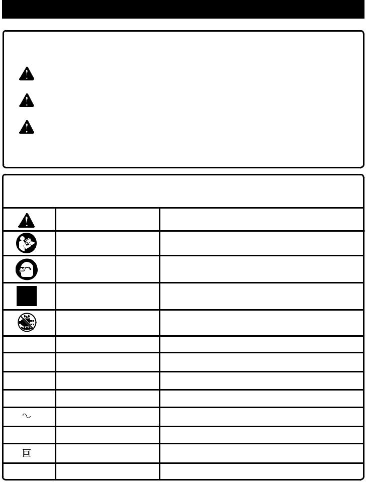
Some of the following symbols may be used on this tool. Please study them and learn their meaning. Proper interpretation of these symbols will allow you to operate the tool better and safer.
SYMBOL |
NAME |
DESIGNATION/EXPLANATION |
|
Safety Alert |
Precautions that involve your safety. |
|
Read Operator’s Manual |
To reduce the risk of injury, user must read and understand opera- |
|
tor’s manual before using this product. |
|
|
|
|
|
Eye Protection |
Always wear eye protection with side shields marked to comply |
|
with ANSI Z87.1. |
|
|
|
|
|
No Hands Symbol |
Failure to keep your hands away from the blade will result in |
|
serious personal injury. |
|
|
|
|
|
Wet Conditions Alert |
Do not expose to rain or use in damp locations. |
V |
Volts |
Voltage |
A |
Amperes |
Current |
Hz |
Hertz |
Frequency (cycles per second) |
min |
Minutes |
Time |
|
Alternating Current |
Type of current |
no |
No Load Speed |
Rotational speed, at no load |
|
Class II Construction |
Double-insulated construction |
.../min |
Per Minute |
Revolutions, strokes, surface speed, orbits etc., per minute |
6

ELECTRICAL
DOUBLE INSULATION
Double insulation is a concept in safety in electric power tools, which eliminates the need for the usual threewire grounded power cord. All exposed metal parts are isolated from the internal metal motor components with protecting insulation. Double insulated tools do not need to be grounded.
WARNING:
The double insulated system is intended to protect the user from shock resulting from a break in the tool’s internal insulation. Observe all normal safety precautions to avoid electrical shock.
NOTE: Servicing of a tool with double insulation requires extreme care and knowledge of the system and should be performed only by a qualified service technician. For service, we suggest you return the tool to the nearest authorized service center for repair. Always use original factory replacement parts when servicing.
ELECTRICAL CONNECTION
This tool has a precision-built electric motor. It should be connected to a power supply that is 120 volts, AC only (normal household current), 60 Hz. Do not operate this tool on direct current (DC). A substantial voltage drop will cause a loss of power and the motor will overheat. If the tool does not operate when plugged into an outlet, double-check the power supply.
EXTENSION CORDS
When using a power tool at a considerable distance from a power source, be sure to use an extension cord that has the capacity to handle the current the tool will draw. An undersized cord will cause a drop in line voltage, resulting in overheating and loss of power. Use the chart to determine the minimum wire size required in an extension cord. Only round jacketed cords listed by Underwriter’s Laboratories (UL) should be used.
When working outdoors with a tool, use an extension cord that is designed for outside use. This type of cord is designated with “WA” on the cord’s jacket.
Before using any extension cord, inspect it for loose or exposed wires and cut or worn insulation.
**Ampere rating (on tool data plate) |
|
|
|
|||
|
0-2.0 2.1-3.4 |
3.5-5.0 5.1-7.0 7.1-12.0 |
12.1-16.0 |
|||
|
|
|
|
|
||
Cord Length |
|
Wire Size (A.W.G.) |
|
|
||
|
|
|
|
|
|
|
25' |
16 |
16 |
16 |
16 |
14 |
14 |
|
|
|
|
|
|
|
50' |
16 |
16 |
16 |
14 |
14 |
12 |
100' |
16 |
16 |
14 |
12 |
10 |
— |
**Used on 12 gauge - 20 amp circuit.
NOTE: AWG = American Wire Gauge
WARNING:
Keep the extension cord clear of the working area. Position the cord so that it will not get caught on lumber, tools or other obstructions while you are working with a power tool. Failure to do so can result in serious personal injury.
WARNING:
Check extension cords before each use. If damaged replace immediately. Never use tool with a damaged cord since touching the damaged area could cause electrical shock resulting in serious injury.
7

GLOSSARY OF TERMS
Anti-Kickback Pawls (flooring, radial arm, and table saws)
A device which, when properly installed and maintained, is designed to stop the workpiece from being kicked back toward the front of the saw during a ripping operation.
Arbor
The shaft on which a blade or cutting tool is mounted.
Bevel Cut
A cutting operation made with the blade at any angle other than 90° to the table surface.
Compound Cut
A cross cut made with both a miter and a bevel angle.
Cross Cut
A cutting or shaping operation made across the grain or the width of the workpiece.
Cutterhead (planers and jointer planers)
A rotating cutterhead with adjustable blades or knives. The blades or knives remove material from the workpiece.
Dado Cut
A non-through cut which produces a square-sided notch or trough in the workpiece (requires a special blade).
Featherboard
A device used to help control the workpiece by holding it securely against the table or fence during any ripping operation.
FPM or SPM
Feet per minute (or strokes per minute), used in reference to blade movement.
Freehand
Performing a cut without the workpiece being guided by a fence, miter gauge, or other aids.
Gum
A sticky, sap-based residue from wood products.
Heel
Alignment of the blade to the fence.
Kerf
The material removed by the blade in a through cut or the slot produced by the blade in a non-through or partial cut.
Kickback
A hazard that can occur when the blade binds or stalls, throwing the workpiece back toward operator.
Miter Cut
A cutting operation made with the workpiece at any angle to the blade other than 90°.
Non-Through Cuts
Any cutting operation where the blade does not extend completely through the thickness of the workpiece.
Pilot Hole (drill presses)
A small hole drilled in a workpiece that serves as a guide for drilling large holes accurately.
Push Blocks (jointer planers)
Device used to feed the workpiece over the jointer planer cutterhead during any operation. This aid helps keep the operator’s hands well away from the cutterhead.
Push Blocks (flooring and table saws)
Device used to hold the workpiece during cutting operations. This aid helps keep the operator’s hands well away from the blade.
Push Sticks (flooring and table saws)
Device used to push the workpiece during cutting operations. A push stick should be used for narrow ripping operations. The aid helps keep the operator’s hands well away from the blade.
Resaw
A cutting operation to reduce the thickness of the workpiece to make thinner pieces.
Resin
A sticky, sap-based substance that has hardened.
Revolutions Per Minute (RPM)
The number of turns completed by a spinning object in one minute.
Ripping or Rip Cut
A cutting operation along the length of the workpiece.
Riving Knife/Spreader/Splitter (flooring and table saws)
A metal piece, slightly thinner than the blade, which helps keep the kerf open and also helps to prevent kickback.
Saw Blade Path
The area over, under, behind, or in front of the blade. As it applies to the workpiece, that area which will be or has been cut by the blade.
Set
The distance that the tip of the saw blade tooth is bent (or set) outward from the face of the blade.
Snipe (planers)
Depression made at either end of a workpiece by cutter blades when the workpiece is not properly supported.
Through Sawing
Any cutting operation where the blade extends completely through the thickness of the workpiece.
Throw-Back
The throwing back of a workpiece usually caused by the workpiece being dropped into the blade or being placed inadvertently in contact with the blade.
Workpiece or Material
The item on which the operation is being done.
Worktable
Surface where the workpiece rests while performing a cutting, drilling, planing, or sanding operation.
8

FEATURES
PRODUCT SPECIFICATIONS
Blade Diameter. |
............................................................5 in. |
Blade Arbor............................................................... |
5/8 in. |
Rip Capacity.................................................................. |
8 in. |
Miter Capacity............................................................. |
11 in. |
Input................................................ |
120 V~, 60 Hz, 7 Amps |
No Load Speed.................................... |
11,000 r/min. (RPM) |
KNOW YOUR flooring saw
See Figure 1, page 17.
The safe use of this product requires an understanding of the information on the tool and in this operator’s manual as well as a knowledge of the project you are attempting. Before use of this product, familiarize yourself with all operating features and safety rules.
5 in. BLADE - A 5 in. blade is included with the saw. It will cut materials up to 3/4 in. thick.
WARNING:
Do not use blades rated less than the speed of this tool. Failure to heed this warning could result in personal injury.
ANTI-KICKBACK PAWLS (for use with rip cuts) - Kickback is a hazard in which the workpiece is thrown back toward the operator. The teeth on the anti-kickback pawls point away from the workpiece. If the workpiece should be pulled back toward the operator, the teeth dig into the workpiece to help prevent or reduce the possibility of kickback.
BLADE GUARD - Always keep the blade guard down and over the saw blade for all cuts.
BLADE GUARD ADJUSTMENT KNOB - Set the clearance of the workpiece using the blade guard adjustment knob. Clearance between the workpiece and blade guard should be set between 1/16 in. - 3/32 in.
BLADE WRENCH STORAGE - A blade wrench is packed with the saw. One end of the wrench is a phillips screwdriver and the other end is a hex key. Use the hex key end when installing or removing blade and the phillips end when removing or loosening screws. A storage area for the blade wrench is located under the saw’s table.
Carrying Handle - For convenience when carrying or transporting the saw from one place to another, a carrying handle has been provided on the side of the saw.
FENCE - The fence attaches to the saw table and can be angled for miter cuts as well as placed straight for rip cuts. With the locator pin in place, the clamp knob locks the fence to the table at the desired cutting angle.
MITER GROOVE - The attachment bolt rides in the miter groove on the saw table to secure the fence in place when making miter cuts.
ON/OFF SWITCH - This saw has an easy access power switch located on the front of the saw. To lock the switch in the OFF position, remove the switch key from the switch. Place the key in a location that is inaccessible to children and others not qualified to use the tool.
RIP GROOVES - The attachment bolt rides in the rip groove on the saw table to secure the fence in place when making rip cuts.
RIVING KNIFE - A metal piece, slightly thinner than the saw blade which helps keep the kerf open and prevent kickback.
9

ASSEMBLY
LOOSE PARTS LIST |
|
|
See Figure 2, page 17. |
|
|
The following items are included with the saw: |
|
|
Key |
|
|
No. |
Description |
Qty. |
A |
Saw Handle.......................................................... |
1 |
B |
Screws................................................................. |
2 |
C |
Blade Wrench....................................................... |
1 |
D |
Screws................................................................. |
4 |
E |
Feet...................................................................... |
4 |
F |
Push Stick............................................................ |
1 |
G |
Work Clamp.......................................................... |
1 |
H |
Fence................................................................... |
1 |
I |
Dust Bag.............................................................. |
1 |
J |
Screws................................................................. |
2 |
K |
Foot/Blade Wrench Holder................................... |
1 |
|
Operator’s Manual (not shown)............................ |
1 |
UNPACKING
This product requires assembly.
Carefully lift saw from carton and place on a level work surface.
WARNING:
Do not use this product if any parts on the Loose Parts List are already assembled to your product when you unpack it. Parts on this list are not assembled to the product by the manufacturer and require customer installation. Use of a product that may have been improperly assembled could result in serious personal injury.
Inspect the tool carefully to make sure no breakage or damage occurred during shipping.
Do not discard the packing material until you have carefully inspected and satisfactorily operated the product.
The saw is factory set for accurate cutting. After assembling it, check for accuracy. If shipping has influenced the settings, take to an authorized service center.
If any parts are damaged or missing, please call 1-800-525-2579 for assistance.
Warning:
If any parts are damaged or missing do not operate this product until the parts are replaced. Use of this product with damaged or missing parts could result in serious personal injury.
warning:
Do not attempt to modify this product or create accessories not recommended for use with this tool. Any such alteration or modification is misuse and could result in a hazardous condition leading to possible serious personal injury.
WARNING:
Do not connect to power supply until assembly is complete. Failure to comply could result in accidental starting and possible serious personal injury.
WARNING:
Never stand directly in line with the blade or allow hands to come closer than 3 in. to the blade. Do not reach over or across the blade. Failure to heed this warning can
result in serious personal injury.
NOTE: No adjustments that can made to this tool except by an authorized service center.
TO install the saw handle
See Figure 3, page 18.
Position the saw handle over the holes in the saw housing (straight side of the handle to the back).
Secure saw handle in place using Phillips screws.
TO install the Foot/Blade Wrench holder
See Figure 4, page 18.
Align holes in foot/blade wrench holder with holes under the saw base.
Insert Phillips screw through the foot and into the base. Tighten securely.
TO attach saw to mounting boards or work bench
See Figure 5, page 18.
The saw should be mounted to a firm supporting surface such as a workbench or mounting boards. Four bolt holes have been provided in the feet for this purpose. Secure using bolts and washers (not included). Bolts should be of sufficient length to accommodate the saw base, washers, and the thickness of the workbench or mounting board. Tighten bolts securely.
10
ASSEMBLY
TO install the feet to the saw base
See Figure 6, page 18.
Align hole in foot with hole in saw base.
Insert a Phillips screw in the bottom of the foot and into the base. Tighten securely.
Repeat for the other three feet.
to install WORK CLAMP
See Figure 7, page 19.
WARNING:
In some operations, the work clamp assembly may interfere with the operation of the blade guard assembly. Always make sure there is no interference with the blade guard prior to beginning any cutting operation to reduce the risk of serious personal injury.
The work clamp provides greater control by clamping the workpiece to the saw table. Use the work clamp on all nonrip cuts.
To install the work clamp:
Hold the attachment bolt in place while unscrewing and removing the clamp knob.
Place the work clamp over the attachment bolt and secure in place using the clamp knob.
To use the work clamp:
With fence mounted to the saw table (see instructions below), place the workpiece firmly against the fence.
Rotate the knob on the work clamp to move the clamp up or down as needed. Do not overtighten.
TO INSTALL FENCE for making miter / cross cuts
See Figures 7 - 8, page 19.
Install the work clamp to the fence. Do not tighten attachment bolt.
Place the attachment bolt into the miter groove and the locator pin (under right side of fence) in the anchor hole.
Slide the adjusting clamp along the miter groove until reaching the desired angle.
Tighten the clamp knob securely.
TO INSTALL FENCE for making rip cuts
See Figure 9, page 19.
Remove the work clamp from the fence. Do not tighten attachment bolt.
Place the attachment bolt into the rip groove.
With the fence parallel to the saw table, place the locator pin in the right groove of the saw table and the left side of the fence in the left groove of the saw table.
Slide the adjusting clamp along the rip groove until reaching the desired distance for the cut.
Using the scales on the saw table, check that both the left and right sides of the fence are the same distance from the blade so the fence is squared to the blade.
NOTE: If you cannot square the fence to the blade, contact an authorized service center for assistance.
Tighten the clamp knob securely.
TO use the DUST BAG
See Figure 10, page 19.
Slide dust bag onto dust exhaust port.
WARNING:
Collected dust from surface coatings such as polyurethanes, linseed oil, etc., can self-ignite in the dust bag or elsewhere and cause fire. To reduce the risk of fire, always empty the dust bag frequently (10-15 minutes) and never store or leave the tool without totally emptying its dust bag. Also follow the recommendations of the coatings manufacturers.
TO USE WITH A VACUUM
You can easily attach a vacuum to the saw.
To attach:
Remove dust bag from saw.
Attach vacuum hose to dust exhaust port.
WARNING:
When not connected to vacuum, always install the dust bag back on saw. Failure to do so could cause dust or foreign objects to be thrown into the face or eyes which could result in possible serious injury.
11

ASSEMBLY
To Install / replace the Blade
See Figures 11 - 12, pages 19 - 20.
WARNING:
A 5 in. blade is the maximum blade capacity of the saw. Never use a blade that is too thick. Larger blades will come in contact with the blade guard, while thicker blades will prevent the blade bolt from securing the blade. Either of these situations could result in a serious accident and can cause serious personal injury.
NOTE: The saw blade is removed from beneath the saw base by passing the blade through the throat plate. If the saw is mounted to a work bench, it will be necessary to remove the saw to install/replace the blade.
Unplug the saw.
Raise the blade guard by turning the blade guard adjustment knob counterclockwise.
Loosen screw on blade bolt cover.
Rotate blade bolt cover up and back to expose the blade bolt.
Depress the spindle lock button and rotate the blade bolt until the spindle locks.
Using the blade wrench provided, loosen and remove the blade bolt.
Note: The blade bolt has right hand threads. Turn blade bolt counterclockwise to loosen.
Remove the outer blade washer. Do not remove the inner blade washer.
Lift the side legs of the saw and carefully slip the blade through the throat plate removing the blade from under the saw base.
Wipe a drop of oil onto inner blade washer and outer blade washer where they contact the blade.
WARNING:
If the inner blade washer has been removed, replace it before placing blade on saw. Failure to do so could cause an accident since blade will not tighten properly.
Fit saw blade inside blade guard and onto spindle. The blade teeth point upward as shown in figure 12. NOTE: Kerf must be a minimum of 3/32 in.
Replace the outer blade washer. Double “D” flats on blade washers align with flats on spindle.
Depress spindle lock button and replace blade bolt.
Caution:
Always install the blade with the blade teeth and the arrow printed on the side of the blade pointing up at the front of the saw.
Tighten blade bolt securely.
Note: The blade bolt has right hand threads. Turn blade bolt clockwise to tighten.
Replace blade bolt cover and screw.
Tighten screw securely.
Lower the blade guard by turning the blade guard adjustment knob clockwise until the clearance of the blade guard from the saw table is between 1/16 in. -
3/32 in.
to Store accessories
See Figure 13, page 20.
The saw has a convenient storage area specifically designed for the push stick (on the back of the saw table) and the blade wrench (under the saw table).
To store the push stick:
Place the large holes in the key hole slot on the push stick over the screws.
NOTE: Large holes should be on the bottom.
Place the push stick firmly against the saw and push the stick down toward the floor.
NOTE: When stored properly, the push stick will be below the saw table.
To store the blade wrench:
With saw unplugged, tilt the saw table back.
Push the blade wrench into the storage slot on the foot/ blade wrench holder.
to move the saw
See Figure 14, page 20.
When transporting the saw, always lock the saw to prevent the saw arm from moving on the sliding rails.
Unplug the saw.
Push or pull the saw on the sliding rails until the lock pin and hole in the rail are aligned.
Push the lock pin in the hole to lock the saw in place.
Store the cord by wrapping it around the cord wrap.
Lift the saw by the carrying handle to transport.
12

OPERATION
WARNING:
Do not allow familiarity with tools to make you careless. Remember that a careless fraction of a second is sufficient to inflict serious injury.
WARNING:
Always wear eye protection with side shields marked to comply with ANSI Z87.1. Failure to do so could result in objects being thrown into your eyes, resulting in possible serious injury.
WARNING:
Do not use any attachments or accessories not recommended by the manufacturer of this tool. The use of attachments or accessories not recommended can result in serious personal injury.
APPLICATIONS
This product has been designed only for the purpose listed below:
Cutting laminate, engineered, and solid, hardwood flooring material
WARNING:
NEVER make adjustment to any cutting angle while the saw is running and the blade is rotating. Any slip can result in contact with the blade causing serious personal injury.
AVOIDING KICKBACK
Inspect the work for knots or nails before beginning a cut. Knock out any loose knots with a hammer. Never saw into a loose knot or nail.
Always use the fence when rip cutting. This helps prevent twisting the wood in the cut.
Always use clean, sharp, and properly set blades. Never make cuts with dull blades.
To avoid pinching the blade, support the work properly before beginning a cut.
When making a cut, use steady, even pressure. Never force cuts.
Do not cut wet or warped lumber.
Use extra caution when cutting some prefinished or composition wood products as the anti-kickback pawls may not always be effective.
Always guide your workpiece with both hands or with push sticks and/or push blocks. Keep your body in a
balanced position to be ready to resist kickback should it occur. Never stand directly in line with the blade.
Clean the saw, blade guard, under the throat plate, and any areas where saw dust or scrap workpieces may gather.
Use the right type of blade for the cut being made.
Always use the riving knife for every operation where it is allowed. The use of this device will greatly reduce the risk of kickback.
cutting aids
See Figure 15, page 21.
Push sticks are devices that may be used for pushing a workpiece through the blade in any rip cut. When ripping narrow stock, always use a push stick or push block so your hands do not come within 3 inches of the saw blade. They can be made in various sizes and shapes from scrap wood and used in a specific project. The stick must be narrower than the workpiece, with a 90˚ notch in one end and shaping for a grip on the other end.
A push block has a handle fastened by recessed screws from the underside. Use push blocks for narrow cuts and all non-through cuts.
CAUTION:
Be sure the screws in a push block are recessed to avoid damaging the saw or workpiece.
to use on/off switch
See Figure 16, page 21.
This saw is equipped with a switch assembly that has a built-in locking feature. This feature is intended to prevent unauthorized and possible hazardous use by children and others.
TO TURN YOUR SAW ON:
With the switch key inserted into the switch, lift the switch to turn on.
TO TURN YOUR SAW OFF:
Press the switch down to turn off.
TO lock your saw:
Press the switch down.
Remove the switch key from the switch and store in a safe, secure location.
WARNING:
ALWAYS remove the switch key when the tool is not in use and keep it in a safe place. In the event of a power failure, turn the switch off and remove the key. This action will prevent the tool from accidentally starting when power returns.
13

OPERATION
WARNING:
ALWAYS make sure your workpiece is not in contact with the blade before operating the switch to start the tool. Failure to heed this warning may cause the workpiece to be kicked back toward the operator and result in serious personal injury.
Warning:
To reduce the risk of accidental starting, Always make sure the switch is in the off position before plugging tool into the power source.
To use the indicator
See Figure 17, page 21.
The indicator on the front of the blade guard is provided for marking the location of the saw cut (kerf) on the workpiece.
Turn the saw on.
Make a practice cut on scrap material to learn the path of the blade.
Turn the saw off and leave the cut material on the saw table.
Loosen the indicator screw.
Align the saw cut with the indicator by moving the indicator left or right as needed.
Tighten screw securely.
To use the blade guard adjustment knob
See Figure 17, page 21.
Clearance between the workpiece and the bottom of the blade guard should be between 1/16 in. - 3/32 in. Set the clearance by turning the blade guard adjustment knob left or right as needed.
To raise and lower anti-kickback pawls
See Figure 18, page 21.
The anti-kickback pawls are only used for making rip cuts. These pawls are spring-loaded and very sharp. Use only one finger to raise or lower these pawls while carefully keeping all body parts away from the sharp points of the pawls.
To lower the anti-kickback pawls:
From behind the saw, place one finger under the release lever.
Lift up on the release lever and maintain pressure on the lever.
Slowly lower the pawls towards the throat plate. When pawls are completely lowered, move finger from the release lever.
To raise the anti-kickback pawls:
From behind the saw, place one finger under the release lever and lift until the lever touches the bottom of the blade guard. Hold in place.
Push the lock button in.
Remove finger from the release lever while continuing to push the lock button in. When hands are clear of the pawls, release the lever.
Making CUTS
This saw can perform a variety of cuts that are not all mentioned in this manual. DO NOT attempt to make any cuts not covered here unless you are thoroughly familiar with the proper procedures and necessary accessories. Your local library has many books on saw usage and specialized woodworking procedures for your reference.
The blade provided with your saw is a high-quality combination blade suitable for ripping and cross cut operations. Carefully check all setups and rotate the blade one full revolution to assure proper clearance before connecting saw to power source.
WARNING:
Do not use blades rated less than the speed of this tool. Failure to heed this warning could result in personal injury.
14

OPERATION
WARNING:
Always keep hands and body out of the path of the saw blade. Failure to heed this warning could result in personal injury.
to make a Cross cut
See Figure 19, page 22.
A cross cut is made by cutting across the width of the workpiece.
Install the work clamp on the fence.
Place the fence in the cross cut position (see page 11) and set at 0°. Tighten the clamp knob securely.
Pull out the lock pin and push the saw to the rear of the saw table.
Place the workpiece flat on the saw table with one edge securely against the fence.
Align cutting line on the workpiece with the edge of saw blade. Use the work clamp to secure the workpiece. Do not overtighten.
Make sure the wood is clear of the blade before turning on the saw.
Turn the saw on.
Let the blade build up to full speed before feeding the workpiece into the blade.
Grasp the saw handle firmly. Allow several seconds for the blade to reach maximum speed.
Slowly pull the blade into and through the workpiece.
When the cut is made, turn the saw off. Wait for the blade to come to a complete stop before removing the workpiece.
to make a miter cut
See Figure 20, page 22.
Miter cuts are made with the fence set at some angle other than 0°.
Install the work clamp on the fence.
Place the fence in the miter cut position (see page 11) and the fence to the desired angle. Tighten the clamp knob securely.
Pull out the lock pin and push the saw to the rear of the saw table.
Place the workpiece flat on the saw table with one edge securely against the fence.
Align cutting line on the workpiece with the edge of saw blade. Use the work clamp to secure the workpiece. Do not overtighten.
Make sure the wood is clear of the blade before turning on the saw.
Turn the saw on.
Let the blade build up to full speed before feeding the workpiece into the blade.
Grasp the saw handle firmly. Slowly pull the blade into and through the workpiece.
When the cut is made, turn the saw off. Wait for the blade to come to a complete stop before removing the workpiece.
TO make a RIP Cut
See Figures 21 - 22, page 22.
Rip cuts are made with the saw locked in place. If the fence isn’t properly squared to the blade, the cut edges of the workpiece may blacken or scorch.
Remove the work clamp from the fence.
Push or pull the saw on the sliding rails until the lock pin and hole in the rail are aligned.
Push the lock pin in the hole locking the saw in place.
Place the fence in the rip cut position (see page 11) the desired distance from the blade for the cut. Tighten the clamp knob securely.
Lower the anti-kickback pawls (see page 14).
Place the workpiece flat on the saw table with one edge securely against the fence.
Align cutting line on the workpiece with the indicator.
Make sure the wood is clear of the blade before turning on the saw.
When ripping a long workpiece, place a support the same height as the table surface behind the saw for the cut work.
Turn the saw on.
Let the blade build up to full speed before feeding the workpiece into the blade.
Once the blade has made contact with the workpiece, use the hand closest to the fence to guide it. Make sure the edge of the workpiece remains in solid contact with both the fence and the surface of the table. Use a push stick and/or push blocks to move the piece through the cut and past the blade.
When the cut is made, turn the saw off. Wait for the blade to come to a complete stop before removing the workpiece.
15

MAINTENANCE
WARNING:
When servicing, use only identical replacement parts. Use of any other parts may create a hazard or cause product damage.
WARNING:
Always wear eye protection with side shields marked to comply with ANSI Z87.1 during product operation. If operation is dusty, also wear a dust mask.
WARNING:
Before performing any maintenance, make sure the tool is unplugged from the power supply and the switch is in the off position. Failure to heed this warning could result in serious personal injury.
GENERAL MAINTENANCE
Avoid using solvents when cleaning plastic parts. Most plastics are susceptible to damage from various types of commercial solvents and may be damaged by their use. Use clean cloths to remove dirt, dust, oil, grease, etc.
WARNING:
Do not at any time let brake fluids, gasoline, petroleumbased products, penetrating oils, etc., come in contact with plastic parts. Chemicals can damage, weaken, or destroy plastic which may result in serious personal injury.
Periodically check all clamps, nuts, bolts, and screws for tightness and condition. Make sure the throat plate is in good condition and in position.
Check the blade guard.
Clean the fence and rails with a gum and pitch remover.
Clean plastic parts only with a soft damp cloth. DO NOT use any aerosol or petroleum solvents.
LUBRICATION
All of the bearings in this tool are lubricated with a sufficient amount of high grade lubricant for the life of the unit under normal operating conditions.
Some areas will require lubrications. You will need to apply:
Light oil or a pressurized light spray oil to the sliding rails.
To remove / replace the throat plate
See Figure 23, page 22.
WARNING:
The throat plate must be below the saw table. If the throat plate is too high or too low, the workpiece can catch on the uneven edges resulting in binding which could result in serious personal injury.
Never operate the saw without a throat plate installed.
To remove / replace:
Unplug the saw.
Remove the screws securing the throat plate.
Lift the throat plate from the saw. Repeat the above steps for the left side of the throat plate.
To reinstall the throat plate, align the holes in the throat plate with the holes in the saw base.
Retighten the screws, being careful not to overtighten which can cause the throat plate to bow or bend.
ACCESSORIES
The following recommended accessories are currently available at retail stores:
089230100053 Saw Blade
 WARNING:
Current attachments and accessories available for use with this tool are listed above. Do not use any attachments or accessories not recommended by the manufacturer of this tool. The use of attachments or accessories not recommended can result in serious personal injury.
16

|
TABLE DES MATIÈRES |
Introduction...................................................................................................................................................................... |
2 |
Garantie............................................................................................................................................................................ |
2 |
Règles de sécurité générales........................................................................................................................................ |
3-4 |
Règles de sécurité particulières....................................................................................................................................... |
5 |
Symboles......................................................................................................................................................................... |
6 |
Caractéristiques électriques............................................................................................................................................ |
7 |
Glossaire.......................................................................................................................................................................... |
8 |
Caractéristiques............................................................................................................................................................... |
9 |
Assemblage............................................................................................................................................................... |
10-12 |
Utilisation.................................................................................................................................................................. |
13-15 |
Entretien......................................................................................................................................................................... |
16 |
Accessoires.................................................................................................................................................................... |
16 |
Figure numéros (illustrations).................................................................................................................................... |
17-22 |
Commande de pièces / réparation................................................................................................................. |
páge arrière |
|
INTRODUCTION |
Cet outil offre de nombreuses fonctions destinées à rendre son utilisation plaisante et plus satisfaisante. Lors de la conception de ce produit, l’accent a été mis sur la sécurité, les performances et la fiabilité, afin d’en faire un outil facile à utiliser et à entretenir.
GARANTIE
OUTILS ÉLECTRIQUES RYOBI® – GARANTIE LIMITÉE DE DEUX ANS ET POLITIQUE D’ÉCHANGE DE 30 JOURS
One World Technologies, Inc., garantit ses outils électriques dans les conditions suivantes :
POLITIQUE D’ÉCHANGE DE 30 JOURS : En cas de défaillance due à des vices de matériaux ou de fabrication au cours des 30 jours suivant la date d’achat, l’acheteur pourra faire réparer tout outil électrique Ryobi® au titre de cette garantie ou le retourner l’établissement où il a été acheté. Pour obtenir un outil en échange ou demander la réparation en garantie, l’équipement complet devra être retourné, dans son emballage d’origine, accompagné d’une preuve d’achat. L’outil fourni en échange sera couvert par la garantie limitée pour le restant de la période de validité de deux ans à compter de la date d’achat.
CE QUI EST COUVERT PAR LA GARANTIE : Cette garantie couvre tous les vices de matériaux et de fabrication de cet outil électrique Ryobi®, pour une période de deux ans, à compter de la date d’achat. À l’exception des batteries, les accessoires sont garantis pour une période de quatre-vingt-dix (90) jours. Les batteries sont garanties deux ans.
RÉPARATIONS SOUS GARANTIE : Il suffit de retourner l’outil, correctement emballé, en port payé, à un centre de réparations agréé. L’adresse du centre de réparations agréé le plus proche peut être obtenue en contactant un représentant du service après-vente par courrier, à l’adresse One World Technologies, Inc., P.O. Box 1207, Anderson, SC 29622-1207, par téléphone au 1-800-525-2579 ou par courriel, à l’adresse Internet www.ryobitools.com. Lors de toute demande de réparation sous garantie, une preuve d’achat datée (par exemple un reçu de vente) doit être fournie. Nous nous engageons
à réparer tous les défauts de fabrication et à réparer ou remplacer, à notre choix, toutes les pièces défectueuses. Les réparations et remplacements seront gratuits. Les réparations sous garantie seront effectuées dans un délai raisonnable, ne dépassant en aucun cas quatre-vingt-dix (90) jours.
CE QUI N’EST PAS COUVERT : La garantie ne couvre que l’acheteur au détail original et n’est pas transférable. Cette garantie ne couvre que les défauts résultant d’une utilisation normale. Elle ne couvre pas les problèmes de fonctionnement, défaillances ou autres défauts résultant d’un usage incorrect ou abusif, de la négligence, de la modification, de l’altération ou de réparations effectuées par quiconque autre qu’un centre de réparations agréé. One World Technologies, Inc. ne fait aucune autre garantie, représentation ou promesse concernant la qualité et les performances de cet outil électrique, autres que celles expressément indiquées dans le présent document.
AUTRES LIMITATIONS : Toutes les garanties implicites accordées par les lois en vigueur, y compris les garanties de valeur marchande ou d’adéquation à un usage particulier, sont limitées à une durée de deux ans, à compter de la date d’achat. One World Technologies, Inc. déclinant toute responsabilité pour les dommages directs ou indirects, les limitations et exclusions peuvent ne pas s’appliquer à chaque acheteur. Cette garantie donne au consommateur des droits spécifiques, et celui-ci peut bénéficier d’autres droits, qui varient selon les états ou provinces.
2
 Loading...