


OPERATOR’S MANUAL
MANUEL D’UTILISATION MANUAL DEL OPERADOR
paint station Tool
Station de peinture EstaciÓn de pintura
rap200
Your product has been engineered and manufactured to our high standard for dependability, ease of operation, and operator safety. When properly cared for, it will give you years of rugged, trouble-free performance.
 WARNING: To reduce the risk of injury, the user must read and understand the operator’s manual before using this product. If you do not understand the warnings and instructions in the operator’s manual, do not use this product.
SAVE THIS MANUAL FOR FUTURE REFERENCE
Cette produit a été conçue et fabriquée conformément aux strictes normes de fiabilité, simplicité d’emploi et sécurité d’utilisation. Correctement entretenu, cet outil vous donnera des années de fonctionnement robuste et sans problème.
 AVERTISSEMENT : Pour réduire les risques de blessures, l’utilisateur doit lire et veiller à bien comprendre le manuel d’utilisation avant d’employer ce produit.
Merci de votre achat.
Su producto ha sido diseñado y fabricado de conformidad con nuestras estrictas normas para brindar fiabilidad, facilidad de uso y seguridad para el operador. Con el debido cuidado, le brindará muchos años de sólido funcionamiento y sin problemas.
 ADVERTENCIA: Para reducir el riesgo de lesiones, el usuario debe leer y comprender el manual del operador antes de usar este producto.
Le agradecemos su compra.
CONSERVER CE MANUEL POUR |
GUARDE ESTE MANUAL PARA |
FUTURE RÉFÉRENCE |
FUTURAS CONSULTAS |

|
TABLE OF CONTENTS |
Introduction...................................................................................................................................................................... |
2 |
Warranty........................................................................................................................................................................... |
2 |
Important Safety Instructions........................................................................................................................................... |
3 |
Specific Safety Rules....................................................................................................................................................... |
4 |
Symbols........................................................................................................................................................................... |
5 |
Electrical........................................................................................................................................................................... |
6 |
Features........................................................................................................................................................................... |
7 |
Assembly....................................................................................................................................................................... |
7-8 |
Operation.................................................................................................................................................................... |
9-12 |
Maintenance................................................................................................................................................................... |
13 |
Troubleshooting......................................................................................................................................................... |
14-15 |
Figure numbers (illustrations).................................................................................................................................... |
16-19 |
Parts Ordering / Service.................................................................................................................................... |
Back page |
|
INTRODUCTION |
This product has many features for making its use more pleasant and enjoyable. Safety, performance, and dependability have been given top priority in the design of this product making it easy to maintain and operate.
warranty
RYOBI® POWER TOOL - LIMITED TWO YEAR WARRANTY AND 30 DAY EXCHANGE POLICY
One World Technologies, Inc., warrants its RYOBI® power tools with the following conditions:
30-DAY EXCHANGE POLICY: During the first 30 days after date of purchase, you may either request service under this warranty or you may exchange any RYOBI® power tool which does not work properly due to defective workmanship or materials by returning the power tool to the dealer from which it was purchased. To receive a replacement power tool or requested warranty service, you must present proof of purchase and return all original equipment packaged with the original product. The replacement power tool will be covered by the limited warranty for the balance of the two year period from the date of the original purchase.
WHAT THIS WARRANTY COVERS: This warranty covers all defects in workmanship or materials in your RYOBI® power tool for a period of two years from the date of purchase. With the exception of batteries, power tool accessories are warranted for ninety (90) days. Batteries are warranted for two years.
HOW TO GET SERVICE: Just return the power tool, properly packaged and postage prepaid, to an Authorized Service Center. You can obtain the location of the Service Center nearest you by contacting a service representative at One World Technologies, Inc., P.O. Box 1207, Anderson, SC 29622-1207, by calling 1-800-525-2579 or by logging on to www.ryobitools.com. When you request warranty service, you must also present proof of purchase documentation, which includes the date of purchase (for example, a bill of sale). We will repair any faulty workmanship, and either repair or replace any defective part, at our option. We will do so without any charge to you. We will complete the work in a reasonable time, but, in any case, within ninety (90) days or less.
WHAT’S NOT COVERED: This warranty applies only to the original purchaser at retail and may not be transferred. This warranty only covers defects arising under normal usage and does not cover any malfunction, failure or defects resulting from misuse, abuse, neglect, alteration, modification or repairs by other than Authorized Service Centers. One World Technologies, Inc. makes no warranties, representations or promises as to the quality or performance of its power tools other than those specifically stated in this warranty.
ADDITIONAL LIMITATIONS: Any implied warranties granted under state law, including warranties of merchantability or fitness for a particular purpose, are limited to two years from the date of purchase. One World Technologies, Inc. is not responsible for direct, indirect, or incidental damages, so the above limitations and exclusions may not apply to you. This warranty gives you specific legal rights, and you may also have other rights which vary from state to state.
2 — English

important safety instructions
 WARNING:
SAVE THESE INSTRUCTIONS. To reduce the risks of fire or explosion, electric shock, and the injury to persons, read and understand all instructions included in this manual. Be familiar with the controls and the proper usage of the equipment.
READ ALL INSTRUCTIONS
KNOW YOUR POWER TOOL. Read the operator’s manual carefully. Learn the machine’s applications and limitations as well as the specific potential hazards related to this tool.
WARNING: To reduce the risk of fire or explosion:
Do not spray flammable or combustible materials near an open flame or sources of ignition such as cigarettes, motors, and electrical equipment.
For units intended for use with only water-based or mineral spirit-type materials with a minimum flash point of 60°C (140°F), do not spray or clean with liquids having a flash point less than 60°C (140°F).
Paint or solvent flowing through the equipment is able to result in static electricity. Static electricity creates a risk of fire or explosion in the presence of paint or solvent fumes. All parts of the spray system, including the pump, hose assembly, pistol-grip sprayer, and objects in and around the spray area shall be properly grounded to protect against static discharge and sparks.
Use only conductive or grounded high-pressure airless paint sprayer hoses specified by the manufacturer.
Verify that all containers and collection systems are grounded to prevent static discharge.
Connect to a grounded outlet and use grounded extension cords. Do not use a 3 to 2 adapter.
Do not use a paint or a solvent containing halogenated hydrocarbons.
Keep spray area well ventilated. Keep a good supply of fresh air moving through the area. Keep pump assembly in a well ventilated area.
Do not smoke in the spray area.
Do not operate light switches, engines, or similar spark producing products in the spray area.
Keep area clean and free of paint or solvent containers, rags, and other flammable materials.
Know the contents of the paints and solvents being sprayed. Read all Material Safety Data Sheets (MSDS) and container labels provided with the paints and solvents. Follow the paint and solvent manufacturer’s safety instructions.
Fire extinguisher equipment shall be present and working.
WARNING: To reduce the risk of skin injection:
Do not aim the nozzle at, or spray any person or animal.
Keep hands and other body parts away from the discharge. For example, do not try to stop leaks with any part of the body.
Always use the nozzle tip guard. Do not spray without nozzle tip guard in place.
Only use a spray tip specified by the manufacturer.
Use caution when cleaning and changing spray tips. In the case where the spray tip clogs while spraying, follow the manufacturer’s instructions for turning off the unit and relieving the pressure before removing the spray tip to clean.
Do not leave the unit energized or under pressure while unattended. When the unit is not in use, turn off the unit and relieve the pressure in accordance with the manufacturer’s instructions.
High pressure spray is able to inject toxins into the body and cause serious bodily injury. In the event that injection occurs, seek medical attention immediately.
Check hoses and parts for signs of damage. Replace any damaged hoses or parts.
This system is capable of producing 2800 psi. Only use replacement parts or accessories that are specified by the manufacturer and are rated a minimum of 3000 psi.
Always engage the trigger lock when not spraying. Verify the trigger lock is functioning properly.
Verify that all connections are secure before operating the unit.
Know how to stop the unit and bleed pressure quickly. Be thoroughly familiar with the controls.
For household use only.
WARNING: To reduce the risk of injury:
Always wear appropriate gloves, eye protection marked to comply with ANSI Z87.1, and a respirator or mask when painting.
Do not operate or spray near children. Keep children away from equipment at all times.
Do not overreach or stand on an unstable support. Keep effective footing and balance at all times.
Stay alert and watch what you are doing.
Do not operate the unit when fatigued or under the influence of drugs or alcohol.
Do not kink or overbend the hose.
Do not expose the hoses to temperatures or to pressures in excess of those specified by the manufacturer.
Do not use the hose as a strength member to pull or lift the equipment.
3 — English

SPECIFIC SAFETY RULES
Keep guards in place and in working order. Never operate the tool with any guard or cover removed. Make sure all guards are operating properly before each use.
To reduce the risk of injury, keep children and visitors away. All visitors should wear safety glasses and be kept a safe distance from work area.
Keep the area of operation clear of all persons, particularly small children, and pets.
Use right tool. Don’t force tool or attachment to do a job it was not designed for. Don’t use it for a purpose not intended.
Do not operate the equipment while barefoot or when wearing sandals or similar lightweight footwear. Wear protective footwear that will protect your feet and improve your footing on slippery surfaces.
Exercise caution to avoid slipping or falling.
Always wear safety glasses with side shields. Everyday eyeglasses have only impact-resistant lenses; they are not safety glasses.
Use only recommended accessories. The use of improper accessories may cause risk of injury.
Follow the maintenance instructions specified in this manual.
Check damaged parts. Before further use of the tool, a guard or other part that is damaged should be carefully checked to determine that it will operate properly and perform its intended function. Check for alignment of moving parts, binding of moving parts, breakage of parts, mounting, and any other conditions that may affect its operation. A guard or other part that is damaged must be properly repaired or replaced by an authorized service center to avoid risk of personal injury.
Never leave tool running unattended. Turn power off. Don’t leave tool until it comes to a complete stop.
Follow manufacturer’s recommendations for safe loading, unloading, transport, and storage of machine.
Be thoroughly familiar with controls. Know how to stop the product and bleed pressure quickly.
Keep tool dry, clean, and free from oil and grease.
Always use a clean cloth when cleaning. Never use brake fluids, gasoline, petroleum-based products, or any solvents to clean tool.
Do not use tool if switch does not turn it off. Have defective switches replaced by an authorized service center.
Before cleaning, repairing, or inspecting, shut off the motor and make certain all moving parts have stopped.
Avoid dangerous environment. Don’t use in damp or wet locations or expose to rain. Keep work area well lit.
Never direct a paint stream toward people or pets, or any electrical device.
Never start the machine if ice has formed in any part of the equipment.
WARNING: High pressure spray can be dangerous if subject to misuse. The spray must not be directed at persons, animals, electrical devices, or the machine itself.
Keep away from hot parts.
Check bolts and nuts for looseness before each use. A loose bolt or nut may cause serious motor problems.
Before storing, allow the product to cool.
Store in a cool, well-ventilated area, safely away from spark and/or flame-producing equipment.
When servicing use only identical replacement parts.
Use of any other parts may create a hazard or cause product damage.
Never use the sprayer without a spray tip installed.
An injection injury can lead to possible amputation.
See a physician immediately.
Never put your hand in front of the spray tip when in use. Gloves will not always provide protection against an injection injury.
Wear protective clothing to keep paint off skin and hair, along with a mask or respirator during use. Paints, solvents, and other materials can be harmful if inhaled or if they come into contact with the body.
Always unplug the paint station, shut the unit off and release pressure before servicing, cleaning the tip or guard, changing the tip, or leaving unattended.
Plastic can cause sparks. Never hang plastic to enclose a spray area. Do not use plastic drop cloths when spraying flammable materials.
Do not spray outdoors on windy days.
Do not attempt to clean or unclog the spray tip with your finger.
Make sure your extension cord is in good condition.
When using an extension cord, be sure to use one heavy enough to carry the current your product will draw. A wire gauge size (A.W.G.) of at least 14 is recommended for an extension cord 50 feet or less in length. A cord exceeding 100 feet is not recommended. If in doubt, use the next heavier gauge. The smaller the gauge number, the heavier the cord. An undersized cord will cause a drop in line voltage resulting in loss of power and overheating.
Save these instructions. Refer to them frequently and use them to instruct other users. If you loan someone this tool, loan them these instructions also.
4 — English

SYMBOLS
The following signal words and meanings are intended to explain the levels of risk associated with this product.
SYMBOL |
SIGNAL |
MEANING |
|
|
|
|
DANGER: |
Indicates an imminently hazardous situation, which, if not avoided, will result |
|
in death or serious injury. |
|
|
|
|
|
|
|
|
WARNING: |
Indicates a potentially hazardous situation, which, if not avoided, could result |
|
in death or serious injury. |
|
|
|
|
|
|
|
|
CAUTION: |
Indicates a potentially hazardous situation, which, if not avoided, may result in |
|
minor or moderate injury. |
|
|
|
|
|
|
|
|
CAUTION: |
(Without Safety Alert Symbol) Indicates a situation that may result in property |
|
damage. |
|
|
|
Some of the following symbols may be used on this product. Please study them and learn their meaning. Proper interpretation of these symbols will allow you to operate the product better and safer.
SYMBOL |
NAME |
DESIGNATION/EXPLANATION |
||||
|
|
|
|
|
Safety Alert |
Indicates a potential personal injury hazard. |
|
|
|
|
|
|
|
|
|
V |
Volts |
Voltage |
||
|
|
|
|
|
|
|
|
PSI |
Pounds Per Square Inch |
Fluid Pressure |
|||
|
|
|
|
|
|
|
|
GPM |
Gallons Per Minute |
Amount fluid used per minute of continuous use. |
|||
|
|
|
|
|
|
|
|
|
A |
Amperes |
Current |
||
|
|
|
|
|
|
|
|
Hz |
Hertz |
Frequency (cycles per second) |
|||
|
|
|
|
|
|
|
|
min |
Minutes |
Time |
|||
|
|
|
|
|
|
|
|
|
|
|
|
Alternating Current |
Type of current |
|
|
|
|
|
|
|
|
no |
No Load Speed |
Rotational speed, at no load |
|||
|
|
|
|
|
Class II Tool |
Double-insulated construction |
|
|
|
|
|
||
|
|
|
|
|
|
|
|
.../min |
Per Minute |
Revolutions, strokes, surface speed, orbits etc., per minute |
|||
|
|
|
|
|
|
|
|
|
|
|
|
Read Operator’s Manual |
To reduce the risk of injury, user must read and understand |
|
|
|
|
|
operator’s manual before using this product. |
|
|
|
|
|
|
|
|
|
|
|
|
|
|
|
|
|
|
|
|
Eye Protection |
Always wear eye protection with side shields marked to comply |
|
|
|
|
|
with ANSI Z87.1. |
|
|
|
|
|
|
|
|
|
|
|
|
|
|
|
|
|
|
|
|
|
To reduce the risk of injection or injury, never direct a fluid stream |
|
|
|
|
|
|
|
|
|
|
|
|
Risk of Injection |
towards people or pets or place any body part in the stream. Leak- |
|
|
|
|
|
ing hoses and fittings are also capable of causing injection injury. |
|
|
|
|
|
|
|
|
|
|
|
|
|
|
Do not hold hoses or fittings. |
|
|
|
|
|
|
|
|
|
|
|
|
|
5 — English |
ELECTRICAL
Extension Cords
Use only 3-wire extension cords that have 3-prong grounding plugs and 3-pole receptacles that accept the product’s plug. When using a power tool at a considerable distance from the power source, use an extension cord heavy enough to carry the current that the product will draw. An undersized extension cord will cause a drop in line voltage, resulting in a loss of power and causing the motor to overheat. Use the chart provided below to determine the minimum wire size required in an extension cord. Only round jacketed cords listed by Underwriter’s Laboratories (UL) should be used.
**Ampere rating (on product data plate) |
|
|
|
|||
|
0-2.0 |
2.1-3.4 3.5-5.0 |
5.1-7.0 |
7.1-12.0 |
12.1-16.0 |
|
|
|
|
|
|
||
Cord Length |
|
Wire Size (A.W.G.) |
|
|
||
|
|
|
|
|
|
|
25' |
16 |
16 |
16 |
16 |
14 |
14 |
50' |
16 |
16 |
16 |
14 |
14 |
12 |
|
|
|
|
|
|
|
100' |
16 |
16 |
14 |
12 |
10 |
— |
**Used on 12 gauge - 20 amp circuit.
NOTE: AWG = American Wire Gauge
When working with the product outdoors, use an extension cord that is designed for outside use. This is indicated by the letters “W-A” or “W” on the cord’s jacket.
Before using an extension cord, inspect it for loose or exposed wires and cut or worn insulation.
WARNING:
Keep the extension cord clear of the working area. Position the cord so that it will not get caught on lumber, tools, or other obstructions while you are working with a power tool. Failure to do so can result in serious personal injury.
WARNING:
Check extension cords before each use. If damaged replace immediately. Never use the product with a damaged cord since touching the damaged area could cause electrical shock resulting in serious injury.
Electrical Connection
This product is powered by a precision-built electric motor. It should be connected to a power supply that is 120 V, AC only (normal household current), 60 Hz. Do not operate this product on direct current (DC). A substantial voltage drop will cause a loss of power and the motor will overheat. If the product does not operate when plugged into an outlet, double check the power supply.
Grounding Instructions
This product must be grounded. In the event of a malfunction or breakdown, grounding provides a path of least resistance for electric current to reduce the risk of electric shock. This product is equipped with an electric cord having an equipment-grounding conductor and a grounding plug. The plug must be plugged into a matching outlet that is properly installed and grounded in accordance with all local codes and ordinances.
Do not modify the plug provided. If it will not fit the outlet, have the proper outlet installed by a qualified electrician.
WARNING:
Improper connection of the grounding plug can result in a risk of electric shock. When repair or replacement of the cord is required, do not connect the grounding wire to either flat blade terminal. The wire with insulation having an outer surface that is green with or without yellow stripes is the grounding wire.
Check with a qualified electrician or service personnel if the grounding instructions are not completely understood, or if in doubt as to whether the product is properly grounded.
Repair or replace a damaged or worn cord immediately.
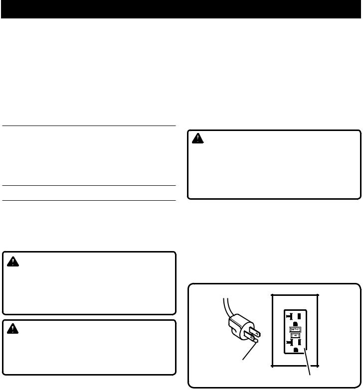
This product is for use on a nominal 120 V circuit and has a grounding plug similar to the plug illustrated below. Only connecttheproducttoanoutlethavingthesameconfiguration as the plug. Do not use an adapter with this product.
Grounding
Pin
GFCI recepticle
6 — English

|
FEATURES |
|
|
PRODUCT SPECIFICATIONS |
|
Flow Rate................................................................................................................................................................. |
0.24 GPM |
Pressure........................................................................................................................................................... |
800 - 2800 PSI |
Container Size.............................................................................................................................................................. |
3.5 gal. |
Input....................................................................................................................................... |
120 V, 60 Hz, AC only, 7.0 Amp |
Weight........................................................................................................................................................................... |
31 lbs. |
KNOW YOUR paint station
See Figure 1, page 15.
The safe use of this product requires an understanding of the information on the product and in this operator’s manual as well as a knowledge of the project you are attempting. Before use of this product, familiarize yourself with all operating features and safety rules.
3.5 GALLON Paint CONTAINER
The 3.5 gallon paint container can be removed and replaced with a 5 gallon or 1 gallon paint container for convenience and minimal clean up.
25 ft. high pressure hose
Paint station includes a 25 ft. high pressure hose to reach longer distances with the pistol-grip spayer or roller without having to move the paint station.
2800 PSI Piston Pump
Maintains pressure as needed for spraying and rolling. on-board accessory storage
Paint station includes on-board accessory storage for
convenient access to pistol-grip sprayer, spray tips, hose adapter and high pressure hose.
PAINT ROLLER
The paint roller accepts any 9 in. standard rollers up to 3/4 in. nap size.
PISTOL-GRIP SPRAYER
The pistol-grip sprayer provides a smooth finish. reversible spray tips
The unit includes two reversible sprays tips that will work for a wide variety of projects and prevents paint from clogging.
High/Low pressure dial
Variable pressure control to easily match pressure with the material being applied.
Lower pressure is for priming, cleaning and for thinner materials or rolling applications.
Higher pressure is ideal for latex and spraying applications.
ASSEMBLY |
|
|
UNPACKING |
loose parts LIST |
|
This product requires assembly. |
See figure 2, page 15. |
|
Carefully lift the product from the carton and place on a |
Description |
Qty. |
level work surface. |
Paint station with 3.5 gallon container and lid |
................1 |
|
Pistol-grip sprayer with nozzle tip guard......................... |
1 |
Warning: |
Roller head....................................................................... |
1 |
|
Roller handle.................................................................... |
1 |
Do not use this product if any parts on the Loose Parts |
|
|
|
9 in. roller......................................................................... |
1 |
List are already assembled to your product when you |
|
|
unpack it. Parts on this list are not assembled to the |
Roller cap......................................................................... |
2 |
product by the manufacturer and require customer instal- |
Wheel ............................................................................. |
2 |
lation. Use of a product that may have been improperly |
Axle.................................................................................. |
2 |
assembled could result in serious personal injury. |
Large washer.................................................................... |
2 |
|
Small washer.................................................................... |
2 |
Inspect the tool carefully to make sure no breakage or |
|
|
|
Hitch pin........................................................................... |
2 |
damage occurred during shipping. |
|
|
|
25 ft. grounded high pressure hose................................. |
1 |
Do not discard the packing material until you have care- |
|
|
|
415 Reversible spray tip.................................................. |
1 |
fully inspected and satisfactorily operated the tool. |
|
|
|
515 Reversible spray tip.................................................. |
1 |
If any parts are damaged or missing, please call |
|
|
1-800-525-2579 for assistance. |
Garden hose attachment................................................. |
1 |
|
Elastic strap..................................................................... |
1 |
|
Operator's manual (not shown)........................................ |
1 |
7 — English |
|
|

ASSEMBLY
Warning:
If any parts are damaged or missing do not operate this tool until the parts are replaced. Failure to heed this warning could result in serious personal injury.
warning:
Do not attempt to modify this tool or create accessories not recommended for use with this tool. Any such alteration or modification is misuse and could result in a hazardous condition leading to possible serious personal injury.
WARNING:
Do not connect to power supply until assembly is complete. Failure to comply could result in accidental starting and possible serious personal injury.
Tools needed
Adjustable wrench (2), 2 mm hex key
installing the Wheels
See Figure 3, page 16.
To attach the wheels to the base:n Locate the axle assembly.
n Slip the axle into the wheel hole. Slide small washer onto axle.
n Lifting the paint station slightly, slide the axle, wheel, and small washer into the wheel mounting hole in the machine base.
n Slide large washer onto the axle.
n Push the hitch pin into the hole on the end of the axle to secure assembly.
n Repeat with the second wheel assembly.
folding THE HANDLE
See Figures 4, page 16.
To raise the handle: pull the handle up until the handle release knob snaps through the locking hole to secure the handle in place.
To lower the handle (for storing): pull the handle release knob on the right side of handle and lower.
WARNING:
Never use the handle to lift the paint sprayer. Failure to heed this warning could result in serious personal injury.
CONNECTINGHighpressurehose/pistolgrip sprayer
See Figure 5, page 16.
To connect the high pressure hose to the paint station:
nScrew the collar on the high pressure hose onto the spray hose outlet located on the pump.
nTighten securely with an adjustable wrench.
To connect the pistol-grip sprayer to the high pressure hose:
nScrew the collar on the high pressure hose onto the pistol-grip sprayer by turning the hose collar clockwise.
nUse an adjustable wrench to hold the nut on the pistolgrip sprayer and another to turn and tighten the nut on hose end and tighten securely.
Installing reversable spray tip and nozzle tip guard on pistol-grip sprayer
See Figure 6, page 16.
See operator's instructions for flushing, priming and cleaning before installing nozzle tip guard and spray tip. Note all warnings regarding use of pistol-grip sprayer and the possibility of injection.
Turn lock-off thumbscrew counterclockwise to lock sprayer trigger.
Install nozzle seat and cap into nozzle tip guard.
Thread nozzle tip guard assembly onto sprayer and tighten securely.
Select spray tip and push securely into nozzle tip guard.
Keep pistol-grip sprayer trigger locked when not in use.
Installing Paint Roller
See Figure 7, page 16.
Place roller caps in each end of the paint roller.
Align pins in the end of each roller cap to the holes inside the roller head. Push out on the side of the roller head until the roller snaps into place.
8 — English

OPERATION
 WARNING:
Do not allow familiarity with this product to make you careless. Remember that a careless fraction of a second is sufficient to inflict serious injury.
WARNING:
Always wear eye protection marked to comply with ANSI Z87.1. Failure to do so could result in objects being thrown into your eyes resulting in possible serious injury.
WARNING:
Do not use any attachments or accessories not recommended by the manufacturer of this product. The use of attachments or accessories not recommended can result in serious personal injury.
AccEssories
All accessories used with this product must be rated greater than 3000 psi. Ensure compatibility and fit before using any accessory with this product.
Release Pressure procedure
Always follow this procedure when shutting paint station OFF for any reason. This procedure releases pressure in the high pressure hose.
On pistol-grip sprayer, turn lock-off thumbscrew counterclockwise to lock sprayer trigger.
Turn ON/OFF switch OFF.
Turn prime/spray lever to PRIME, as shown in figure 10. This releases pump pressure.
Unlock sprayer trigger and point to inside wall of paint container releasing unused paint or stain back into container. This releases pressure in the hose and pistol-grip sprayer.
Turn lock-off thumbscrew counterclockwise to lock sprayer trigger.
Leave prime/spray lever in the PRIME position until ready to spray again.
Flushing the paint station
Before using your new paint station or before beginning a new project or changing colors, it is important to thoroughly flush the paint station of any storage fluid, previous cleaning fluid, or material left in the system. Follow instructions for Cleaning the Paint Station before beginning any project.
WARNING:
Risk of fire or explosion - spray area must be well ventilated and away from spark of flames. Failure to heed this warning could result in serious personal injury.
APPLICATIONS
You may use this product for the purposes listed below:
Exterior painting and staining of decks, outdoor furniture, fences, and interior/exterior rolling of walls.
 WARNING:
To reduce the risk of injection NEVER change spray tip without locking the lock-out thumbscrew on the sprayer and never point sprayer at any part of the body, persons, or unit itself. In case of skin injection, seek medical attention immediately. Failure to heed this may cause serious personal injury.
Locking the pistol-grip sprayer
See Figure 8, page 16.
Always lock the pistol-grip sprayer trigger when you have stopped spraying to prevent the sprayer from being bumped or triggered accidentally and causing injection.
Turn lock-off thumbscrew counterclockwise to lock sprayer trigger.
Turn lock-off thumbscrew clockwise to unlock sprayer trigger.
Set up and Priming
See Figure 9-11, pages 16-17.
User must prime the pump and sprayer before beginning any spraying or rolling.
Fill the 3.5 gallon container with desired paint or stain. Place lid on container.
NOTE: Paint container may also be removed and replaced with 5 gallon paint container, 1 gallon square container or 1 gallon container. Secure container with elastic strap. Place lid on container.
Remove nozzle tip guard and spray tip from pistol-grip sprayer.
Place intake tube in paint container.
Set return tube over waste container to flush out waste material.
Turn prime/spray lever to PRIME.
Turn HIGH/LOW pressure control to LOW pressure.
Plug in the paint station.
Turn ON/OFF switch ON.
When material begins to flow through return tube set return tube into paint container and clip to intake tube.
Point pistol-grip sprayer (without guard and spray tip in place) into waste container.
Turn prime/spray lever to SPRAY.
Unlock sprayer trigger.
Turn HIGH/LOW pressure control from LOW to HIGH until pump starts.
9 — English

OPERATION
Spray into waste container until all air, water, cleaning fluid is expelled and only paint comes out.
NOTE: When the motor stops, this indicates that the pump and hoses are under pressure. If the motor continues to run, re-prime by turning the prime/spray lever to PRIME.
Turn lock-off thumbscrew counterclockwise to lock sprayer trigger.
Turn ON/OFF switch OFF.
Replace nozzle tip guard and reversible spray tip onto pistol-grip sprayer.
Unit is ready to spray.
Selecting a spray tip
See Figure 12, page 17.
Spray tips come in a variety of hole sizes and fan widths.
Your unit includes two reversible spray tips with a hole size of .015 in. that will work for a wide variety of applications. The 415 spray tip has a fan width of 8-10 in. The 515 spray tip has a fan width of 10-12 in.
HOLE SIZE: Spray tip hole size determines the flow rate, that is the amount of paint that is discharged from sprayer.
A larger hole size is best for thicker materials. A smaller hole size is best for thinner materials.
FAN SIZE: Fan width determines the size of the spray pattern when sprayer is held approximately 12 in. from surface to be painted.
A narrow fan width will provide thicker coverage of material and is better suited for small, tight areas.
A wide fan width will give thinner coverage of material and provide better coverage on large, broad areas.
Spray tip NUMBERS: When selecting a spray tip, the last three numbers of the spray tip number contains information on hole size and fan width.
For example if the spray tip number is 1415, the 4, when doubled is the approximate fan width of paint when applied 12 inches from surface. The last two numbers, 15, refer to the hole size in inches. In this case .015 in.
Tip |
|
|
Coatings |
|
|
||
Light |
|
Medium |
Heavy |
||||
hole |
|
||||||
size |
Stains |
Enamels |
Primers |
|
Interior |
Exterior |
|
|
|
Paints |
Paints |
||||
|
|
|
|
|
|
||
0.011 |
• |
|
|
|
|
|
|
|
|
|
|
|
|
|
|
0.013 |
• |
• |
|
|
|
|
|
|
|
|
|
|
|
|
|
0.015 |
|
• |
• |
|
|
• |
|
|
|
|
|
|
|
|
|
0.017 |
|
|
• |
|
|
• |
• |
|
|
|
|
|
|
|
|
0.019 |
|
|
• |
|
|
• |
• |
|
|
|
|
|
|
|
|
0.021 |
|
|
|
|
|
|
• |
Spray tip WEAR: It is important to replace or spray tips when they become worn. A worn spray tip will cause uneven
application and finish of material. Over time the spray tip hole size increases and the width of the fan spray decreases.
When using latex paint, spray tips need to be replaced between 15 and 40 gallons. For oil based materials, replace spray tips after 35 to 60 gallons of use.
To increase the life of your spray tips, use the lowest pressure setting needed to apply an even coating of material.
 WARNING:
This is a high pressure device. To reduce the risk of injury, user must read and understand operator's manual. To reduce the risk of injection do not point sprayer at any part of the body, persons, or unit itself. In case of skin injection, seek medical attention immediately. Failure to heed this may cause serious personal injury.
Spraying
See Figure 13, page 17.
Ensure surface to be painted is free of dust, dirt, and grease.
Mask or cover any areas not intended to be painted or stained. Be aware of wind that may cause your paint or stain to spray into areas not desired. Always use drop cloths or other cover to protect areas that are not intended to be painted or stained.
Select spray tip and seat securely into nozzle tip guard. Arrow on spray tip should face direction of spray.
Plug in the paint station.
Prime unit. Follow Set Up and Priming instructions.
Turn ON/OFF switch ON.
Turn prime/spray lever to SPRAY.
Turn HIGH/LOW pressure control clockwise to SPRAY icon (HIGH pressure). Pressure can be adjusted to reach desired spray pattern and coverage.
Unlock pistol-grip sprayer trigger. Begin spraying.
NOTE: If spray tip becomes clogged, turn 180° and spray into waste container to clear clog. Return spray tip to spray position and continue spraying.
Lock pistol-grip sprayer trigger and follow release pressure procedure when finished or stopping for any reason.
painting tips
See Figures 14-15, page 17.
Practice spraying on a piece of scrap material to test your spray pattern before beginning. If you cannot get a good spray pattern see Troubleshooting section.
To create an even coating over the entire surface:
•Keep the sprayer an even distance from the area being sprayed, about 12 inches from the spray tip of the sprayer to the surface being sprayed.
•Operate the sprayer in straight horizontal strokes. Do
10 — English
OPERATION
not hold the sprayer at an angle. This will result in uneven coverage.
•Depress the trigger to start the spray at the beginning of the stroke and release the trigger as you end the stroke. To prevent material build-up, do not keep the trigger depressed as you proceed to the next stroke.
•Make one pass for each stroke. Overlap strokes in halves for full coverage.
When finished, return any unused paint or stain to its original container and thoroughly clean the sprayer.
Painting with the roller attachment
See Figures 16-17, pages 17 - 18.
NOTE: The pistol-grip sprayer is used to control the flow of paint into the roller attachment. Pull the trigger only when more paint is needed on the roller.
Turn lock-off thumbscrew counterclockwise to lock pistolgrip sprayer trigger.
Turn off paint station and release pressure from spraying.
Assemble the 9 in. roller into the roller head according to the Installing Paint Roller.
Remove nozzle tip guard and spray tip from pistol-grip sprayer.
nThread roller handle onto sprayer (make sure rubber washer is in the roller handle before assembling).
nTighten securely with an adjustable wrench.
Snap roller head onto roller handle (make sure latches are completely engaged).
Turn ON/OFF switch ON.
Turn HIGH/LOW pressure control to ROLLING icon (LOW pressure).
Turn prime/spray lever to SPRAY.
Squeeze the trigger. Once the roller has paint, release the trigger and squeeze again only when more paint is needed.
NOTE: Do not continuously squeeze the trigger. For best results, after every third stroke, pull trigger for 1 second, release, then continue to paint.
To create an even coating over the entire surface:
•Apply paint or stain in an area several feet wide in a zig-zag direction.
•Roll back and forth repeatedly over the same area until the entire area is covered and the roller marks are smoothed out.
•If additional coats are necessary, let paint or stain dry completely between coats.
When finished, lock pistol-grip sprayer trigger and follow
Release Pressure Procedure.
Unplug the paint station.
 WARNING:
To reduce the risk of fire or explosion: Do not use with flammable liquids (i.e., paint stripper, paint remover, brush cleaner, mineral spirits, lacquer thinner, turpentine, acetone, gasoline, kerosene, etc.). Use only water (for water based paints) or Klean Strip® Revolutionary White Formula Paint Thinner (for oil-based paints or varnish).
Overnight storage (UP to 12 hours)
NOTE: These instructions are for latex paint and water based materials only. If you are using oil-based material, refer to
Cleaning the Paint Station and Long Term Storage for instructions. Stains and oil based materials do not keep for any extended period of time.
Lock pistol-grip sprayer and follow Release Pressure
Procedure.
Turn ON/OFF switch OFF.
Unplug the paint station.
Leave intake tube and return tube in paint.
Gently pour 1/2 cup water over top of paint to prevent drying.
Close lid on 3.5 gallon container. Wrap damp cloth around tubes and over opening of container. If using 5 gallon or other container, wrap tubes and container with plastic to seal out air.
Wrap pistol-grip sprayer with damp cloth and place in plastic bag. Seal bag.
Store for short time out of sunlight. For longer storage, follow instructions for Cleaning the Piant Station.
cleaning the paint station
See Figures 18-19, page 18.
The solution used to clean the sprayer is determined by the type of material that has been sprayed. For anything other than latex material use Klean Strip® Revolutionary White Formula Paint Thinner (for oil-based paints or varnish).
Caution:
It is important to thoroughly clean paint station and pistol-grip sprayer after each use or when changing paint color. Allowing paint or stain to remain in an idle tool for an extended period of time can cause its hoses to clog and its moving parts to seize.
Always use drop cloths or other cover to protect areas from possible spills.
Lock pistol-grip sprayer and follow Release Pressure
Procedure.
Unplug the paint station.
Remove the spray tip and nozzle tip guard from sprayer.
11 — English

OPERATION
Use spray tip cleaning brush to clean material from spray tip holes.
Soak spray tip(s) and nozzle tip guard in water (for water based paints) or Klean Strip® Revolutionary White Formula Paint Thinner (for oil-based paints or varnish), rinse.
Return any unused paint or stain to its original container. If using paint station container, rinse clean with water (for water based paints) or Klean Strip® White Formula Paint Thinner (for oil-based paints or varnish). Empty into waste container.
Remove filter from intake tube, soak in cleaning fluid and rinse.
Fill paint station container with water (for water based paints) or Klean Strip® Revolutionary White Formula Paint Thinner (for oil-based paints or varnish).
NOTE: If flushing or cleaning using water for water based materials, It may be easier to use a garden hose and the garden hose attachment (included). Remove filter from intake tube and attach intake tube to garden hose with attachment.
Place intake tube to paint station container.
Place return tube in original paint container.
Place original paint container right next to waste container.
Turn prime/spray lever to PRIME.
Turn HIGH/LOW pressure control counterclockwise to LOW pressure.
Turn ON/OFF switch ON.
The paint station will draw cleaning fluid up the intake tube through the pump and out the return tube into the paint container. Move the return tube from the paint container to the waste container as soon as the cleaning fluid starts to come out of the return tube.
Turn prime/spray lever to SPRAY.
Unlock pistol-grip sprayer.
Point pistol-grip sprayer at the interior side of original paint container to run out paint in system so as not to waste paint.
Move the pistol-grip sprayer from the paint container to the waste container as soon as the cleaning fluid starts to come out sprayer.
Let fluid run through system for at least 1 minute (until clean fluid is noticed).
NOTE: If using the garden hose adapter, turn on garden hose and run water through system until water runs clear.
Leave system running for approximately one minute or until cleaning fluid runs clear.
Turn prime/spray lever to PRIME.
Turn ON/OFF switch OFF.
Unplug the paint station
Dispose of dirty water (or Klean Strip® Revolutionary White Formula Paint Thinner) in accordance with federal, state, and local ordinances.
To clean the paint roller:
Always use drop cloths or other cover to protect areas from possible spills.
Disconnect the roller head from the roller handle and pour the remaining paint or stain from the roller head and roller handle into the original container.
Thoroughly clean the roller and accessories by soaking and rinsing in water (for water based paints) or Klean Strip® Revolutionary White Formula Paint Thinner (for oil-based paints or varnish).
Cleaning the pistol-grip sprayer filter
See Figure 20, page 18.
Shut down the paint station using Release Pressure
Procedure.
Unplug the paint station.
Check that pistol-grip sprayer trigger is locked off.
Remove pistol-grip sprayer from the high pressure hose using two adjustable wrenches.
Unscrew hex socket screw and lock nut to release trigger guard from plate on the base of sprayer.
Using wrench, turn handle counterclockwise to remove.
Remove filter from handle, noting direction of filter.
Thoroughly clean filter container with water (for water based paints) or Klean Strip® Revolutionary White Formula Paint Thinner (for oil-based paints or varnish).
If filter has any holes, replace with new filter. NEVER puncture filter with any object.
Replace filter in handle, tapered end down facing back of sprayer. Sprayer will not work if filter is improperly inserted in handle.
Reassemble pistol-grip sprayer in reverse order, tighten securely.
12 — English

MAINTENANCE
 WARNING:
When servicing, use only identical replacement parts. Use of any other parts may create a hazard or cause product damage.
 WARNING:
Always wear eye protection with side shields marked to comply with ANSI Z87.1. Failure to do so could result in fluids entering your eyes resulting in possible serious injury.
maintenance procedures
Avoid using solvents when cleaning plastic parts. Most plastics are susceptible to damage from various types of commercial solvents and may be damaged by their use. Use clean cloths to remove dirt, dust, oil, grease, etc.
 WARNING:
Do not at any time let brake fluids, gasoline, petroleum based products, penetrating oils, etc., come in contact with plastic parts. Chemicals can damage, weaken, or destroy plastic which may result in serious personal injury.
long-term storage
See Figure 22, page 18.
When storing the paint station for 16 hours or more, a thorough cleaning is recommended.
Shutdown paint station.
Thoroughly clean paint station and sprayer according to instructions.
Be sure that machine and tubes are clear any water or fluid as these may freeze.
Coil 25 ft. high pressure hose and store on back of tool with hook and loop straps.
Keep intake tube and prime tube in 3.5 gallon paint container. Store filter and sprayer in plastic bag and seal.
Fold handle over front of tool.
13 — English

troubleshooting
Problem |
Cause |
Possible Solution |
Motor does not run. |
Paint station is not plugged in |
Make sure unit is plugged in |
|
On/Off switch in OFF position |
Turn On/Off switch to ON |
|
Paint station has shut off while under |
Turn the high/low pressure knob to |
|
pressure |
maximum pressure or release pressure by |
|
|
turning Prime/Spray lever to Prime |
|
No current coming from outlet |
Test the power supply voltage |
|
Extension cord is damaged or has low |
Replace extension cord |
|
voltage |
|
|
A fuse has blown on paint station |
Contact Authorized Service center |
|
Motor is not working properly |
Contact Authorized Service Center |
|
|
|
Pressure setting is too low |
HIGH/LOW pressure control set too |
Turn HIGH/LOW pressure control |
|
high. |
clockwise |
|
|
|
Pump does not prime |
Prime/Spray valve is in Spray position |
Turn Prime/Spray lever to Prime |
|
Inlet screen is clogged or intake tube |
Clean debris off inlet screen and make |
|
is not immersed |
sure intake tube is at bottom of paint |
|
|
bucket |
|
Inlet valve check ball is stuck |
Tap firmly on the outside of the inlet valve |
|
|
|
|
|
with a small wrench, allowing pump to |
|
|
prime properly |
|
|
Remove intake tube and place a pencil |
|
|
into the inlet section to dislodge the ball, |
|
|
allowing pump to prime properly. |
|
Intake tube is loose |
Tighten intake tube with flat-head |
|
|
screwdriver |
|
|
|
Paint station starts but does not |
Paint container is empty or intake tube |
Fill paint container with material and |
circulate paint when Prime/Spray |
is not fully submerged in fluid |
submerge intake tube into material |
lever is turned to Prime |
Suction filter is clogged |
Clean suction filter |
|
||
|
Prime/Spray valve is clogged |
Contact Authorized Service Center |
|
|
|
Motor seems to be running properly |
Reversible spray tip is worn |
Replace spray tip |
but pressure drops when pistol-grip |
Spray tip is clogged |
Turn spray tip 180° and spray to clean |
is triggered |
Suction tube and filter are loose or |
Reinstall or replace suction tube and filter |
|
||
|
damaged |
as needed |
|
Pistol-grip sprayer filter is clogged |
Clean or replace pistol-grip sprayer filter |
|
Material being sprayed is too thick |
Follow material manufacturer’s directions |
|
|
and thin material as needed |
|
Inlet valve is damaged or worn |
Replace inlet valve |
|
Intake tube is loose |
Tighten intake tube |
|
|
|
Prime/spray lever is set to spray but |
Prime/spray lever is dirty or damaged |
Contact Authorized Service Center |
there is flow through the prime tube |
|
|
|
|
|
Pistol-grip sprayer leaks |
Internal sprayer parts are worn or |
Contact Authorized Service Center |
|
damaged |
|
|
|
|
14 — English

troubleshooting
Problem |
Cause |
Possible Solution |
|
|
|
Nozzle tip guard leaks |
Nozzle tip guard or spray tip where |
Reassemble according to nozzle tip guard |
|
assembled improperly |
and Spray tip assembly instructions. |
|
|
|
Pistol-grip sprayer will not spray |
Spray tip is clogged |
Turn spray tip 180° and spray to clean |
|
Pistol-grip sprayer filter is clogged |
Clean or replace pistol-grip sprayer filter |
|
Spray tip is not fully seated into nozzle |
Reassemble according to nozzle tip guard |
|
tip guard |
and Spray tip assembly instructions. |
|
|
|
Paint pattern is weak or uneven |
Pressure is set to low |
Turn High-low pressure knob clockwise |
|
|
to increase pressure |
|
Pistol-grip sprayer or intake tube filter |
Clean or replace filters |
|
is clogged |
|
|
Intake tube is loose at inlet valve |
Tighten tube fitting |
|
Spray tip is worn |
Replace spray tip |
|
Material being sprayed is too thick |
Follow material manufacturer’s directions |
|
|
and thin material as needed |
|
Loss of pressure |
See Cause/Possible solutions for |
|
|
|
|
|
"Pressure setting is too low," and |
|
|
"Motor seems to be running properly |
|
|
but pressure drops when pistol-grip is |
|
|
triggered" |
|
|
|
NOTE: FIGURES (ILLUSTRATIONS) START ON PAGE 16 AFTER
SPANISH LANGUAGE SECTION.
15 — English
 Loading...