


RY15122
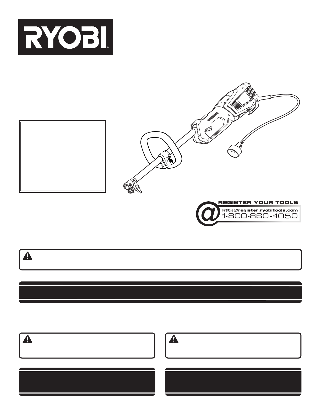
OPERATOR’S MANUAL
ELECTRIC POWER HEAD
BLOC-MOTEUR DE ÉLECTRIQUE
CABEZAL MOTOR ELÉCTRICA
RY15122 / RY15123
To register your Ryobi
product, please visit:
http://register.ryobitools.com/
Pour enregistrer votre produit
de Ryobi, s’il vous plaît la visite:
http://register.ryobitools.com/
Para registrar su producto de
Ryobi, por favor visita:
http://register.ryobitools.com/
MANUEL D’UTILISATION
MANUAL DEL OPERADOR
Your power head has been engineered and manufactured to our high standard for dependability, ease of operation, and
operator safety. When properly cared for, it will give you years of rugged, trouble-free performance.
WARNING: To reduce the risk of injury, the user must read and understand the operator’s manual before using
this product.
Thank you for your purchase.
SAVE THIS MANUAL FOR FUTURE REFERENCE
Ce bloc-moteur a été conçu et fabriqué conformément à nos
strictes normes de fiabilité, simplicité d’emploi et sécurité
d’utilisation. Correctement entretenu, cet outil vous donnera des
années de fonctionnement robuste et sans problème.
AVERTISSEMENT : Pour réduire les risques de
blessures, l’utilisateur doit lire et veiller à bien comprendre le
manuel d’utilisation avant d’employer ce produit.
Merci de votre achat.
CONSERVER CE MANUEL POUR
FUTURE RÉFÉRENCE
Su cabezal motor ha sido diseñado y fabricado de conformidad con
nuestras estrictas normas para brindar fiabilidad, facilidad de uso
y seguridad para el operador. Con el debido cuidado, le brindará
muchos años de sólido funcionamiento y sin problemas.
ADVERTENCIA: Para reducir el riesgo de lesiones,
el usuario debe leer y comprender el manual del operador antes
de usar este producto.
Le agradecemos su compra.
GUARDE ESTE MANUAL PARA
FUTURAS CONSULTAS

See this fold-out section for all of the figures
referenced in the operator’s manual.
Consulter l’encart à volets afin d’examiner
toutes les figures mentionnées dans le manuel
d’utilisation.
Consulte esta sección desplegable para ver todas
las figuras a las que se hace referencia en el
manual del operador.
ii
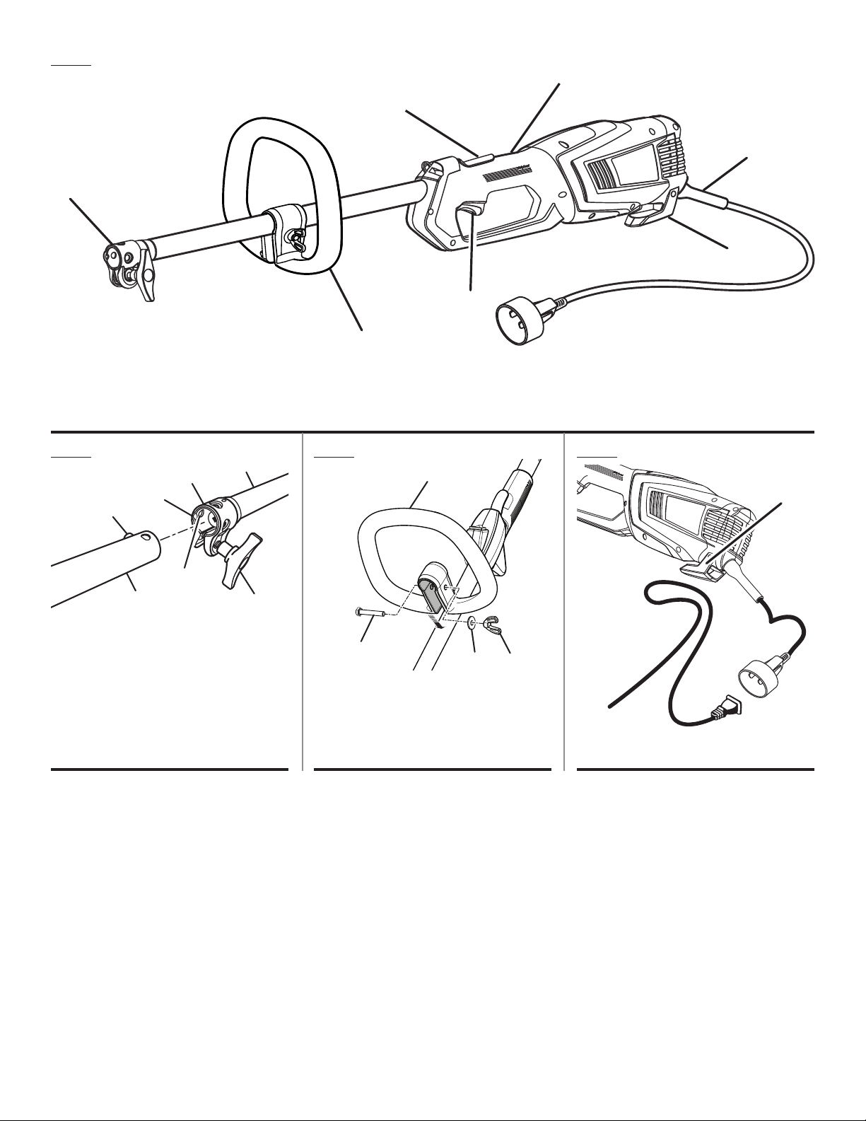
Fig. 1
A
D
G
F
E
C
B
A - Coupler (coupleur, acoplador)
B - Front handle (poignée avant, mango delantero)
C - Switch trigger (gâchette de commutateur, gatillo del interruptor)
D - Rear handle (poignée arrière, mango trasero)
Fig. 2
Fig. 3
D
C
B
A
A
F
G
A - Button (bouton, botón)
B - Guide recess (logement guide, hueco guía)
C - Coupler (coupleur, acoplador)
D - Power head shaft (arbre du bloc moteur, eje
del cabezal motor)
E - Knob (bouton, perilla)
F - Positioning hole (trou de positionnement,
orificio de posicionamiento)
G - Attachment shaft (arbre d’accessoire, eje del
aditamento)
E
A
A - Bolt (boulon, perno)
B - Front handle (poignée avant, mango
delantero)
C - Washer (rondelle, arandela)
D - Wing nut (écrou papillon, tuerca de
mariposa)
E - Cord retainer (retenue de cordon, retén para el cordón)
F - Cord bend relief (soulagement de torsion du cordon, protector del cordón)
G - Lock-out button (bouton de verrouillage, botón del seguro de apagado)
Fig. 4
B
C
D
A - Cord retainer (retenue de cordon, retén para
el cordón)
A
iii
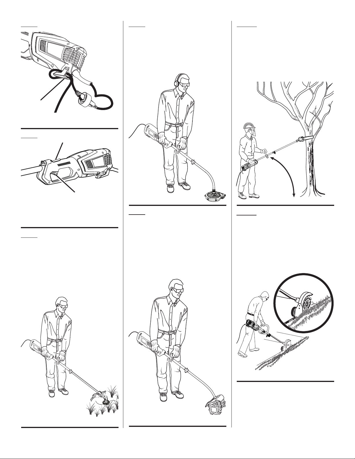
Fig. 5
A
A - Cord retainer (retenue de cordon, retén para
el cordón)
PROPER BLOWER ATTACHMENT
OPERATING POSITION
ACCESSOIRE SOUFFLANTE
POSITION DE TRAVAIL
POSICIÓN CORRECTA PARA EL
MANEJO DE ADITAMENTO PARA SOPLADOR
Fig. 10Fig. 8
PROPER PRUNER ATTACHMENT
OPERATING POSITION
ACCESSOIRE ÉLAGUEUSE POSITION
DE TRAVAIL
POSICIÓN CORRECTA PARA EL MANEJO DE
ADITAMENTO PARA PODADORA
Fig. 6
B
A
A - Switch trigger (gâchette de commutateur,
gatillo del interruptor)
B - Lock-out button (bouton de verrouillage,
botón del seguro de apagado)
Fig. 7
PROPER STRAIGHT SHAFT TRIMMER
ATTACHMENT OPERATING POSITION
ACCESSOIRE TAILLE-BORDURES À ARBRE
DROIT POSITION DE TRAVAIL
POSICIÓN CORRECTA PARA EL MANEJO
DE ADITAMENTO PARA RECORTADORA
DE EJE RECTO
Fig. 9
PROPER TILLER ATTACHMENT
OPERATING POSITION
ACCESSOIRE CULTIVATEUR
POSITION DE TRAVAIL
POSICIÓN CORRECTA PARA EL
MANEJO DE ADITAMENTO PARA CULTIVAR
Fig. 11
PROPER EDGER ATTACHMENT
OPERATING POSITION
ACCESSOIRE COUPE-BORDURES
POSITION DE TRAVAIL
POSICIÓN CORRECTA PARA EL
ACCESORIO PARA CORTAR BORDES
iv

Fig. 12
PROPER CURVED SHAFT TRIMMER
ATTACHMENT OPERATING POSITION
ACCESSOIRE TAILLE-BORDURES À ARBRE
COURBÉE POSITION DE TRAVAIL
POSICIÓN CORRECTA PARA EL MANEJO
DE ADITAMENTO PARA RECORTADORA
DE EJE CURVO
v

TABLE OF CONTENTS
TABLE DES MATIÈRES / ÍNDICE DE CONTENIDO
Introduction ......................................................................................................................................................................2
Introduction / Introducción
Important Safety Instructions ........................................................................................................................................ 3-4
Instructions importantes concernant la sécurité / instrucciones de seguridad importantes
Symbols .........................................................................................................................................................................5-6
Symboles / Símbolos
Electrical ........................................................................................................................................................................ 6-7
Caractéristiques électriques / Aspectos eléctricos
Features ............................................................................................................................................................................7
Caractéristiques / Características
Assembly .......................................................................................................................................................................7-8
Assemblage / Armado
Operation .....................................................................................................................................................................9-10
Utilisation / Funcionamiento
Maintenance ................................................................................................................................................................... 10
Entretien / Mantenimiento
Troubleshooting .............................................................................................................................................................. 10
Dépannage / Solución de problemas
Warranty .........................................................................................................................................................................11
Garantie / Garantía
Parts Ordering and Service ...............................................................................................................................Back Page
Commande de pièces et réparation / Pedidos de piezas y servicio ......................................................... Page arrière / Pág. posterior
INTRODUCTION
INTRODUCTION / INTRODUCCIÓN
This product has many features for making its use more pleasant and enjoyable. Safety, performance, and dependability
have been given top priority in the design of this product making it easy to maintain and operate.
* * *
Ce produit offre de nombreuses fonctions destinées à rendre son utilisation plus plaisante et satisfaisante. Lors de la
conception de ce produit, l’accent a été mis sur la sécurité, les performances et la fiabilité, afin d’en faire un outil facile à
utiliser et à entretenir.
* * *
Este producto ofrece numerosas características para hacer más agradable y placentero su uso. En el diseño de este producto
se ha conferido prioridad a la seguridad, el desempeño y la fiabilidad, por lo cual se facilita su manejo y mantenimiento.
2

IMPORTANT SAFETY INSTRUCTIONS
WARNING!
Read and understand all instructions before using this
product. Failure to follow all instructions listed below may
result in electric shock, fire and/or serious personal injury.
Do not use without guard and handle in place.
READ ALL INSTRUCTIONS
For safe operation, read and understand all instructions
before using this product. Follow all safety instructions.
Failure to follow all safety instructions listed below, can
result in serious personal injury.
Do not allow children or untrained individuals to use this
unit.
Check the work area before each use. Remove all objects
such as rocks, broken glass, nails, wire, or string which
can be thrown or become entangled in the machine.
Use Safety Glasses – Always wear eye protection with
side shields marked to comply with ANSI Z87.1. Failure
to do so could result in objects being thrown into your
eyes, resulting in possible serious injury.
Always wear safety glasses with side shields. Everyday
glasses have only impact resistant lenses. They are NOT
safety glasses. Following this rule will reduce the risk of
eye injury. Use face mask if operation is dusty.
Dress Properly – Use rubber gloves and substantial
footwear is recommended when working outdoors. Wear
heavy long pants, long sleeves, boots, and gloves. Do not
wear loose-fitting clothing, short pants, sandals, jewelry
of any kind, or go barefoot.
Secure long hair above shoulder level to prevent entangle-
ment in moving parts.
Keep children away – Keep all bystanders, children, and
pets at least 50 ft. away.
Stay alert – Do not operate this unit when you are tired,
ill, or under the influence of alcohol, drugs, or medication.
Do not operate in poor lighting.
Keep all parts of your body away from any moving part.
Do not operate power tools in explosive atmospheres,
such as in the presence of flammable liquids, gases, or
dust. Power tools create sparks which may ignite the dust
or fumes.
To reduce the risk of electric shock, this tool has a po-
larized plug (one blade is wider than the other) and will
require the use of a polarized extension cord. The plug
will fit into a polarized extension cord only one way. If the
plug does not fit fully into the extension cord, reverse the
plug. If the plug still does not fit, obtain a correct polarized
extension cord. A polarized extension cord will require
the use of a polarized wall outlet. This plug will fit into the
polarized wall outlet only one way. If the plug does not fit
fully into the wall outlet, reverse the plug. If the plug still
does not fit, contact a qualified electrician to install the
proper wall outlet. Do not change the equipment plug,
extension cord receptacle, or extension cord plug in any
way.
Avoid body contact with grounded surfaces such as pipes,
radiators, ranges, and refrigerators. There is an increased
risk of electric shock if your body is grounded.
Avoid Dangerous Environments – Don’t expose power
tools to rain or wet conditions. Water entering a power
tool will increase the risk of electric shock.
Warning – To reduce the risk of electric shock - Use out-
door extension cords marked W-A, W, SW-A, SOW-A,
STW-A, STOW-A, SJW-A, SJTW-A, or SJTOW-A. These
cords are rated for outdoor use and reduce the risk of
electric shock.
Ground Fault Circuit Interrupter (GFCI) protection should
be provided on the circuit(s) or outlet(s) to be used for the
gardening appliance. Receptacles are available having
built-in GFCI protection and may be used for this measure
of safety.
Use Right Appliance - Do not force tool. Use the correct
tool for your application. The correct tool will do the job
better and safer at the rate for which it is designed.
Do not operate the equipment while barefoot or when
wearing sandals or similar lightweight footwear. Wear
protective footwear that will protect your feet and improve
your footing on slippery surfaces.
Do not use on a ladder or unstable support. Stable foot-
ing on a solid surface enables better control of the unit
in unexpected situations.
Do Not Overreach – Keep firm footing and balance. Over-
reaching can result in loss of balance.
Avoid Unintentional Starting – Do not carry plugged in
appliance with finger on trigger. Be sure the switch trigger
is not engaged before plugging in.
Do not use tool if switch trigger does not turn it on or off.
Any tool that cannot be controlled with the switch trigger
is dangerous and must be repaired.
Disconnect Appliance – Remove appliance from power
source before storing, servicing, changing accessories
such as cutting line. Such preventive safety measures
reduce the risk of starting the tool accidentally.
Use only identical manufacturer’s replacement parts and
accessories. Use of any other parts may create a hazard
or cause product damage.
Maintain appliance with care – Replace string head if
cracked, chipped, or damaged in any way. Be sure the
string head is properly installed and securely fastened.
Keep cutting edge sharp and clean for best performance
and to reduce the risk of injury. Follow instructions for
lubricating and changing accessories. Inspect appliance
3 — English

IMPORTANT SAFETY INSTRUCTIONS
cord periodically, and if damaged, have it repaired by
an authorized service facility. Inspect extension cords
periodically and replace if damaged. Keep handles dry,
clean, and free from oil and grease. Failure to do so can
cause serious injury.
Make sure all guards, straps, deflectors and handles are
properly and securely attached.
Never use flailing devices, wire, or rope on any attachment.
Use only the manufacturer’s replacement string in the
cutting head when using a string trimmer attachment.
Do not use any other cutting attachment, for example,
metal wire, rope, or the like. To install any other brand of
cutting head to the string trimmer can result in serious
personal injury.
Never operate unit without the grass deflector in place
and in good condition.
Check damaged parts – Before further use of the tool, a
guard or other part that is damaged should be carefully
checked to determine that it will operate properly and
perform its intended function. Check for alignment of
moving parts, binding of moving parts, breakage of parts,
mounting and any other conditions that may affect its
operation. A guard or other part that is damaged must
be properly repaired or replaced by an authorized service
center to avoid risk of personal injury.
Maintain a firm grip on both handles while trimming. Keep
string head below waist level. Never cut with the string
head located over 30 in. or more above the ground.
Store idle appliances - When not in use, power head
should be stored indoors in a dry, locked place out of
the reach of children. Do not allow appliance to be used
as a toy. Close attention is necessary when used near
children.
Extension Cord - Make sure your extension cord is in
good condition. When using an extension cord, be sure to
use one heavy enough to carry the current your product
will draw. A wire gauge size (A.W.G.) of at least 14 is
recommended for an extension cord 50 feet or less in
length. A cord exceeding 100 feet is not recom mended.
If in doubt, use the next heavier gauge. The smaller the
gauge number, the heavier the cord. An undersized cord
will cause a drop in line voltage resulting in loss of power
and overheating.
Turn off controls before unplugging.
Keep the air vents clean and free of debris to avoid
overheating the motor. Clean after each use.
Stop the unit and disconnect the power source when not
in use. Carry the unit with the motor stopped.
Store unplugged and out of the reach of children when
not in use.
Do not hang unit so that the switch trigger is depressed.
Do not use multiple cords.
Do not abuse the cord – Never carry the unit by the
extension cord or yank extension cord to disconnect unit.
Keep the cord clear of operator and obstacles at all times.
Do not expose cords to heat, oil, water, or sharp edges.
Do not handle plug with wet hands.
If the power supply cord is damaged, it must be replaced
only by the manufacturer or by an authorized service
center to avoid risk.
If appliance is not working as it should , has been dropped,
damaged, dropped into water, return it to service center.
Don’t grasp the exposed cutting blades or cutting edges
when picking up or holding the appliance.
Don’t Force Appliance – It will do the job better and with
less likelihood of a risk of injury at the rate for which it
was designed.
Danger – Risk of Cut – Keep Hands Away From Blades –
Keep both hands on handles when power is on. Do not
attempt to remove cut material nor hold material to be
cut when blades are moving. Make sure trimmer switch
is off when clearing jammed material from blades.
Caution – blades coast after turn off.
When operating the trimmer keep extension cord behind
trimmer.
Do not put any objects into openings. Do not use with
any openings blocked, keep free of dust, lint, hair and
anything that may reduce air flow.
Save these instructions. Refer to them frequently and
use them to instruct others who may use this power tool.
If you loan someone this power tool, loan them these
instructions also.
ADDITIONAL SPECIFIC SAFETY RULES CAN BE FOUND IN THE
APPLICABLE ATTACHMENT’S OPERATOR’S MANUAL
4 — English
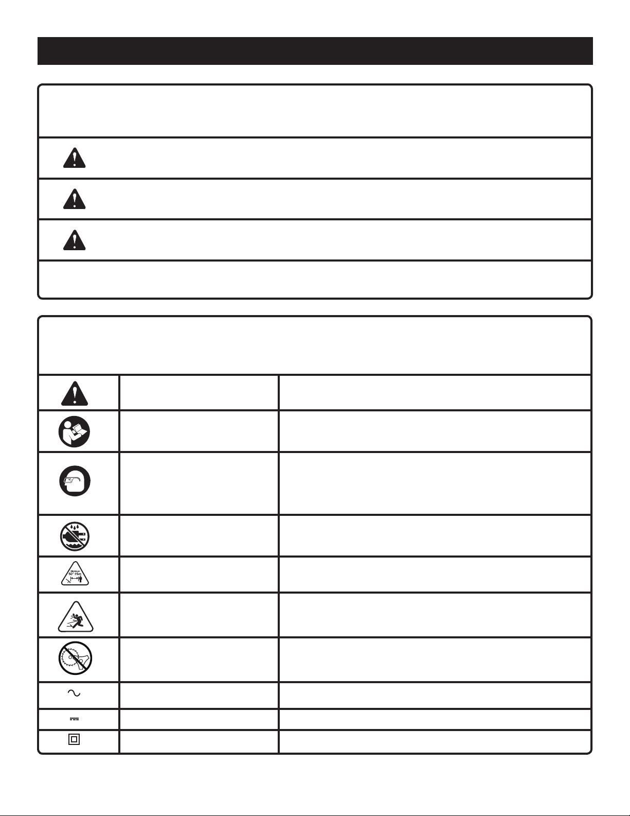
SYMBOLS
The following signal words and meanings are intended to explain the levels of risk associated with this product.
SYMBOL SIGNAL MEANING
DANGER:
WARNING:
CAUTION:
CAUTION:
Some of the following symbols may be used on this product. Please study them and learn their meaning. Proper interpretation of these symbols will allow you to operate the product better and safer.
Indicates an imminently hazardous situation, which, if not avoided, will result
in death or serious injury.
Indicates a potentially hazardous situation, which, if not avoided, could result
in death or serious injury.
Indicates a potentially hazardous situation, which, if not avoided, may result in
minor or moderate injury.
(Without Safety Alert Symbol) Indicates a situation that may result in property
damage.
SYMBOL NAME DESIGNATION/EXPLANATION
Safety Alert
Read The Operator’s Manual
Indicates a potential personal injury hazard.
To reduce the risk of injury, user must read and understand
operator’s manual before using this product.
Eye Protection
Wet Conditions Alert
Keep Bystanders Away
Ricochet
No Blade
Alternating Current
Direct Current
Class II Construction
Always wear eye protection with side shields marked to comply with
ANSI Z87.1. Hearing and/or head protection may also be required
depending on the type of attachment used and as prescribed in
the attachment’s Operator’s Manual.
Do not expose to rain or use in damp locations.
Keep all bystanders at least 50 ft. away.
Thrown objects can ricochet and result in personal injury or
property damage.
Do not install or use any type of blade on a product displaying
this symbol.
Type of current
Type or a characteristic of current
Double-insulated construction
5 — English

SYMBOLS
Some of the following symbols may be used on this product. Please study them and learn their meaning. Proper interpretation of these symbols will allow you to operate the product better and safer.
SYMBOL NAME DESIGNATION/EXPLANATION
V
A
Hz
W
min
Volts
Amperes
Hertz
Watt
Minutes
Voltage
Current
Frequency (cycles per second)
Power
Time
ELECTRICAL
DOUBLE INSULATION
Double insulation is a concept in safety in electric power
tools, which eliminates the need for the usual threewire grounded power cord. All exposed metal parts are
isolated from the internal metal motor components with
protecting insulation. Double insulated tools do not need
to be grounded.
WARNING:
The double insulated system is intended to protect
the user from shock resulting from a break in the tool’s
internal insulation. Observe all normal safety precautions
to avoid electrical shock.
ELECTRICAL CONNECTION
This product has a precision-built electric motor. It should
be connected to a power supply that is 120 V, AC only
(normal household current), 60 Hz. Do not operate this
product on direct current (DC). A substantial voltage drop
will cause a loss of power and the motor will overheat. If
the product does not operate when plugged into an outlet,
double-check the power supply.
GFCI
Ground Fault Circuit Interrupter (GFCI) protection should
be provided on the circuit(s) or outlet(s) to be used for the
product. Receptacles are available having built-in GFCI
protection and may be used for this measure of safety.
NOTE: Servicing of a product with double insulation requires
extreme care and knowledge of the system and should
be performed only by a qualified service technician. For
service, we suggest you return the product to your nearest authorized service center for repair. Always use original
factory replacement parts when servicing.
6 — English
EXTENSION CORDS
When using a power tool at a considerable distance from
a power source, be sure to use an extension cord that has
the capacity to handle the current the product will draw. An
undersized cord will cause a drop in line voltage, resulting in
overheating and loss of power. Use the chart to determine
the minimum wire size required in an extension cord. Only
round jacketed cords listed by Underwriter’s Laboratories
(UL) should be used.

ELECTRICAL
When working outdoors with a product , use an extension
cord that is designed for outside use. This type of cord is
designated with “W-A” or “W” on the cord’s jacket.
Before using any extension cord, inspect it for loose or
exposed wires and cut or worn insulation.
**Ampere rating (on product data plate)
0-2.0 2.1-3.4 3.5-5.0 5.1-7.0 7.1-12.0 12.1-16.0
Cord Length Wire Size (A.W.G.)
WARNING:
Keep the extension cord clear of the working area.
Position the cord so that it will not get caught on
lumber, tools, or other obstructions while you are working
with a power tool. Failure to do so can result in serious
personal injury.
25’ 16 16 16 16 14 14
50’ 16 16 16 14 14 12
100’ 16 16 14 12 10 —
**Used on 12 gauge - 20 amp circuit.
NOTE: AWG = American Wire Gauge
WARNING:
Check extension cords before each use. If damaged
replace immediately. Never use the product with a
damaged cord since touching the damaged area could
cause electrical shock resulting in serious injury.
FEATURES
PRODUCT SPECIFICATIONS
Operating RPM .................................................................................................................................................10,745 (RPM)
Input ....................................................................................................................................120 V, 60 Hz, AC only, 10 Amps
Net Weight ..................................................................................................................................................................7.0 lbs.
KNOW YOUR PRODUCT
See Figure 1.
The safe use of this product requires an understanding of
the information on the tool and in this operator’s manual
as well as a knowledge of the project you are attempting.
Before use of this product, familiarize yourself with all operating features and safety rules, in both this manual and the
operator’s manuals for all attachments that your are using
with this power head.
CORD RETAINER
The cord retainer helps prevent accidental unplugging of
the extension cord.
LOCK-OUT BUTTON
The lock-out button reduces the possibility of accidental
starting.
FRONT HANDLE
The power head is equipped with a front handle assembly
for ease of operation and to prevent loss of control.
ASSEMBLY
UNPACKING
This product requires assembly.
Carefully remove the product and any accessories from
the box. Make sure that all items listed in the packing list
are included.
WARNING:
Do not use this product if any parts on the packing list
are already assembled to your product when you unpack
it. Parts on this list are not assembled to the product by
the manufacturer and require customer installation. Use
of a product that may have been improperly assembled
could result in serious personal injury.
7 — English
Inspect the product carefully to make sure no breakage
or damage occurred during shipping.
Do not discard the packing material until you have carefully
inspected and satisfactorily operated the product.
If any parts are damaged or missing, please call
1-800-860-4050 for assistance.
PACKING LIST
Power Head
Front Handle with Hardware
Operator’s Manual
 Loading...