


RY28025

OPERATOR’S MANUAL
MANUEL D’UTILISATION
MANUAL DEL OPERADOR
CS26
RY28025
26CC STRING TRIMMERS
TAILLE-BORDURES À LIGNE DE 26 CC
RECORTADORAS DE HILO 26 CC
ALL VERSIONS
TOUTES LES VERSIONS
TODAS LAS VERSIONES
NOTICE AVIS AVISO
Do not use E15 or E85 fuel (or fuel containing greater than 10% ethanol) in this product. It is a violation of federal law and will damage the unit and void your warranty.
Ne pas utiliser d’essence E15 ou E85 (ou un carburant contenant plus de 10 % d’éthanol) dans ce
produit. Une telle utilisation représente une violation de la loi fédérale et endommagera l’appareil et annulera la garantie.
No utilice combustibles E15 o E85 (ni combustibles que contengan más de 10 % de etanol) con este producto. Esto constituye
una violación a la ley federal, dañará la unidad y anulará la garantía.
Your trimmer has been engineered and manufactured to our high standard for dependability, ease of operation, and operator safety. When properly cared for, it will give you years of rugged, trouble-free performance.
WARNING: To reduce the risk of injury, the user must read and understand the operator’s manual before using
this product.
SS26
RY28045
Thank you for your purchase.
SAVE THIS MANUAL FOR FUTURE REFERENCE
Ce taille-bordures a été conçu et fabriqué conformément à
nos strictes normes de fiabilité, simplicité d’emploi et sécurité
d’utilisation. Correctement entretenu, cet outil vous donnera des
années de fonctionnement robuste et sans problème.
AVERTISSEMENT : Pour réduire les risques de
blessures, l’utilisateur doit lire et veiller à bien comprendre le
manuel d’utilisation avant d’employer ce produit.
Merci de votre achat.
CONSERVER CE MANUEL POUR
FUTURE RÉFÉRENCE
Su recortadora ha sido diseñado y fabricado de conformidad con
nuestras estrictas normas para brindar fiabilidad, facilidad de uso
y seguridad para el operador. Con el debido cuidado, le brindará
muchos años de sólido funcionamiento y sin problemas.
ADVERTENCIA: Para reducir el riesgo de lesiones,
el usuario debe leer y comprender el manual del operador antes
de usar este producto.
Le agradecemos su compra.
GUARDE ESTE MANUAL PARA
FUTURAS CONSULTAS

See this fold-out section for all of the figures
referenced in the operator’s manual.
Consulter l’encart à volets afin d’examiner
toutes les figures mentionnées
dans le manuel d’utilisation.
Consulte esta sección desplegable
para ver todas las figuras a las que se
hace referencia en el manual del operador.
ii
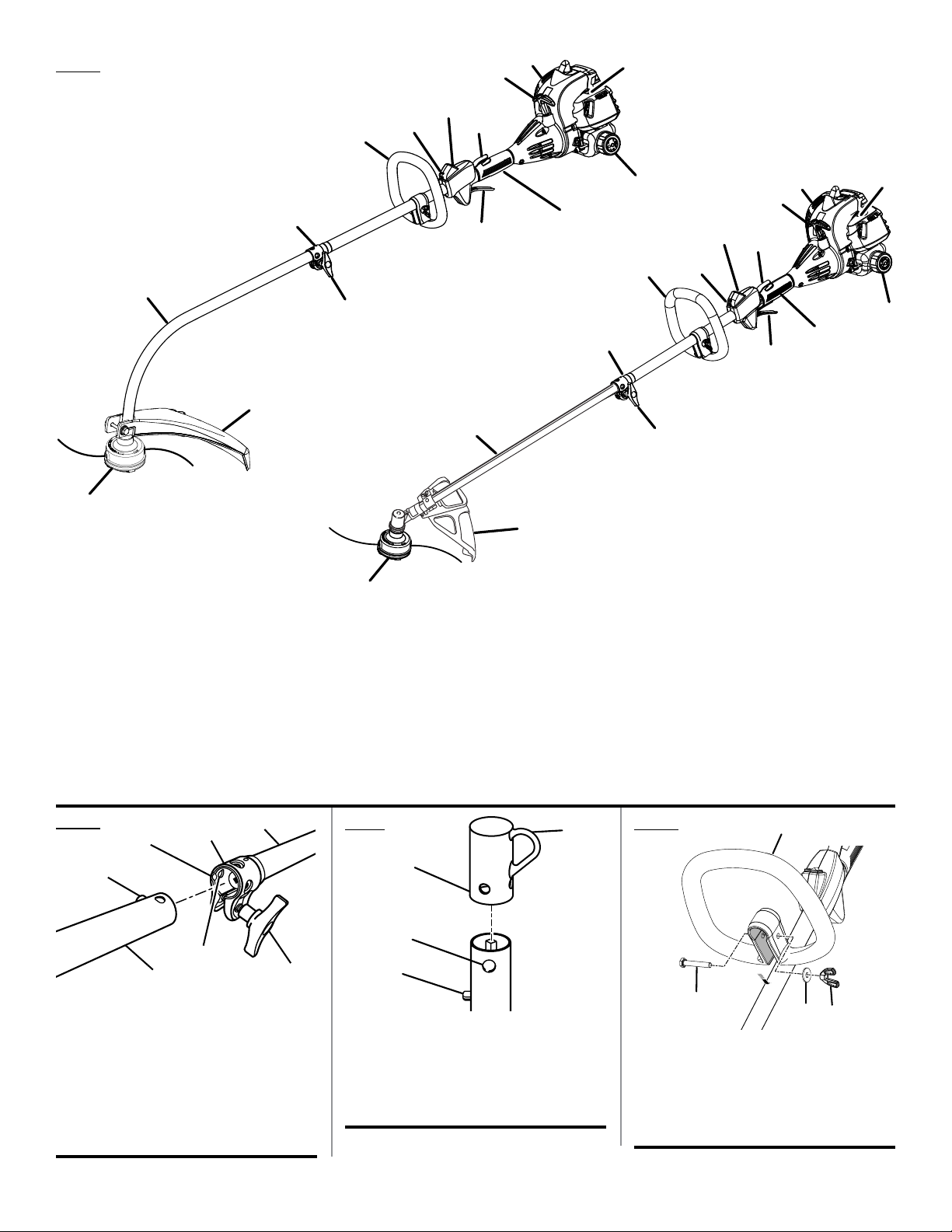
Fig. 1
P
H
I
F
D
E
G
H
J
C
L
K
F
D
E
P
I
H
G
B
M
C
K
J
L
CS26
N
B
A
O
A
M
SS26
A - Reel-Easy™ tap advance string head
(avance de la ligne de coupe à tapant
Reel-Easy™, sistema de avance de hilo por
golpe Reel-Easy™)
B - Drive shaft housing (tube de l’arbre moteur,
alojamiento del eje de impulsión)
C - Coupler (coupleur, acoplador)
D - Front handle (poignée avant, mango
delantero)
E - Strap hanger (dispositif d’accrochage,
colgador para la correa)
Fig. 2
B
C
D
A
F
G
A - Button (bouton, botón)
B - Guide recess (logement guide, hueco guía)
C - Coupler (coupleur, acoplador)
D - Power head shaft (arbre du bloc moteur, eje
del cabezal motor)
E - Knob (bouton, perilla)
F - Positioning hole (trou de positionnement,
orificio de posicionamiento)
G - Trimmer attachment (accessoire taille-
bordures, aditamento para recortar)
E
F - Stop switch (l’interrupteur d’arrêt, interruptor
de parada)
G - Trigger lock-out (verrouillage de gâchette,
seguro del gatillo)
H - Starter grip and rope (poignée du lanceur et
corde, mango del arrancador y cuerda)
I - Primer bulb (poire d’amorçage, bomba de
cebado)
J - Fuel cap (bouchon de carburant, tapa del
tanque)
K - Rear handle (poignée arrière, mango trasero)
Fig.3
D
C
B
A
A - Button (bouton, botón)
B - Secondary hole (trou secondaire, orificio
secundario)
C - Hole (trou, orificio)
D - Hanger cap (capuchon de suspension, tapa
de suspensión)
L - Throttle trigger (gâchette d’accélérateur,
gatillo del acelerador)
M
- Knob (bouton, perilla)
N - Curved shaft grass deflector (déflecteur
d’herbe d’arbre courbe, deflector de pasto del
eje curvo)
O - Straight shaft grass deflector (déflecteur
d’herbe d’arbre droit, deflector de pasto para
eje recto)
P - Muffler (silencieux, silenciador)
Fig. 4
A
A - Bolt (boulon, perno)
B - Front handle (poignée avant, mango
delantero)
C - Washer (rondelle, arandela)
D - Wing nut (écrou papillon, tuerca de
mariposa)
B
C
D
iii
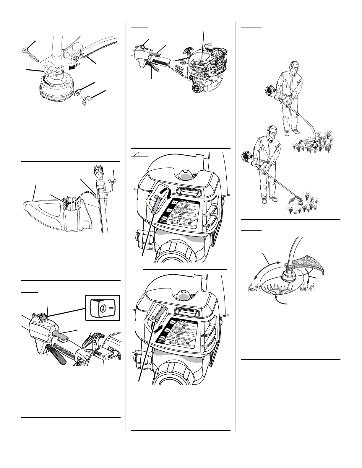
Fig. 5
Fig. 8
A
A
B
C
Fig. 10
PROPER OPERATING POSITION
BONNE POSITION DE TRAVAIL
POSICIÓN CORRECTA PARA EL MANEJO
DE LA HERRAMIENTA
B
E
C
D
A - Bolt (boulon, perno)
B - Bracket (support, placa)
C - Washer (rondelle, arandela)
D - Wing nut (écrou à oreilles, tuerca de
mariposa)
E - Curved shaft grass deflector (déflecteur
d’herbe d’arbre courbe, deflector de pasto
del eje curvo)
Fig. 6
A
C
D
B
A - Straight shaft grass deflector (déflecteur
d’herbe d’arbre droit, deflector de pasto para
eje recto)
B - Slot (fente, ranura)
C - Tab (languette, orejeta)
D - Wing screw (vis à oreilles, tornillo de
mariposa)
D
A - Stop switch (l’interrupteur d’arrêt, interruptor
de parada)
B - Trigger lock-out (verrouillage de gâchette,
seguro del gatillo)
C - Primer bulb (poire d’amorçage, bomba de
cebado)
D - Throttle trigger (gâchette d’accélérateur,
gatillo del acelerador)
Fig. 9
A
Fig. 11
A
B
C
Fig. 7
A
D
B
C
A - Stop switch (l’interrupteur d’arrêt, interruptor
de parada)
B - Trigger lock-out (verrouillage de gâchette,
seguro del gatillo)
C - Throttle trigger (gâchette d’accélérateur,
gatillo del acelerador)
D - Starter grip and rope (poignée du lanceur et
corde, mango del arrancador y cuerda)
D
A - Curved shaft trimmer (taille-bordures à
arbre courbe, recortadora de eje curvo)
B - Dangerous cutting area (zone de coupe
dangereuse, área peligrosa de corte)
C - Direction of rotation (sens de rotation,
sentido de rotación)
D - Best cutting area (zone d’efficacité
maximum, mejor área de corte)
B
A - Choke lever in full choke position (levier de
volet de départ en position ouvert, palanca
del anegador en posición de arranque)
B - Choke lever in run position (levier de volet
de départ en position marche, palanca del
anegador en posición de marcha)
iv
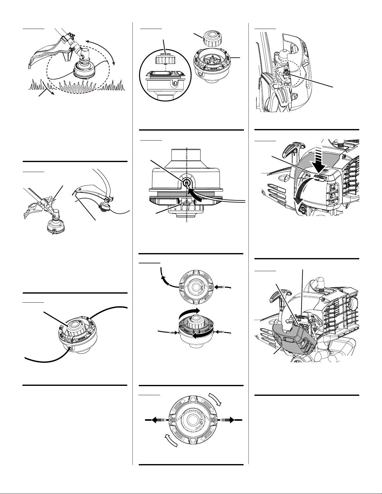
Fig. 12
D
A
Fig. 15
A
A
Fig. 19
B
B
A
C
A - Straight shaft trimmer (taille-bordures à
arbre droit, recortadora de eje recto)
B - Dangerous cutting area (zone de coupe
dangereuse, área peligrosa de corte)
C - Best cutting area (zone d’efficacité maximum,
mejor área de corte)
D - Direction of rotation (sens de rotation,
sentido de rotación)
Fig. 13
A
B
A - Straight shaft trimmer cut-off blade (lame
de sectionnement de ligne du taille-bordures
à arbre droit, cuchilla de corte de hilo de la
recortadora de eje recto)
B - Curved shaft trimmer cut-off blade (lame de
sectionnement de ligne du taille-bordures à
arbre courbe, cuchilla de corte de hilo de la
recortadora de eje recto)
A - Spool retainer (retenue de bobine, retén del
carrete)
B - Spool (bobine, carrete)
Fig. 16
A
B
A - Eyelet (œillet, ojillo)
B - Arrow on spool (flèche sur la bobine, flecha
en el carrete)
Fig. 17
A
A - Idle speed screw (vis de ralenti, tornillo de
marcha lenta)
Fig. 20
A
C
B
A - Latch (loquet, pestillo)
B - Pull cover to open (tirer sur le couvercle
pour l’ouvrir, tire de la tapa para abrirla)
C - Air filter cover (couvercle du filtre à air, tapa
del filtro de aire)
Fig. 21
B
A
Fig. 14
A
A - Spool retainer (retenue de bobine, retén del
carrete)
A - Pull strings (tirer vers l’extérieur, tira del
hilo)
B - Rotate the spool clockwise (tourner le
bobine dans le sens horaire, gire a la derecha
el carrete)
Fig. 18
A
A - Pull strings (tirer vers l’extérieur, tira del
hilo)
v
A
C
A - Latch (loquet, pestillo)
B - Filter screen (filtre écran, filtro pantalla)
C - Air filter cover (couvercle du filtre à air, tapa
del filtro de aire)

TABLE OF CONTENTS
TABLE DES MATIÈRES / ÍNDICE DE CONTENIDO
Introduction ......................................................................................................................................................................2
Introduction / Introducción
General Safety Rules ..................................................................................................................................................... 3-4
Règles de sécurité générales / Reglas de seguridad generales
Specific Safety Rules ........................................................................................................................................................ 4
Règles de sécurité particulières / Reglas de seguridad específicas
Symbols ............................................................................................................................................................................ 5
Symboles / Símbolos
Features ............................................................................................................................................................................6
Caractéristiques / Características
Assembly .......................................................................................................................................................................6-8
Assemblage / Armado
Operation .....................................................................................................................................................................8-10
Utilisation / Funcionamiento
Maintenance ..............................................................................................................................................................11-13
Entretien / Mantenimiento
Troubleshooting .............................................................................................................................................................. 14
Dépannage / Solución de problemas
Warranty ....................................................................................................................................................................15-16
Garantie / Garantía
Parts Ordering and Service ...............................................................................................................................Back Page
Commande de pièces et réparation / Pedidos de piezas y servicio ......................................................... Page arrière / Pág. posterior
INTRODUCTION
INTRODUCTION / INTRODUCCIÓN
This product has many features for making its use more pleasant and enjoyable. Safety, performance, and dependability
have been given top priority in the design of this product making it easy to maintain and operate.
* * *
Ce produit offre de nombreuses fonctions destinées à rendre son utilisation plus plaisante et satisfaisante. Lors de la
conception de ce produit, l’accent a été mis sur la sécurité, les performances et la fiabilité, afin d’en faire un outil facile à
utiliser et à entretenir.
* * *
Este producto ofrece numerosas características para hacer más agradable y placentero su uso. En el diseño de este producto
se ha conferido prioridad a la seguridad, el desempeño y la fiabilidad, por lo cual se facilita su manejo y mantenimiento.
2

GENERAL SAFETY RULES
WARNING:
Read and understand all instructions. Failure to follow all
instructions listed below may result in electric shock, fire
and/or serious personal injury.
READ ALL INSTRUCTIONS
For safe operation, read and understand all instructions
before using this product. Follow all safety instructions.
Failure to follow all safety instructions listed below, can
result in serious personal injury.
Do not allow children or untrained individuals to use this
unit.
Do not start or operate the engine in a confined space,
building, near open windows, or in other unventilated
space where dangerous carbon monoxide fumes can
collect. Carbon monoxide, a colorless, odorless, and
extremely dangerous gas, can cause unconsciousness
or death.
Clear the work area before each use. Remove all objects
such as rocks, broken glass, nails, wire, or loose string
which can be thrown or become entangled in the cutting
line or blade.
Always wear eye protection with side shields marked to
comply with ANSI Z87.1 along with hearing protection
when operating this equipment.
Wear heavy, long pants, long sleeves, boots, and gloves.
Do not wear loose fitting clothing, short pants, sandals,
or go barefoot. Do not wear jewelry of any kind.
Heavy protective clothing may increase operator fatigue,
which could lead to heat stroke. During weather that is
hot and humid, heavy work should be scheduled for early
morning or late afternoon hours when temperatures are
cooler.
Product users on United States Forest Service land, and in
some states, must comply with fire prevention regulations.
This product is equipped with a spark arrestor; however,
other user requirements may apply. Check with your
federal, state, or local authorities.
Never operate this unit on the operator’s left side.
Secure long hair above shoulder level to prevent
entanglement in moving parts.
Keep all bystanders, children, and pets at least
50 ft. away. Bystanders should be encouraged to wear
eye protection. If you are approached, stop the engine
and cutting attachment. In the case of bladed units, there
is the added risk of injury to bystanders from being struck
with the moving blade in the event of a blade thrust or
other unexpected reaction of the saw.
Do not operate this unit when you are tired, ill, upset, or
under the influence of alcohol, drugs, or medication.
Do not operate in poor lighting.
Keep firm footing and balance. Do not overreach.
Overreaching can result in loss of balance or exposure
to hot surfaces.
Keep all parts of your body away from any moving part.
To avoid hot surfaces, never operate the unit with the
bottom of the engine above waist level.
Do not touch area around the muffler or cylinder of the
unit, these parts get hot from operation. Contact with hot
surfaces could result in possible serious personal injury.
Always stop the engine and remove the spark plug wire
before making any adjustments or repairs except for
carburetor adjustments.
Inspect the unit before each use for loose fasteners, fuel
leaks, etc. Replace any damaged parts before use.
The cutting attachment should never rotate at idle during
normal use. The cutting attachment may rotate at idle
during carburetor adjustments.
It has been reported that vibrations from hand-held tools
may contribute to a condition called Raynaud’s Syndrome
in certain individuals. Symptoms may include tingling,
numbness, and blanching of the fingers, usually apparent
upon exposure to cold. Hereditary factors, exposure to
cold and dampness, diet, smoking, and work practices
are all thought to contribute to the development of these
symptoms. It is presently unknown what, if any, vibrations
or extent of exposure may contribute to the condition.
There are measures that can be taken by the operator to
possibly reduce the effects of vibration:
a) Keep your body warm in cold weather. When operating
the unit wear gloves to keep hands and wrists warm.
It is reported that cold weather is a major factor contributing to Raynaud’s Syndrome.
b) After each period of operation, exercise to increase
blood circulation.
c) Take frequent work breaks. Limit the amount of
exposure per day.
d) Keep the tool well maintained, fasteners tightened,
and worn parts replaced.
If you experience any of the symptoms of this condition,
immediately discontinue use and see your physician about
these symptoms.
Mix and store fuel in a container approved for gasoline.
Mix fuel outdoors where there are no sparks or flames.
Wipe up any fuel spillage. Move 30 ft. away from refueling
site before starting engine. Slowly remove the fuel cap
after stopping engine. Do not smoke when refueling.
3 — English

GENERAL SAFETY RULES
Stop the engine and allow to cool before refueling or
storing the unit.
Allow the engine to cool; empty the fuel tank and secure
the unit from moving before transporting in a vehicle.
SPECIFIC SAFETY RULES
SPECIFIC SAFETY RULES FOR TRIMMER
USE
Inspect before use. Replace damaged parts. Make sure
fasteners are in place and secure. Check for fuel leaks.
Replace string head if cracked, chipped, or damaged
in any way. Be sure the string head or blade is properly
installed and securely fastened. Failure to do so can cause
serious injury.
Make sure all guards, straps, deflectors, and handles are
properly and securely attached.
Never use blades, flailing devices, wire, or rope. Use only
identical replacement line in the cutting head. Do not use
any other cutting attachment. To install any other brand
of cutting head to this string trimmer can result in serious
personal injury.
Wear your protective equipment and observe all safety
instructions. For units equipped with a clutch, be sure
the cutting attachment stops turning when the engine
idles. When the unit is turned off make sure the cutting
attachment has stopped before the unit is set down.
Never operate unit without the grass deflector in place
and in good condition.
Maintain a firm grip on both handles while trimming. Keep
string head below waist level. Never cut with the string
head located over 30 in. or more above the ground.
This product is intended for infrequent use by homeown-
ers and other occasional users for such general applications as trimming light and heavy vegetation, etc. It is not
intended for prolonged use. Prolonged periods of operation can cause circulatory problems in the user’s hands
due to vibration. For such use, it may be appropriate to
use a product having an anti-vibration feature.
4 — English

SYMBOLS
The following signal words and meanings are intended to explain the levels of risk associated with this product.
SYMBOL SIGNAL MEANING
DANGER:
WARNING:
CAUTION:
NOTICE:
Some of the following symbols may be used on this product. Please study them and learn their meaning for safe
operation of this product.
SYMBOL NAME EXPLANATION
Safety Alert Indicates a potential personal injury hazard.
Read Operator’s Manual
Indicates an imminently hazardous situation, which, if not avoided, will result
in death or serious injury.
Indicates a potentially hazardous situation, which, if not avoided, could result
in death or serious injury.
Indicates a potentially hazardous situation, which, if not avoided, may result in
minor or moderate injury.
(Without Safety Alert Symbol) Indicates important information not related to an
injury hazard, such as a situation that may result in property damage.
To reduce the risk of injury, user must read and understand operator’s manual before using this product.
Always wear eye protection with side shields marked to
Eye and Hearing Protection
Keep Bystanders Away Keep all bystanders at least 50 ft. away.
Ricochet
No Blade
Gasoline and Lubricant
comply with ANSI Z87.1 along with hearing protection
when operating this equipment.
Thrown objects can ricochet and result in personal injury
or property damage.
Do not install or use any type of blade on a product displaying this symbol.
Use unleaded gasoline intended for motor vehicle use
with an octane rating of 87 [(R + M) / 2] or higher. This
product is powered by a 2-cycle engine and requires
pre-mixing gasoline and 2-cycle lubricant.
5 — English

FEATURES
PRODUCT SPECIFICATIONS
Weight - (without fuel)
CS26 ...................................................................................................................................................................10.3 lbs.
SS26 ...................................................................................................................................................................11.8 lbs.
Line cutting width
CS26 ........................................................................................................................................................................17 in.
SS26 ........................................................................................................................................................................18 in.
Engine displacement ....................................................................................................................................................26cc
Line diameter ...........................................................................................................................................................0.095 in.
KNOW YOUR PRODUCT
See Figure 1.
The safe use of this product requires an understanding of
the information on the tool and in this operator’s manual as
well as a knowledge of the project you are attempting. Before
use of this product, familiarize yourself with all operating
features and safety rules.
GRASS DEFLECTOR
The product includes a grass deflector that helps protect
you from flying debris.
ASSEMBLY
UNPACKING
This product requires assembly.
Carefully remove the items from the box. Make sure that
all items listed in the packing list are included.
WARNING:
Do not use this product if any parts on the packing list are
already assembled to your product when you unpack it.
Parts on this list are not assembled to the product by the
manufacturer and require customer installation. Use of a
product that may have been improperly assembled could
result in serious personal injury.
Inspect the unit carefully to make sure no damage
occurred during shipping.
Do not discard the packing material until you have carefully
inspected and satisfactorily operated the product.
If any parts are damaged or missing, please call
1-800-860-4050 for assistance.
REEL-EASY™ TAP ADVANCE SYSTEM
The Reel-Easy™ Tap Advance System allows easy line
advance during trimmer operation.
TOP-MOUNTED MOTOR
The top-mounted motor improves balance and is located
away from the dust and debris of the cutting area.
PACKING LIST
CS26
Trimmer Assembly
Front Handle
Curved Shaft Grass Deflector
Bottle of 2-Cycle Lubricant
Operator’s Manual
SS26
Trimmer Assembly
Front Handle
Straight Shaft Grass Deflector
Bottle of 2-Cycle Lubricant
Operator’s Manual
6 — English

ASSEMBLY
WARNING:
If any parts are damaged or missing do not operate this
product until the parts are replaced. Use of this product
with damaged or missing parts could result in serious
personal injury.
WARNING:
Do not attempt to modify this product or create accessories not recommended for use with this product. Any
such alteration or modification is misuse and could result
in a hazardous condition leading to possible serious
personal injury.
WARNING:
To prevent accidental starting that could cause serious
personal injury, always disconnect the engine spark plug
wire from the spark plug when assembling parts.
INSTALLING THE POWER HEAD TO THE
ATTACHMENT
See Figure 2.
WARNING:
Never install, remove, or adjust any attachment while
power head is running. Failure to stop the engine can
cause serious personal injury.
REMOVING THE ATTACHMENT FROM THE
POWER HEAD
For removing or changing the attachment:
Loosen the knob.
Push in the button and twist the shafts to remove and
separate ends.
ATTACHING THE STORAGE HANGER
See Figure 3.
There are two ways to hang your attachment for storage.
To use the hanger cap, push in the button and place
the hanger cap over end of trimmer attachment. Slightly
rotate the cap from side to side until the button locks into
place.
The secondary hole in the trimmer attachment can be
used for hanging purposes as well.
ATTACHING THE FRONT HANDLE
See Figure 4.
Remove wing nut, washer, and bolt from the front handle.
Install the front handle onto the top side of the drive shaft
housing in the area indicated by the label.
NOTE: The open side of the handle should face the
operator.
Place the bolt through the front handle.
NOTE: The hex bolt head fits inside the hex recess molded
into one side of the handle.
Reinstall the washer and wing nut.
Tighten wing nut securely.
The attachment connects to the power head by means of
a coupler device.
Loosen the knob on the coupler of the power head shaft
and remove the hanger cap from the attachment.
Push in the button located on the trimmer attachment.
Align the button with the guide recess on the power
head coupler and slide the two shafts together. Rotate
the trimmer attachment until the button locks into the
positioning hole.
NOTE: If the button does not release completely in the
positioning hole, the shafts are not locked into place.
Slightly rotate from side to side until the button is locked
into place.
Tighten the knob securely.
WARNING:
Be certain the knob is fully tightened before operating
equipment; check it periodically for tightness during use
to avoid serious personal injury.
7 — English
ATTACHING THE GRASS DEFLECTOR
WARNING:
The line cutting blade on the grass deflector is sharp.
Avoid contact with the blade. Failure to avoid contact
can result in serious personal injury.
TO ATTACH THE CURVED SHAFT GRASS
DEFLECTOR - CS26
See Figure 5.
Remove hex screw, washer, and wing nut from grass
deflector.
Press the grass deflector onto the bottom of the curved
shaft as shown.
Insert the hex screw through the grass deflector and the
bracket on the curved shaft.
Place the washer on the hex screw.
Place the wing nut on the hex screw and tighten
securely.

ASSEMBLY
TO ATTACH THE STRAIGHT SHAFT GRASS
DEFLECTOR - SS26
See Figure 6.
Remove the wing screw from the grass deflector.
Insert the tab on the mounting bracket in the slot on the
grass deflector.
OPERATION
WARNING:
Do not allow familiarity with this product to make you
careless. Remember that a careless fraction of a second is
sufficient to inflict serious injury.
WARNING:
Always wear eye protection with side shields marked to
comply with ANSI Z87.1, along with hearing protection.
Failure to do so could result in objects being thrown into
your eyes and other possible serious injuries.
WARNING:
Never use blades, flailing devices, wire, or rope on this
product. Do not use any attachments or accessories not
recommended by the manufacturer of this product. The
use of attachments or accessories not recommended
can result in serious personal injury.
Align the screw hole in the mounting bracket with the
screw hole in the grass deflector.
Insert the wing screw through the mounting bracket and
into the grass deflector.
Tighten the screw securely.
FUELING AND REFUELING THE TRIMMER
FUEL MIXTURE
This product is powered by a 2-cycle engine and requires
pre-mixing gasoline and 2-cycle lubricant. Pre-mix unleaded
gasoline and 2-cycle engine lubricant in a clean container
approved for gasoline. DO NOT mix quantities larger than
usable in a 30-day period.
Recommended fuel: This engine is certified to operate on
unleaded gasoline intended for automotive use.
NOTE: We recommend you use Homelite premium 2-cycle
lubricant, PowerCare 2-cycle lubricant (6.4 oz. or 16 oz.), or
an equivalent high-quality synthetic 2-cycle lubricant in this
product. Mix at 2.6 oz. per gallon (US).
Do not use automotive lubricant or 2-cycle outboard
lubricant.
HIGH QUALITY 2-CYCLE ENGINE LUBRICANT
GASOLINE LUBRICANT
1.0 gal. (US) (3.8 liter) 2.6 oz. (76 ml)
2.5 gal. (US) (9.5 liter) 6.4 oz. (189 ml)
WARNING:
Operation of this equipment may create sparks that
can start fires around dry vegetation. A spark arrestor
may be required. The operator should contact local fire
agencies for laws or regulations relating to fire prevention
requirements.
WARNING:
Gasoline and its vapors are highly flammable and explosive. To prevent serious personal injury and property
damage, handle it with care. Keep away from ignition
sources and open flames, handle outdoors only, do not
smoke and wipe up spills immediately.
8 — English
FILLING TANK
Clean surface around fuel cap to prevent contamination.
Loosen fuel cap slowly. Rest the cap on a clean surface.
Carefully pour fuel into the tank. Avoid spillage.
Prior to replacing the fuel cap, clean and inspect the
gasket.
Immediately replace fuel cap and hand tighten. Wipe up
any fuel spillage.
NOTE: It is normal for smoke to be emitted from a new
engine after first use.
WARNING:
Always shut off engine before fueling. Never add fuel to
a machine with a running or hot engine. Move at least
30 ft. from refueling site before starting engine. Do not
smoke! Failure to safely handle fuel could result in serious personal injury.

OPERATION
OXYGENATED FUELS
NOTICE:
Do not use E15 or E85 fuel (or fuel containing greater
than 10% ethanol) in this product. It is a violation of
federal law and will damage the unit and void your
warranty.
Fuel system damage or performance problems resulting
from the use of an oxygenated fuel containing more than
the percentage of oxygenates stated below are not covered
under warranty.
Ethanol. Gasoline containing up to 10% ethanol by volume
(commonly referred to as E10) is acceptable. E15 and E85
are not.
STARTING AND STOPPING
See Figures 7 - 9.
Trimmer should be on a flat, bare surface for starting.
To start a cold engine:
Slowly press the primer bulb 10 times.
NOTE: After the 7th press, fuel should be visible in the
primer bulb. If it is not, continue to press the primer until
you see fuel in the bulb.
Set the choke lever to the FULL CHOKE position.
Squeeze the throttle trigger fully and pull starter grip and
rope sharply until engine attempts to run. Do not pull the
starter grip and rope more than four (4) times.
NOTE: Keep throttle trigger squeezed fully.
Set the choke lever to the HALF CHOKE position.
Pull the starter grip and rope until the engine runs. Do not
pull the starter grip and rope more than six (6) times.
NOTE: If the engine does not start, return to the FULL
CHOKE position and repeat the steps that follow.
Allow the engine to run for 10 seconds, then set the choke
lever to the RUN position.
To restart a warm engine:
Slowly press the primer bulb 10 times.
Set the choke lever to the RUN position.
Squeeze the throttle trigger fully and pull the starter grip
and rope until the engine runs.
To stop the engine:
To stop the engine, depress the STOP switch to the stop
position “
IF ASSISTANCE IS REQUIRED FOR THIS PRODUCT:
Do not return this product to the retail store where it was
purchased. Please call our Customer Service Department
for any issues you may have.
For Help Call: 1-800-860-4050
”.
OPERATING THE TRIMMER
See Figure 10.
WARNING:
Engine housing may become hot during trimmer operation. Do not rest or place your arm, hand, or any body
part against the engine housing during trimmer operation.
Only hold the trimmer as shown in Figure 10 with all body
parts clear of engine housing. Extended contact with the
engine housing can result in burns or other injuries.
WARNING:
Always position the unit on the operator’s right side. The
use of the unit on the operator’s left side will expose the
user to hot surfaces and can result in possible burn injury.
WARNING:
To avoid burns from hot surfaces, never operate unit with
the bottom of the engine above waist level.
Hold the trimmer with your right hand on the rear handle
and your left hand on the front handle. Keep a firm grip with
both hands while in operation. Trimmer should be held at a
comfortable position with the rear handle about hip height.
Always operate trimmer in RUN position. Cut tall grass
from the top down. This will prevent grass from wrapping
around the shaft housing and string head which could cause
damage from overheating. If grass becomes wrapped around
the string head, STOP THE ENGINE, disconnect the spark
plug wire, and remove the grass. Prolonged cutting at partial
throttle will result in lubricant dripping from the muffler.
WARNING:
Always hold the string trimmer away from the body keeping clearance between the body and the product. Any
contact with the housing or string trimmer cutting head
can result in burns and/or other serious personal injury.
CUTTING TIPS
See Figures 10 - 12.
Avoid hot surfaces by always keeping the tool away from
your body. (Proper operating position shown in figure 10.)
Keep the trimmer tilted toward the area being cut; this is
the best cutting area.
The curved shaft trimmer cuts when passing the unit from
right to left. The straight shaft trimmer cuts when passing
the unit from left to right. This will avoid throwing debris at
the operator. Avoid cutting in the dangerous area shown
in illustration.
9 — English

OPERATION
Use the tip of line to do the cutting; do not force string
head into uncut grass.
Wire and picket fences cause extra line wear, even
breakage. Stone and brick walls, curbs, and wood may
wear line rapidly.
Avoid trees and shrubs. Tree bark, wood moldings, siding,
and fence posts can easily be damaged by the line.
ADVANCING STRING USING THE REEL-EASY™
TAP ADVANCE SYSTEM
String advance is controlled by tapping the string head’s
spool retainer on grass while running engine at full throttle.
Run engine at full throttle.
Tap string head on ground to advance string. String
advances each time the head is tapped.
Several taps may be required until string strikes the cut
off blade.
Resume trimming.
NOTE: If the string is worn too short you may not be able to
advance the string by tapping it on the ground. If so, STOP
THE ENGINE, disconnect the spark plug wire, and manually
advance the string.
ADVANCING THE STRING MANUALLY
With the engine off and the spark plug wire disconnected,
push the spool retainer down while pulling on string(s) to
manually advance the string.
GRASS DEFLECTOR LINE TRIMMING CUT-OFF
BLADE
See Figure 13.
The trimmer is equipped with a line trimming cut-off blade on
the grass deflector. For best cutting, advance line until it is
trimmed to length by the cut-off blade. Advance the line whenever you hear the engine running faster than normal, or when
trimming efficiency diminishes. This will maintain best performance and keep the line long enough to advance properly.
10 — English

MAINTENANCE
WARNING:
When servicing, use only identical replacement parts.
Use of any other parts could create a hazard or cause
product damage.
WARNING:
Always wear eye protection with side shields marked to
comply with ANSI Z87.1, along with hearing protection.
Failure to do so could result in objects being thrown into
your eyes and other possible serious injuries.
WARNING:
Before inspecting, cleaning, or servicing the machine,
shut off engine, wait for all moving parts to stop, and
disconnect spark plug wire and move it away from spark
plug. Failure to follow these instructions can result in
serious personal injury or property damage.
GENERAL MAINTENANCE
Avoid using solvents when cleaning plastic parts. Most
plastics are susceptible to damage from various types of
commercial solvents and may be damaged by their use.
Use clean cloths to remove dirt, dust, lubricant, grease, etc.
WARNING:
Do not at any time let brake fluids, gasoline, petroleumbased products, penetrating lubricants, etc., come in contact with plastic parts. Chemicals can damage, weaken or
destroy plastic which may result in serious personal injury.
You can often make adjustments and repairs described here.
For other repairs, have the trimmer serviced by an authorized
service dealer.
SPOOL REPLACEMENT
REEL-EASY™ TAP ADVANCE SYSTEM
See Figures 14 - 16.
If replacing line only, refer to Line Replacement later in
this manual.
Use only .095 in. trimmer line.
Stop the engine and disconnect the spark plug wire. Hold
the string head and unscrew the spool retainer.
To remove the spool retainer:
Turn the spool retainer counterclockwise for CS26.
Turn the spool retainer clockwise for SS26.
Remove the empty spool from the string head.
NOTE: It is not necessary to remove the string head
housing from the drive shaft.
Insert the new spool into the string head.
NOTE: Make sure the arrows on the spool are aligned
with the eyelets in the string head housing. Push down
and hold the spool and housing together while complet-
ing the installation.
Reinstall the spool retainer to secure.
To install the spool retainer:
Turn the spool retainer clockwise for CS26.
Turn the spool retainer counterclockwise for SS26.
Install line as described in LINE REPLACEMENT.
LINE REPLACEMENT
See Figures 16 - 18.
Stop the engine and disconnect the spark plug wire.
Rotate the spool clockwise as necessary to align the arrows
on the spool with the eyelets in the string head housing.
Cut one piece of trimmer line 10 ft. long. Insert the line
into the eyelet on the string trimmer housing. Push until
the end of the line comes out the other side of the string
head. Pull the line from the other side until equal amounts
of line appear on both sides of the spool.
Rotate the spool clockwise to wind the line on the spool
until approximately 6 in. of line is showing on each side.
Push the spool retainer down while pulling on line(s) to
manually advance the line and to check for proper as-
sembly of the string head.
CLEANING THE EXHAUST PORT, MUFFLER,
AND SPARK ARRESTOR
NOTE: Depending on the type of fuel used, the type and
amount of lubricant used, and/or your operating conditions, the
exhaust port, muffler, and/or spark arrestor screen may become blocked with carbon deposits. If you notice a power
loss with your gas powered tool, you may need to remove
these deposits to restore performance. We highly recommend that only qualified service technicians perform this
service.
The spark arrestor must be cleaned or replaced every 50
hours or yearly to ensure proper performance of your product. Spark arrestors may be in different locations depending
on the model purchased. Please contact your nearest service
dealer for the location of the spark arrestor for your model.
11 — English

MAINTENANCE
IDLE SPEED ADJUSTMENT
See Figure 19.
WARNING:
The cutting head will move when adjusting the idle speed.
Wear all protective clothing and keep all bystanders,
children, and pets at least 50 ft. away. Make adjustments
with the unit supported by hand so that the blade/cutting
head does not contact the ground or any object. Keep
all parts of your body away from the cutting head and
muffler. Failure to follow these instructions could result
in serious personal injury.
If the cutting attachment turns at idle, the idle speed screw
needs adjusting on the engine. Turn the idle speed screw
counterclockwise to reduce the idle RPM and stop the cutting attachment movement. If the cutting attachment still
moves at idle speed, contact a service dealer for adjustment
and discontinue use until the repair is made.
WARNING:
The cutting attachment should never turn at idle. Turn
the idle speed screw counterclockwise to reduce the
idle RPM and stop the cutting attachment, or contact a
service dealer for adjustment and discontinue use until
the repair is made. Serious personal injury could result
from the cutting attachment turning at idle.
CLEANING AIR FILTER SCREEN
See Figures 20 - 21.
For proper performance and long life, keep air filter screen
clean.
Remove the air filter cover by pushing down on the latch
with your thumb while gently pulling on the cover.
Brush the air filter screen lightly to clean.
Replace the air filter cover by inserting the tabs on the
bottom of the cover into the slots on the air filter base;
push the cover up until it latches securely in place.
FUEL CAP, TANK, AND LINES
WARNING:
Check for fuel leaks. A leaking fuel cap, tank, or lines
are a fire hazard and must be replaced immediately. If
you find any leaks, correct the problem before using the
product. Failure to do so could result in a fire that could
cause serious personal injury.
The fuel cap contains a non-serviceable filter and a check
valve. A clogged fuel filter will cause poor engine performance. If performance improves when the fuel cap is
loosened, the check valve may be faulty or filter clogged.
Replace the fuel cap if required.
SPARK PLUG REPLACEMENT
The spark plug for this engine may be replaced using a Ryobi
accessory spark plug or a Champion RCJ6Y. The spark plug
gap should be set at .025 in. Use an exact replacement and
replace annually.
STORING THE PRODUCT
Clean all foreign material from the product. Store idle unit
indoors in a dry, well-ventilated area that is inaccessible
to children. Keep away from corrosive agents such as
garden chemicals and de-icing salts.
Abide by all ISO and local regulations for the safe storage
and handling of gasoline.
When storing 1 month or longer:
Drain all fuel from tank into a container approved for
gasoline. Run engine until it stops.
HIGH ALTITUDE ENGINE OPERATION
Please have an authorized service center adjust this engine
if it is to be run above 2000 feet. Failure to do so may result
in poor engine performance and increased emissions. An
engine adjusted for high altitudes can not be run at 2000
feet or lower. In doing so, the engine will overheat and cause
serious engine damage. Please have an authorized service
center restore high altitude modified engines to the original
factory specification before operating below 2000 feet.
12 — English
 Loading...