


RY29550
OPERATOR’S MANUAL
MANUEL D’UTILISATION
MANUAL DEL OPERADOR
30CC STRING TRIMMER
ELECTRIC START
TAILLE-BORDURES DE 30 cc
DÉMARRAGE ÉLECTRIQUE
RECORTADORAS DE HILO 30 cc
ARRANQUE ELÉCTRICO
RY29550
ALL VERSIONS
TOUTES LES VERSIONS
TODAS LAS VERSIONES
Le taille-bordures à ligne a été conçue et fabriquée conformément
à nos strictes normes de fiabilité, simplicité d’emploi et sécurité
d’utilisation. Correctement entretenue, elle vous donnera des
années de fonctionnement robuste et sans problème.
AVERTISSEMENT : Pour réduire les risques de
blessures, l’utilisateur doit lire et veiller à bien comprendre le
manuel d’utilisation avant d’employer ce produit.
Merci de votre achat.
Su recortadoras de hilo ha sido diseñada y fabricada de conformidad
con las estrictas normas para brindar fiabilidad, facilidad de uso
y seguridad para el operador. Con el debido cuidado, le brindará
muchos años de sólido y eficiente funcionamiento.
ADVERTENCIA: Para reducir el riesgo de lesiones,
el usuario debe leer y comprender el manual del operador antes
de usar este producto.
Le agradecemos su compra.
CONSERVER CE MANUEL POUR
FUTURE RÉFÉRENCE
GUARDE ESTE MANUAL PARA
FUTURAS CONSULTAS
SAVE THIS MANUAL FOR FUTURE REFERENCE
Your trimmer has been engineered and manufactured to our high standard for dependability, ease of operation, and opera-
tor safety. When properly cared for, it will give you years of rugged, trouble-free performance.
WARNING: To reduce the risk of injury, the user must read and understand the operator’s manual before using
this product.
Thank you for your purchase.
ii
Fig. 1
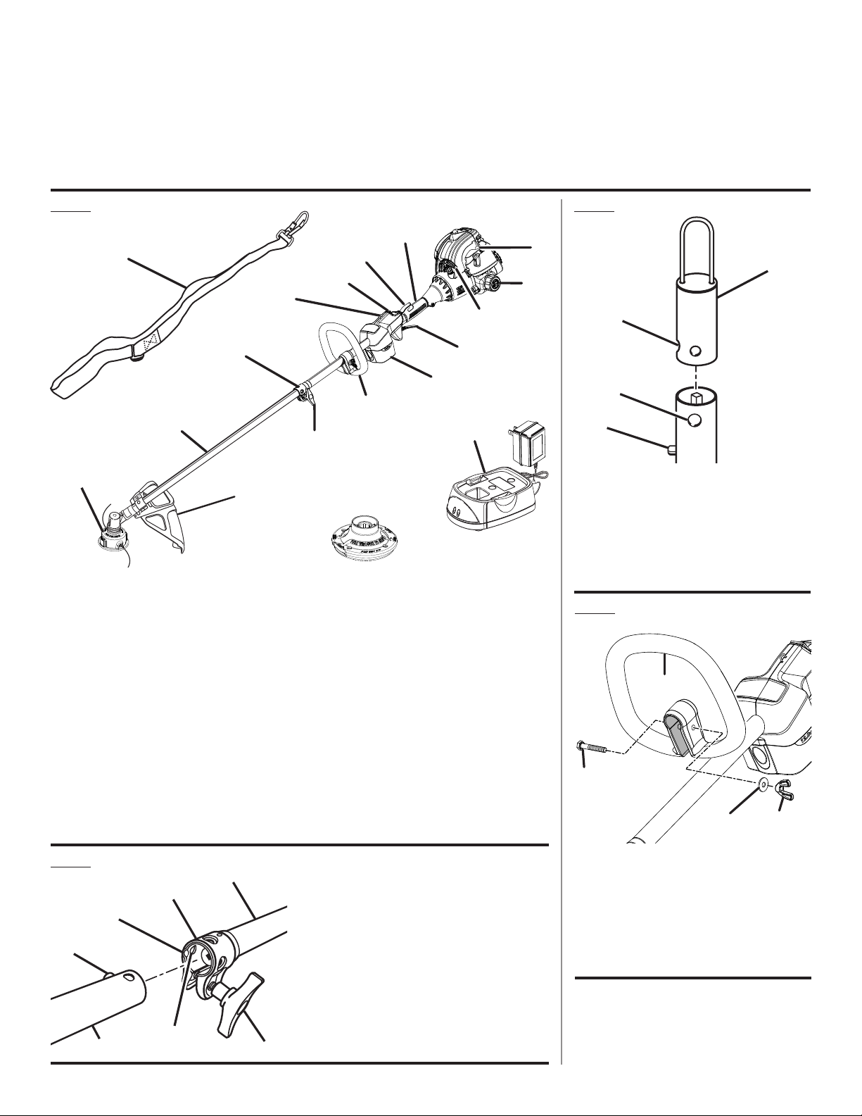
A - Shoulder strap (bandoulière, correa para el
hombro)
B - Rear handle (poignée arrière, mango trasero)
C - Trigger lock (verrouillage de gâchette, seguro
del gatillo)
D- Ignition switch (commutateur d’allumage,
interruptor de encendido)
E - Strap hanger (dispositif d’accrochage,
colgador para la correa)
F - Coupler (coupleur, acoplador)
G - Drive shaft (tube de l’arbre moteur, alojamiento
del eje de impulsión)
H
- Reel Easy
TM
string head (tête à ligne de
coupe de Reel Easy
TM
, cabezal del hilo
Reel Easy
TM
)
I - Grass deflector (déflecteur d’herbe, deflector
de pasto)
Fig. 3
Fig. 4
A - Front handle (poignée avant, mango
delantero)
B - Bolt (boulon, perno)
C - Washer (rondelle, arandela)
D - Wing nut (écrou à oreilles, tuerca de
mariposa)
Fig. 2
A - Hanger cap (capuchon de suspension, tapa
de suspensión)
B - Hole (trou, orificio)
C - Secondary hole (trou secondaire, orificio
secundario)
D - Button (bouton, botón)
J - Pro Cut II
TM
string head (tête à ligne de coupe
de Pro Cut II
TM
, cabezal del hilo Pro Cut II
TM
)
K - Knob (bouton, perilla)
L - Front handle (poignée avant, mango
delantero)
M - 12 volt battery (bloc de batteries de 12 v,
paquete de baterías de 12 v)
N - Throttle trigger (gâchette d’accélérateur,
gatillo del acelerador)
O - Recoil starter (poignée et cordon du lanceur,
mango y cuerda del arrancador)
P - Fuel cap (bouchon de carburant, tapa del
tanque)
Q - Primer bulb (poire d’amorçage, bomba de
cebado)
R - Charger (chargeur, cargador)
See this fold-out section for all of the figures
referenced in the operator’s manual.
Consulter l’encart à volets afin d’examiner toutes les figures
mentionnées dans le manuel d’utilisation.
Consulte esta sección desplegable para ver todas las figuras
a las que se hace referencia en el manual del operador.
N
L
F
G
H
I
K
B
O
Q
C
P
D
E
R
J
A
M
B
G
E
A
F
C
D
A - Power head shaft (arbre du bloc moteur, eje
de la cabezal motor)
B - Coupler (accouplement, acoplador)
C - Guide recess (logement guide, hueco guía)
D - Button (bouton, botón)
E - Trimmer attachment (accessoire taille-
bordures, aditamento para recortar)
F - Positioning hole (trou de positionnement,
orificio de posicionamiento)
G - Knob (bouton, perilla)
D
B
A
C
D
A
B
C

iii
Fig. 7
Fig. 8
Fig. 6
A - Battery port (logement de la batterie,
receptáculo para baterías)
B - Latches (loquets, pestillos)
C - Battery (batterie, batería)
Fig. 9
A - Dangerous cutting area (zone de coupe
dangereuse, área peligrosa de corte)
B - Direction of rotation (sens de rotation, sentido
de rotación)
C - Best cutting area (zone d’efficacité maximum,
mejor área de corte)
B
A
C
A - Latch (attache, pestillo)
B - Strap (bandoulière, correa)
C - Hanger bracket (support pendant, soporte del
colgador)
BATTERY SHOWN IN CHARGER /
BLOC DE BATTERIES DANS LE CHARGEUR
/ PILA VISTA EN EL CARGADOR
A
B
C
A
DEPRESS LATCHES TO RELEASE
BATTERY PACK / APPUYER SUR LES
LOQUETS POUR LIBÉRER LE BLOC DE
BATTERIES / PARA SOLTAR EL PAQUETE
DE PILAS OPRIMA LOS PESTILLOS
B
A - Red LED (témoin rouge, diodo rojo)
B - Orange LED (témoin orange, diodo naranja)
PROPER OPERATING POSITION /
BONNE POSITION DE TRAVAIL /
POSICIóN CORRECTA PARA EL MANEJO
DE LA HERRAMIENTA
C
A
B
A
Fig. 10
Fig. 11
A - Trimmer string cut-off blade (lame de
sectionnement de ligne du taille-bordures,
cuchilla de corte de hilo de la recortadora)
Fig. 12
B
A
C
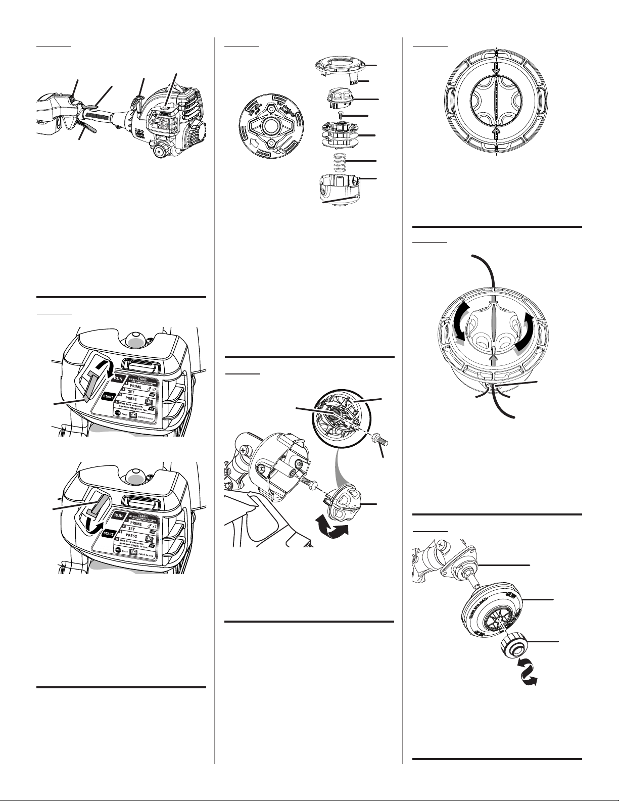
A - Ignition switch (interrupteur d’allumage,
interruptor de encendido)
B - Throttle trigger (gâchette d’accélérateur,
gatillo del acelerador)
C - Trigger lock (verrouillage de gâchette, seguro
del gatillo)
Fig. 5
A - Grass deflector (déflecteur d’herbe, deflector
de pasto)
B - Slot (fente, ranura)
C - Tab (languette, orejeta)
D - Wing screw (vis à oreilles, tornillo de
mariposa)
D
A
C
B
iv
Fig. 14
Fig. 13
E
A
D
A
B
D
C
B
C
A - Ignition switch (interrupteur d’allumage,
interruptor de encendido)
B - Trigger lock (verrouillage de gâchette, seguro
del gatillo)
C - Recoil starter (cordon du lanceur, cuerda del
arrancador)
D - Primer bulb (poire d’amorçage, bomba de
cebado)
E - Throttle trigger (gâchette d’accélérateur,
gatillo del acelerador)
Fig. 15
A - Start position (position de démarrage,
posición de arranque)
B - Start lever (levier de volet de départ, palanca
de arranque)
C - Run position (position de marche, posición
de marcha)
D - Start lever (levier de volet de départ, palanca
de arranque)
B
D
F
G
H
A
B
B
C
A
C
I
E
A - Straight shaft (arbre droit, conjunto del eje
recto)
B - Cover (couvercle, tapadora)
C - Latches (loquets, broches)
D - Knob (bouton, perilla)
E - Hex bolt (boulon hex., perno hex.)
F - Spool (bobine, carrete)
G - Spring (ressort, resorte)
H - String head (tête de coupe, cabezal del hilo)
I - Latch opening (ouverture des loquets,
abertura para pestillos)
Fig. 16
ALIGN LINE ON KNOB WITH ARROWS /
PLACER LA LIGNE SUR LE BOUTON VIS À
VIS DES FLÈCHES / ALINEE LA LÍNEA DE
LA PERILLA CON LAS FLECHAS
A
B
Fig. 17
Fig. 18
A - Insert string to center and rotate knob to
wind (insérer le fil de manière à ce qu’il soit
centré et tourner le bouton afin de bobiner le
fil, introduzca el hilo hasta el centro y gire la
perilla para enrollarlo)
B - Eyelet (oeillet, ojillo)
C
B
A
Fig. 19
A - Drive shaft (arbre moteur, eje de impulsión)
B - String head (tête de coupe, cabezal del hilo)
C - Spool retainer (retenue de bobine, retén del
carrete)
A - Hex-shaped opening (ouverture hexagonale,
abertura con forma hexagonal)
B - Knob (bouton, perilla)
C - Hex bolt (boulon hex., perno hex.)
v
B
D
D
A
B
C
Fig. 20
Fig. 22
Fig. 21
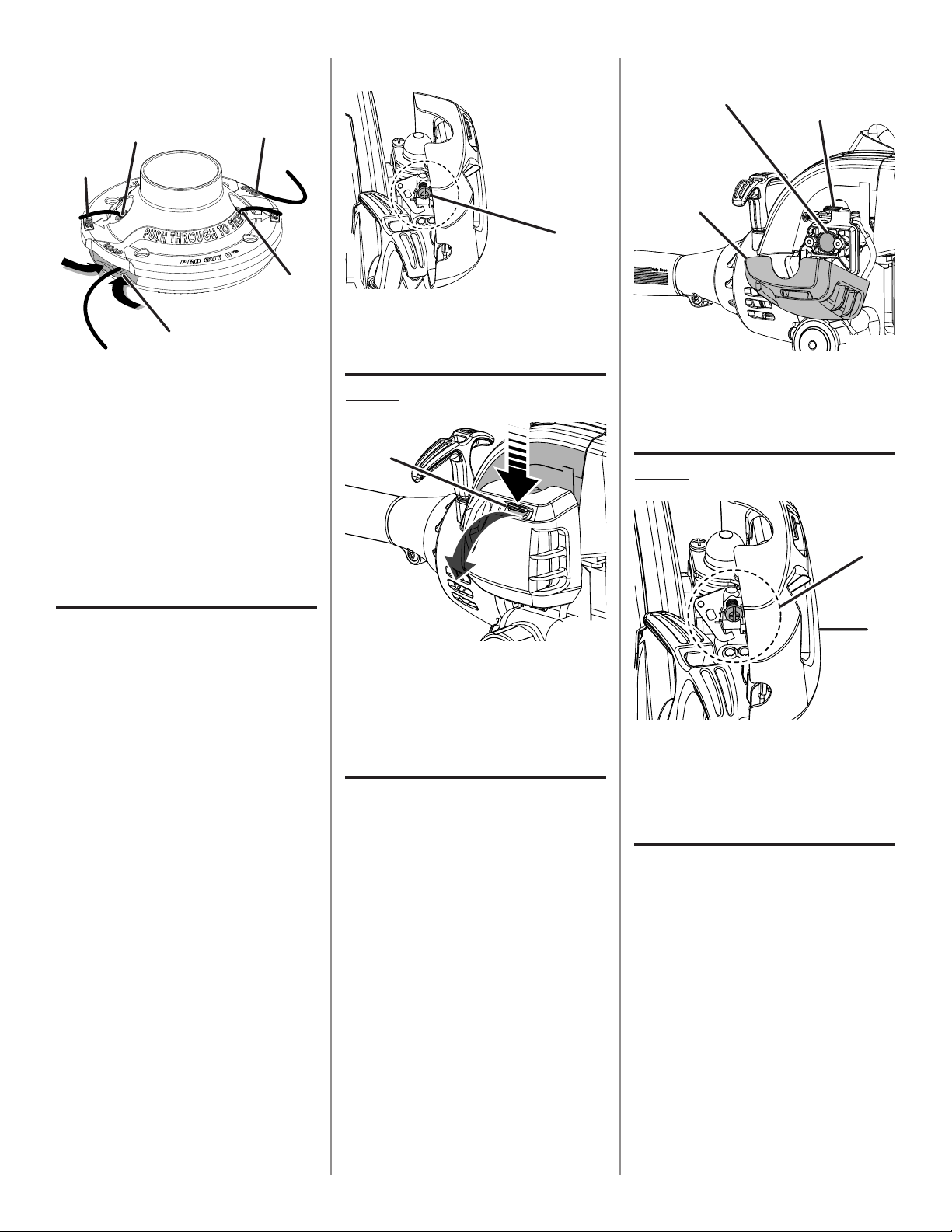
A - Idle speed screw (vis de ralenti, tornillo de
ajuste de la velocidad en vacío)
A
C
B
C
A
B
A
A - Latch (loquet, pestillo)
B - Pull cover to open (tirer sur le couvercle pour
l’ouvrir, tire de la tapa para abrirla)
C - Air filter cover (couvercle du filtre à air, tapa
del filtro de aire)
Fig. 23
A - Latch (loquet, pestillo)
B - Filter screen (filtre écran, filtro pantalla)
C - Air filter cover (couvercle du filtre à air, tapa
del filtro de aire)
A
B
Fig. 24
A - Idle speed screw (vis de ralenti, tornillo de
ajuste de la velocidad en vacío)
B - Air filter cover (couvercle du filtre à air, tapa
del filtro de aire)
A - Insert strings through slots until
approx. 1 in. protrudes from holes (insérer
les fils dans les fentes de manière à les
faire dépasser d’environ 25,4 mm [1 po],
introduzca los hilos a través de las ranuras
hasta que sobresalgan aproximadamente
25,4 mm [1 pulg.] de los orificios)
B - Hole (trou, agujero)
C - Pull strings from holes to remove (tirer les
fils hors des trous afin de les retirer, tire de
los hilos para retirarlos a través de
los orificios)
D - Slot (fente, ranura)

2
Introduction ......................................................................................................................................................................2
Introduction / Introducción
General Safety Rules .....................................................................................................................................................3-4
Règles de sécurité générales / Reglas de seguridad generales
Specific Safety Rules ........................................................................................................................................................ 4
Règles de sécurité particulières / Reglas de seguridad específicas
Symbols .........................................................................................................................................................................5-6
Symboles / Símbolos
Features ............................................................................................................................................................................ 6
Caractéristiques / Características
Assembly .......................................................................................................................................................................7-8
Assemblage / Armado
Operation .....................................................................................................................................................................8-11
Utilisation / Funcionamiento
Maintenance ..............................................................................................................................................................12-13
Entretien / Mantenimiento
Troubleshooting .............................................................................................................................................................. 14
Dépannage / Solución de problemas
Warranty ....................................................................................................................................................................15-17
Garantie / Garantía
Parts Ordering and Service ...............................................................................................................................Back Page
Commande de pièces et réparation / Pedidos de piezas y servicio ......................................................... Page arrière / Pág. posterior
TABLE OF CONTENTS
TABLE DES MATIÈRES / ÍNDICE DE CONTENIDO
INTRODUCTION
INTRODUCTION / INTRODUCCIÓN
This product has many features for making its use more pleasant and enjoyable. Safety, performance, and dependability
have been given top priority in the design of this product making it easy to maintain and operate.
* * *
Ce produit offre de nombreuses fonctions destinées à rendre son utilisation plus plaisante et satisfaisante. Lors de la
conception de ce produit, l’accent a été mis sur la sécurité, les performances et la fiabilité, afin d’en faire un outil facile à
utiliser et à entretenir.
* * *
Este producto ofrece numerosas características para hacer más agradable y placentero su uso. En el diseño de este producto
se ha conferido prioridad a la seguridad, el desempeño y la fiabilidad, por lo cual se facilita su manejo y mantenimiento.

3 — English
GENERAL SAFETY RULES
WARNING:
Read and understand all instructions. Failure to follow all
instructions listed below may result in electric shock, fire
and/or serious personal injury.
READ ALL INSTRUCTIONS
For safe operation, read and understand all instructions
before using this product. Follow all safety instructions.
Failure to follow all safety instructions listed below, can
result in serious personal injury.
Do not allow children or untrained individuals to use this
unit.
Never start or run the engine in a closed or poorly venti-
lated area; breathing exhaust fumes can kill.
Clear the work area before each use. Remove all objects
such as rocks, broken glass, nails, wire, or string which
can be thrown or become entangled in the cutting line
or blade.
Wear safety glasses or goggles that are marked to comply
with ANSI Z87.1 standard when operating this product.
A battery operated tool with integral batteries or a
separate battery pack must be recharged only with the
specified charger for the battery. A charger that may be
suitable for one type of battery may create a risk of fire
when used with another battery.
Use battery operated tool only with specifically designated
battery pack. Use of any other batteries may create a risk
of fire.
Use battery only with charger listed.
MODEL BATTERY PACK CHARGER
RY29550 130269012 140295003
Wear heavy, long pants, boots, and gloves. Do not wear
loose fitting clothing, short pants, sandals, or go barefoot.
Do not wear jewelry of any kind.
Heavy protective clothing may increase operator fatigue,
which could lead to heat stroke. During weather that is
hot and humid, heavy work should be scheduled for early
morning or late afternoon hours when temperatures are
cooler.
Product users on United States Forest Service land, and in
some states, must comply with fire prevention regulations.
This product is equipped with a spark arrestor; however,
other user requirements may apply. Check with your
federal, state, or local authorities.
Never operate this unit on the operator’s left side.
Secure long hair above shoulder level to prevent
entanglement in moving parts.
Keep all bystanders, children, and pets at least
50 ft. away. Bystanders should be encouraged to wear
eye protection. If you are approached, stop the engine
and cutting attachment. In the case of bladed units, there
is the added risk of injury to bystanders from being struck
with the moving blade in the event of a blade thrust or
other unexpected reaction of the saw.
Do not operate this unit when you are tired, ill, or under
the influence of alcohol, drugs, or medication.
Do not operate in poor lighting.
Keep firm footing and balance. Do not overreach.
Overreaching can result in loss of balance or exposure
to hot surfaces.
Keep all parts of your body away from any moving part.
To avoid hot surfaces, never operate the unit with the
bottom of the engine above waist level.
Do not touch area around the muffler or cylinder of the
unit, these parts get hot from operation.
Always stop the engine and remove the spark plug wire
before making any adjustments or repairs except for
carburetor adjustments.
Inspect the unit before each use for loose fasteners, fuel
leaks, etc. Replace any damaged parts before use.
The cutting attachment should never rotate at idle during
normal use. The cutting attachment may rotate at idle
during carburetor adjustments.
It has been reported that vibrations from hand-held tools
may contribute to a condition called Raynaud’s Syndrome
in certain individuals. Symptoms may include tingling,
numbness, and blanching of the fingers, usually apparent
upon exposure to cold. Hereditary factors, exposure to
cold and dampness, diet, smoking, and work practices
are all thought to contribute to the development of these
symptoms. It is presently unknown what, if any, vibrations
or extent of exposure may contribute to the condition.
There are measures that can be taken by the operator to
possibly reduce the effects of vibration:
a) Keep your body warm in cold weather. When oper-
ating the unit wear gloves to keep hands and wrists
warm. It is reported that cold weather is a major factor
contributing to Raynaud’s Syndrome.
b) After each period of operation, exercise to increase
blood circulation.
c) Take frequent work breaks. Limit the amount of
exposure per day.
d) Keep the tool well maintained, fasteners tightened,
and worn parts replaced.
If you experience any of the symptoms of this condition,
immediately discontinue use and see your physician about
these symptoms.
Mix and store fuel in a container approved for gasoline.
Mix fuel outdoors where there are no sparks or flames.
Wipe up any fuel spillage. Move 30 ft. away from refueling
site before starting engine. Slowly remove the fuel cap
after stopping engine. Do not smoke when refueling.

4 — English
SPECIFIC SAFETY RULES
Inspect before use. Replace damaged parts. Make sure
fasteners are in place and secure. Check for fuel leaks.
Replace string head if cracked, chipped, or damaged
in any way. Be sure the string head is properly installed
and securely fastened. Failure to do so can cause serious
injury.
Make sure all guards, straps, deflectors, and handles are
properly and securely attached.
Use only the manufacturer’s replacement string in the
cutting head. Do not use any other cutting attachment.
To install any other brand of replacement string or cutting
head to this string trimmer can result in serious personal
injury. Never use, for example, wire or wire-rope, which
can break off and become a dangerous projectile.
Never operate unit without the grass deflector in place
and in good condition.
Maintain a firm grip on both handles while trimming. Keep
string head below waist level. Never cut with the string
head located over 30 in. or more above the ground.
Do not place battery tools or their batteries near fire or
heat. This will reduce the risk of explosion and possibly
injury.
Always shut off engine before fueling. Never add fuel to
a machine with a running or hot engine. Move at least 30
ft. from refueling site before starting engine. Wipe up any
fuel spillage. Do not smoke! Failure to heed this warning
could result in serious personal injury.
Do not crush, drop or damage battery pack. Do not
use a battery pack or charger that has been dropped or
received a sharp blow. A damaged battery is subject to
explosion. Properly dispose of a dropped or damaged
battery immediately.
Batteries can explode in the presence of a source
of ignition, such as a pilot light. To reduce the risk of
serious personal injury, never use any cordless product
in the presence of open flame. An exploded battery can
propel debris and chemicals. If exposed, flush with water
immediately.
Do not charge battery tool in a damp or wet location.
Following this rule will reduce the risk of electric shock.
For best results, your battery tool should be charged
in a location where the temperature is more than
50°F but less than 100°F. To reduce the risk of serious
personal injury, do not store outside or in vehicles.
Under extreme usage or temperature conditions, battery
leakage may occur. If liquid comes in contact with your skin,
wash immediately with soap and water, then neutralize
with lemon juice or vinegar. If liquid gets into your eyes,
flush them with clean water for at least 10 minutes, then
seek immediate medical attention. Following this rule will
reduce the risk of serious personal injury.
Stop the engine and allow to cool before refueling or
storing the unit.
Allow the engine to cool; empty the fuel tank and secure
the unit from moving before transporting in a vehicle.
GENERAL SAFETY RULES
Wear your protective equipment and observe all safety
instructions. For units equipped with a clutch, be sure
the cutting attachment stops turning when the engine
idles. When the unit is turned off make sure the cutting
attachment has stopped before the unit is set down.

5 — English
SYMBOLS
Some of the following symbols may be used on this product. Please study them and learn their meaning. Proper inter-
pretation of these symbols will allow you to operate the product better and safer.
SYMBOL NAME DESIGNATION/EXPLANATION
Safety Alert Indicates a potential personal injury hazard.
V Volts Voltage
A Amperes Current
Hz Hertz Frequency (cycles per second)
W Watt Power
min Minutes Time
Alternating Current Type of current
Direct Current Type or a characteristic of current
n
o
No Load Speed Rotational speed, at no load
Class II Tool Double-insulated construction
.../min Per Minute Revolutions, strokes, surface speed, orbits etc., per minute
Wet Conditions Alert Do not expose to rain or use in damp locations.
Read the Operator’s Manual
To reduce the risk of injury, user must read and understand
operator’s manual before using this product.
Wear Eye and Hearing Protec-
tion
Wear eye protection which is marked to comply with ANSI Z87.1 as
well as hearing protection when operating this equipment.
Keep Bystanders Away Keep all bystanders at least 50 ft. away.
Ricochet
Thrown objects can ricochet and result in personal injury or prop-
erty damage.
No Blade
Do not install or use any type of blade on a product displaying this
symbol.
Gasoline and Lubricant
Use unleaded gasoline intended for motor vehicle use with an
octane rating of 87 [(R + M) / 2] or higher. This product is powered
by a 2-cycle engine and requires pre-mixing gasoline and 2-cycle
lubricant.

6 — English
SYMBOLS
The following signal words and meanings are intended to explain the levels of risk associated with this product.
SYMBOL SIGNAL MEANING
DANGER:
Indicates an imminently hazardous situation, which, if not avoided, will result
in death or serious injury.
WARNING:
Indicates a potentially hazardous situation, which, if not avoided, could result
in death or serious injury.
CAUTION:
Indicates a potentially hazardous situation, which, if not avoided, may result in
minor or moderate injury.
CAUTION:
(Without Safety Alert Symbol) Indicates a situation that may result in property
damage.
FEATURES
PRODUCT SPECIFICATIONS
Engine Displacement...................................................30 cc
Cutting Path Diameter .................................................18 in.
String Diameter ......................................................0.095 in.
Battery Voltage ......................................................... 12 Volt
Weight ....................................................................15.2 lbs.
KNOW YOUR STRING TRIMMER
See Figure 1.
The safe use of this product requires an understanding of
the information on the tool and in this operator’s manual as
well as a knowledge of the project you are attempting. Before
use of this product, familiarize yourself with all operating
features and safety rules.
CHARGER
The charger has a key-hole hanging feature for convenient,
space-saving storage. Screws should be installed so that
the center distance is 4-1/8 in.
ELECTRIC START
The string trimmer has an electric start which can be used
in place of the pull start.
PRO CUT II
TM
STRING HEAD
The string trimmer is provided with an additional string
head.
GRASS DEFLECTOR
The string trimmer includes a grass deflector that helps
protect you from flying debris.
SHOULDER STRAP
The string trimmer includes a shoulder strap that helps
support the product.
TOP-MOUNTED MOTOR
The top-mounted motor improves balance and is located
away from the dust and debris of the cutting area.

7 — English
ASSEMBLY
UNPACKING
This product requires assembly.
Carefully remove the tool and any accessories from the
box. Make sure that all items listed in the packing list are
included.
WARNING:
This new product has been shipped in a partially as-
sembled condition as described below. Carefully check
the packing list below to ensure all items are included in
the package; the packing list describes all loose items
that are not assembled to the product as shipped. Do not
operate the product if any packing list items are already
assembled to your product when you unpack it. Call the
customer service number below for assistance. Opera-
tion of a product that may have been improperly preas-
sembled could result in serious personal injury.
Inspect the tool carefully to make sure no breakage or
damage occurred during shipping.
Do not discard the packing material until you have care-
fully inspected and satisfactorily operated the tool.
If any parts are damaged or missing, please call
1-800-860-4050 for assistance.
PACKING LIST
Trimmer Assembly
Pro Cut II
TM
String Head
Spool Retainer
Shoulder Strap
12 Volt Battery
Charger
Front Handle
Wing Screw
Wing Nut
Bolt
Washer
Grass Deflector
Bottle of 2-Cycle Lubricant
Hanger Cap
Operator’s Manual
WARNING:
If any parts are damaged or missing do not operate this
product until the parts are replaced. Failure to heed this
warning could result in serious personal injury.
WARNING:
Do not attempt to modify this product or create acces-
sories not recommended for use with this product. Use of
this product with damaged or missing parts could result
in serious personal injury.
WARNING:
To prevent accidental starting that could cause serious
personal injury, always disconnect the engine spark plug
wire from the spark plug and remove battery pack when
assembling parts.
INSTALLING THE POWER HEAD SHAFT TO THE
ATTACHMENT
See Figure 2.
WARNING:
Never install, remove, or adjust any attachment while
power head is running. Failure to stop the engine can
cause serious personal injury.
The attachment connects to the power head shaft by means
of a coupler device.
Loosen the knob on the coupler of the power head shaft
and remove the end cap from the attachment.
Push in the button located on the attachment shaft. Align
the button with the guide recess on the power head coupler
and slide the two shafts together. Rotate the attachment
shaft until the button locks into the positioning hole.
NOTE: If the button does not release completely in the
positioning hole, the shafts are not locked into place.
Slightly rotate from side to side until the button is locked
into place.
Tighten the knob securely.
WARNING:
Be certain the knob is fully tightened before operating
equipment; check it periodically for tightness during use
to avoid serious personal injury.
REMOVING THE ATTACHMENT FROM THE
POWER HEAD
For removing or changing the attachment:
Loosen the knob.
Push in the button and twist the shafts to remove and
separate ends.

8 — English
ASSEMBLY
WARNING:
Do not allow familiarity with this product to make you
careless. Remember that a careless fraction of a second is
sufficient to inflict serious injury.
WARNING:
Always wear eye protection marked to comply with
ANSI Z87.1. Failure to do so could result in objects be-
ing thrown into your eyes, resulting in possible serious
injury.
WARNING:
Do not use any attachments or accessories not recom-
mended by the manufacturer of this product. The use of
attachments or accessories not recommended can result
in serious personal injury.
OPERATION
ATTACHING THE HANGER CAP
See Figure 3.
There are two ways to hang your attachment for storage.
To use the hanger cap, push in the button and place the
hanger cap over end of the lower end attachment shaft.
Slightly rotate the cap from side to side until the button
locks into place.
The secondary hole in the attachment shaft can be used
for hanging purposes as well.
ATTACHING THE FRONT HANDLE
See Figure 4.
Remove wing nut, washer, and bolt from the front
handle.
Install the front handle onto the top side of the drive shaft
housing.
NOTE: The open side of the handle should face the
operator.
Place the bolt through the front handle.
NOTE: The hex bolt head fits inside the hex recess molded
into one side of the handle.
Reinstall the washer and wing nut.
Tighten wing nut securely.
WARNING:
The line cutting blade on the grass deflector is sharp.
Avoid contact with the blade. Failure to avoid contact
can result in serious personal injury.
ATTACHING THE GRASS DEFLECTOR
See Figure 5.
Remove the wing screw from the grass deflector.
Insert the tab on the mounting bracket in the slot on the
grass deflector.
Align the screw hole in the mounting bracket with the
screw hole in the grass deflector.
Insert the wing screw through the mounting bracket and
into the grass deflector.
Tighten the screw securely.
ATTACHING THE SHOULDER STRAP
See Figure 6.
Follow these steps to attach the shoulder strap.
Connect the latch on the strap to the hanger bracket.
Adjust the strap to a comfortable position.
FUELING AND REFUELING THE TRIMMER
FUEL MIXTURE
This product is powered by a 2-cycle engine and requires
pre-mixing gasoline and 2-cycle lubricant. Pre-mix unleaded
gasoline and 2-cycle engine lubricant in a clean 1 gallon
container approved for gasoline.
Recommended fuel: This engine is certified to operate on
unleaded gasoline intended for automotive use.
Mix a high quality 2-cycle engine lubricant at 2.6 oz. per
gallon (US).
Do not use automotive lubricant or 2-cycle outboard
lubricant.
DO NOT mix quantities larger than usable in a 30 day
period.
HIGH QUALITY 2-CYCLE ENGINE LUBRICANT
GASOLINE LUBRICANT
1 gallon (US) 2.6 oz.
1 liter 20 cc (20 ml)

9 — English
FILLING TANK
C lean surf ace around fuel cap to pre vent
contamination.
Loosen fuel cap slowly. Rest the cap on a clean
surface.
Carefully pour fuel into the tank. Avoid spillage.
Prior to replacing the fuel cap, clean and inspect the
gasket.
Immediately replace fuel cap and hand tighten. Wipe up
any fuel spillage.
NOTE: It is normal for smoke to be emitted from a new
engine after first use.
WARNING:
Always shut off engine before fueling. Never add fuel to
a machine with a running or hot engine. Move at least
30 ft. from refueling site before starting engine. Do not
smoke! Failure to heed this warning could result in seri-
ous personal injury.
OXYGENATED FUELS
Some conventional gasolines are blended with alcohol or an
ether compound. These gasolines are collectively referred
to as oxygenated fuels. To meet clean air standards, some
areas of the United States and Canada use oxygenated fuels
to help reduce emissions.
If using an oxygenated fuel, make sure it is unleaded and
meets the minimum octane rating requirements. Before using
an oxygenated fuel, try to confirm the fuel’s contents. Some
states/provinces require this information to be posted on the
pump. The following are the EPA approved percentages of
oxygenates:
Ethanol (ethyl or grain alcohol) 10% by volume. You
may use gasoline containing up to 10% ethanol by volume.
Gasoline containing ethanol may be marketed under the
name “Gasohol.” Do not use E85 fuel.
MTBE (methyl tertiary butyl ether) 15% by volume. You
may use gasoline containing up to 15% MTBE by volume.
Methanol (methyl or wood alcohol) 5% by volume. You
may use gasoline containing up to 5% methanol by volume
as long as it also contains cosolvents and corrosion inhibitors
to protect the fuel system. Gasoline containing more than 5%
methanol by volume may cause starting and/or performance
problems. It may also damage metal, rubber, and plastic
parts of the product or your fuel system.
If you notice any undesirable operating symptoms, try another
service station or switch to another brand of gasoline.
NOTE: Fuel system damage or performance problems
resulting from the use of an oxygenated fuel containing more
than the percentages of oxygenates stated previously are
not covered under warranty.
OPERATION
CAUTION:
If at any point during the charging process none of the
LEDs are lit, remove the battery pack from the charger
to avoid damaging the product. DO NOT insert another
battery. Return the charger and battery to your nearest
service center for service or replacement.
CHARGING THE BATTERY PACK
The battery pack for this tool has been shipped in a low
charge condition to prevent possible problems. Therefore,
you should charge overnight prior to use.
NOTE: Batteries will not reach full charge the first time they
are charged. Allow several cycles (operation followed by
recharging) for them to become fully charged.
Charge battery pack only with the charging assembly
provided.
Make sure power supply is normal household voltage,
120 V, AC only, 60 Hz.
Connect charger to power supply.
Place battery pack in charging stand. Align raised rib
on battery pack with groove in charging stand. See
Figure 7.
Press down on battery pack to be sure contacts on battery
pack engage properly with contacts in charging stand.
The charge indicator light (LED), located on the charging
stand, will light up red and glow when the charger
is properly connected to power supply. This light
indicates the charger is operating properly. It will remain
on until battery pack is removed from charging stand or
charger is disconnected from power supply.
After normal usage, 3 hours or less of charging time is
required to fully recharge battery pack.
If both red and orange LED indicators glow, the
battery pack is deeply or completely discharged, and
6 hours or longer of charging time is required to fully
recharge battery pack.
NOTE: If charger does not charge battery pack or orange
LED continues to glow after more than 30 minutes of
charging, return battery pack and charging assembly to
your nearest Ryobi Authorized Service Center for electrical
check.
The battery pack will become slightly warm to the touch
while charging. This is normal and does not indicate a
problem.
Do not place charger in an area of extreme heat or cold.
It will work best at normal room temperature.
When batteries become fully charged, unplug charger
from power supply and remove the battery pack.

10 — English
OPERATION
CHARGING A HOT BATTERY PACK
When using the tool continuously, the batteries in the
battery pack will become hot. You should let a hot battery
pack cool down for approximately 30 minutes before
attempting to recharge.
NOTE: This situation only occurs when continuous use
of the string trimmer causes the batteries to become hot.
It does not occur under normal circumstances. Refer to
CHARGING THE BATTERY PACK for normal recharging
of batteries. If the charging assembly does not charge the
battery pack under normal circumstances, return both the
battery pack and charging assembly to your nearest Ryobi
Authorized Service Center for electrical check.
TO INSTALL BATTERY PACK
See Figure 8.
Place the battery pack in the string trimmer. Align raised
rib on battery pack with groove in string trimmer’s battery
port.
Make sure the latches on each side of the battery pack
snap in place and that battery pack is secured in string
trimmer before beginning operation.
TO REMOVE BATTERY PACK
Locate latches on side of battery pack and depress both
sides to release battery pack from the string trimmer.
Remove battery pack from the string trimmer.
OPERATING THE TRIMMER
See Figure 9.
WARNING:
Always position the unit on the operator’s right side. The
use of the unit on the operator’s left side will expose
the user to hot surfaces and can result in possible burn
injury.
WARNING:
To avoid burns from hot surfaces, never operate unit with
the bottom of the engine above waist level.
Hold the trimmer with your right hand on the rear handle
and your left hand on the front handle. Keep a firm grip with
both hands while in operation. Trimmer should be held at a
comfortable position with the rear handle about hip height.
Always operate trimmer at full throttle. Cut tall grass from
the top down. This will prevent grass from wrapping around
the shaft housing and string head which could cause
damage from overheating. If grass becomes wrapped around
the string head, STOP THE ENGINE, disconnect the spark
plug wire, and remove the grass. Prolonged cutting at partial
throttle will result in lubricant dripping from the muffler.
WARNING:
Always hold the string trimmer away from the body keep-
ing clearance between the body and the product. Any
contact with the housing or string trimmer cutting head can
result in burns and/or other serious personal injury.
TO ADVANCE THE CUTTING LINE
String advance is controlled by tapping the string head on
grass while running engine at full throttle.
Run engine at full throttle.
Tap the knob on ground to advance string. The string
advances each time the knob is tapped. Do not hold the
knob on the ground.
NOTE: The line trimming cut-off blade on the grass deflector
will cut the line to the correct length.
NOTE: If the string is worn too short you may not be able to
advance the string by tapping it on the ground. If so, stop
the engine, and manually advance the string.
To advance the cutting line manually:
Stop the engine and disconnect the spark plug wire.
Push the knob in while pulling on string(s) to manually
advance the string.
CUTTING TIPS
See Figures 9 - 10.
Avoid hot surfaces by always keeping the tool away from
your body. (Proper operating position shown in figure 9.)
Keep the trimmer tilted toward the area being cut; this is
the best cutting area.
The trimmer cuts when passing the unit from left to right.
This will avoid throwing debris at the operator. Avoid
cutting in the dangerous area shown in illustration.
Use the tip of string to do the cutting; do not force string
head into uncut grass.
Wire and picket fences cause extra string wear, even
breakage. Stone and brick walls, curbs, and wood may
wear string rapidly.
Avoid trees and shrubs. Tree bark, wood moldings, siding,
and fence posts can easily be damaged by the string.
GRASS DEFLECTOR STRING TRIMMING CUT-
OFF BLADE
See Figure 11.
The trimmer is equipped with a string trimming cut-off blade
on the grass deflector. For best cutting, advance string until
it is trimmed to length by the cut-off blade. Advance the
string whenever you hear the engine running faster than
normal, or when trimming efficiency diminishes. This will
maintain best performance and keep the string long enough
to advance properly.

11 — English
OPERATION
STARTING AND STOPPING
See Figures 12 - 14.
When starting the string trimmer for the first time or when
the battery voltage is low, it may be necessary to manually
start the string trimmer.
FOR MANUAL START:
To start a cold engine:
DO NOT squeeze the throttle trigger until the engine starts
and runs.
Lay the trimmer on a flat, bare surface.
PRIME - Press the primer bulb 7 times.
SET the start lever to the START position.
PULL the recoil starter until the engine starts.
Wait 6-10 seconds, then squeeze the trigger to run.
NOTE: Squeezing and releasing the throttle trigger releases
the start lever to the RUN position.
To start a warm engine:
PULL the recoil starter until the engine starts.
To stop the engine:
Press and hold the switch in the stop “ ” position until
the engine stops.
FOR ELECTRIC START:
To start a cold engine:
DO NOT squeeze the throttle trigger until the engine starts
and runs.
Lay the trimmer on a flat, bare surface.
PRIME - Press the primer bulb 7 times.
SET the start lever to the START position.
PRESS ignition switch.
RELEASE ignition switch after engine starts.
Wait 6-10 seconds, then squeeze the throttle trigger to run.
NOTE: Squeezing and releasing the throttle trigger releases
the start lever to the RUN position.
To start a warm engine:
PRESS ignition switch.
Lay the trimmer on a flat, bare surface.
RELEASE ignition switch after engine starts.

12 — English
MAINTENANCE
NOTE: Only use the knob to tighten the bolt. The use of
other tools may allow overtightening of the bolt, which
could damage the string head.
NOTE: For the BC30, the gear head locking tool can be
inserted through the slot in the flanged washer and gear
head to help hold the string head still.
If removed, replace the spring into the string head and
push down to seat.
Reinstall the spool. The spool should be placed so “This
side out for straight shaft” is visible.
Replace the knob in the spool.
Replace the string head cover, aligning latches with
openings in the string head. Press cover and string head
together until both latches snap into openings securely.
Install string as described in the next section of this
manual.
INSTALLING STRING IN REEL EASY STRING
HEAD
See Figures 17 - 18.
Use .095 in. diameter monofilament string.
Stop the engine and disconnect the spark plug wire.
Cut one piece of string approximately 25 ft. in length.
Rotate knob on string head until line on knob aligns with
arrows on top of string head.
Insert one end of string into eyelet located on the side of
the string head and push until string comes out through
eyelet on the other side. Continue to push string through
the string head until the middle section of the string is
inside the string head and string outside the string head
is evenly divided on each side.
Rotate the knob on the string head to wind the string. If
using the CS30, knob should be rotated counterclock-
wise. If using the SS30 or the BC30, knob should be
rotated clockwise. Wind the string until approximately
8 in. remains protruding from the string head.
INSTALLING PRO CUT II STRING HEAD
TM
See Figure 19.
Stop the engine and disconnect the spark plug wire.
Remove currently installed string head.
Install the string head on the drive shaft until fully
seated.
Install the spool retainer and turn counterclockwise.
Install string as described in the next section of this
manual.
WARNING:
When servicing, use only identical replacement parts.
Use of any other parts may create a hazard or cause
product damage.
WARNING:
Always wear eye protection marked to comply with
ANSI Z87.1. Failure to do so could result in objects be-
ing thrown into your eyes, resulting in possible serious
injury.
WARNING:
Before inspecting, cleaning, or servicing the machine,
shut off engine, wait for all moving parts to stop, and
disconnect spark plug wire and move it away from spark
plug. Failure to follow these instructions can result in
serious personal injury or property damage.
GENERAL MAINTENANCE
Avoid using solvents when cleaning plastic parts. Most
plastics are susceptible to damage from various types of
commercial solvents and may be damaged by their use. Use
clean cloths to remove dirt, dust, lubricant, grease, etc.
WARNING:
Do not at any time let brake fluids, gasoline, petroleum-
based products, penetrating lubricants, etc., come in
contact with plastic parts. Chemicals can damage,
weaken or destroy plastic which may result in serious
personal injury.
You can often make adjustments and repairs described
here.
For other repairs, have the trimmer serviced by an
authorized service dealer.
INSTALLING REEL EASY STRING HEAD
See Figures 15 - 16.
Stop the engine and disconnect the spark plug wire.
Remove currently installed string head.
Open the Reel Easy String Head by depressing the latches
on each side. The contents of the string head are spring
loaded, so keep your other hand over the string head
cover while depressing the latches.
Remove the string head cover, knob, and spool and set
aside.
Place the string head on the drive shaft. Make sure the
string head is fully seated.
Install the hex bolt into the opening on the drive shaft
and secure using the hex-shaped opening in the knob
to tighten.
 Loading...