


RY15520
OPERATOR’S MANUAL
MANUEL D’UTILISATION
MANUAL DEL OPERADOR
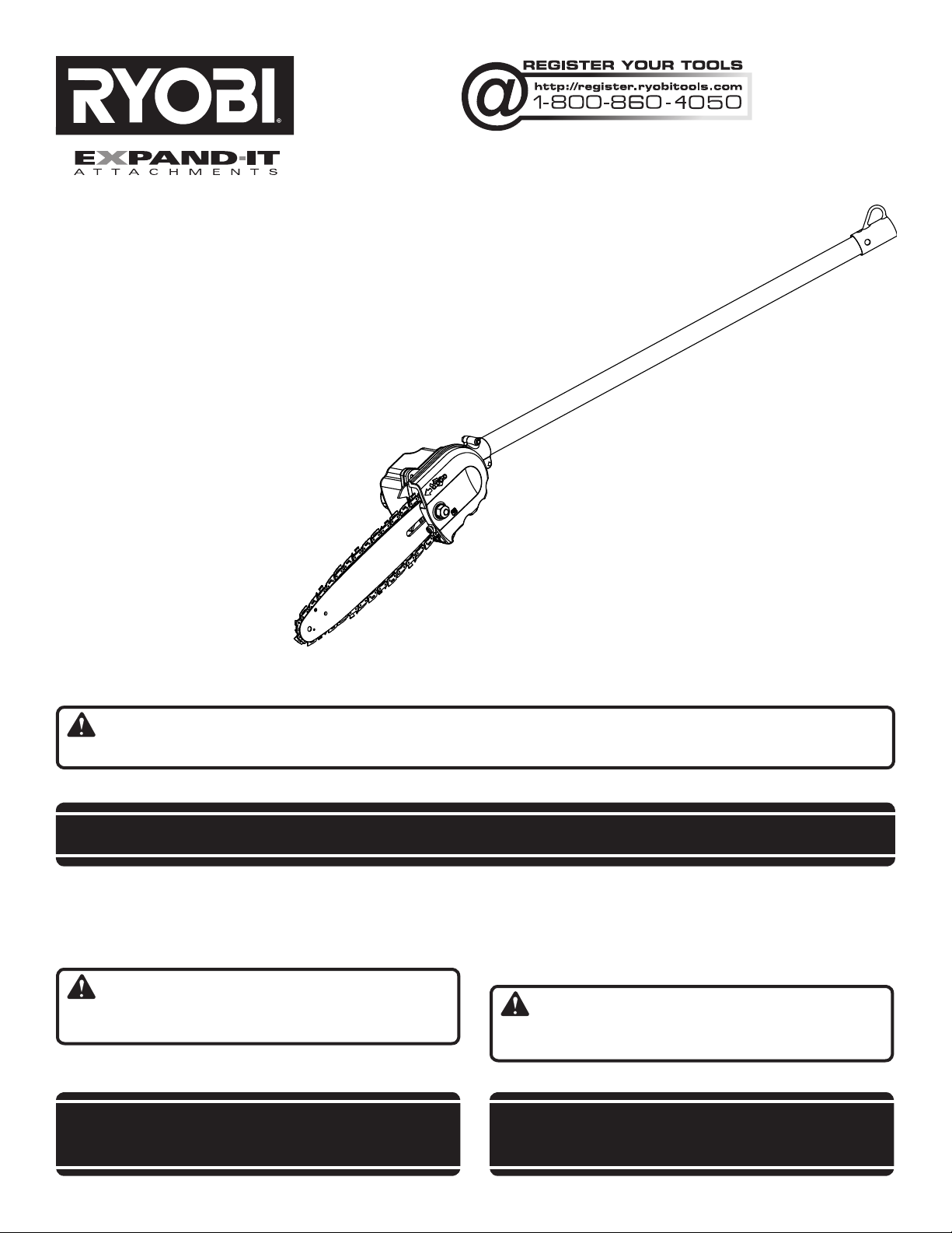
PRUNER ATTACHMENT
ACCESSOIRE D’ÉLAGAGE
ACCESORIO PARA PODAR
RY15520
Your pruner attachment has been engineered and manufactured to our high standard for dependability, ease of operation,
and operator safety. When properly cared for, it will give you years of rugged, trouble-free performance.
WARNING: To reduce the risk of injury, the user must read and understand the operator’s manual before using
this product.
Thank you for your purchase.
SAVE THIS MANUAL FOR FUTURE REFERENCE
Votre accessoire d’élagage a été conçu et fabriqué conformément
aux strictes normes de fiabilité, simplicité d’emploi et sécurité
d’utilisation. Correctement entretenu, il vous donnera des années
de fonctionnement robuste et sans problème.
AVERTISSEMENT : Pour réduire les risques de
blessures, l’utilisateur doit lire et veiller à bien comprendre le
manuel d’utilisation avant d’employer ce produit.
Merci de votre achat.
Su nuevo accesorio para podar ha sido diseñado y fabricado
de conformidad con estrictas normas de calidad para brindar
fiabilidad, facilidad de uso y seguridad para el operador. Con el
debido cuidado, le brindará muchos años de sólido y eficiente
funcionamiento.
ADVERTENCIA: Para reducir el riesgo de lesiones,
el usuario debe leer y comprender el manual del operador antes
de usar este producto.
Le agradecemos su compra.
CONSERVER CE MANUEL POUR
FUTURE RÉFÉRENCE
GUARDE ESTE MANUAL PARA
FUTURAS CONSULTAS

See this fold-out section for all of the figures
referenced in the operator’s manual.
Consulter l’encart à volets afin d’examiner
toutes les figures mentionnées dans le manuel
d’utilisation.
Consulte esta sección desplegable para ver todas
las figuras a las que se hace referencia en el
manual del operador.
ii
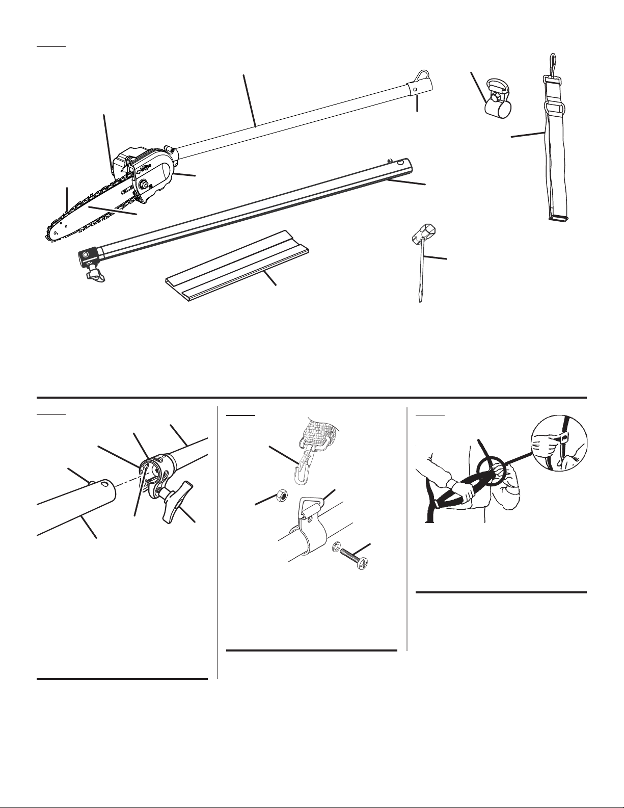
Fig. 1
B
C
E
D
A - Pruner attachment shaft (arbre d’accessoire
d’élagage, eje del accesorio para podar)
B - Chain oiler tank cap (capuchon du réservoir
d’huile de chaîne, tapa del tanque lubricador
de la cadena)
C - Chain (chaîne, cadena)
D- Bar (guide, barra)
A
F
E - Gear case (carter d’engrenages, caja de
engranajes)
F - Scabbard (fourreau, funda)
G - Combination wrench (clé mixte, llave de
combinación)
H
- Extension shaft (arbre de rallonge, eje de
extensión)
K
J
I
H
G
I
- Shoulder strap (bandoulière, correa para
el hombro)
J
- Hanger cap (capuchon de suspension, tapa
de suspensión)
K - Strap hanger (dispositif d’accrochage,
colgador de la correa)
Fig. 2
B
A
C
D
F
G
E
A - Power head shaft (arbre moteur, cabezal
motor eje)
B - Coupler (coupleur, acoplador)
C - Guide recess (renfoncement du guide, hueco
guía)
D - Button (bouton, botón)
E - Extension shaft (arbre de rallonge, eje de
extensíon)
F - Positioning hole (trou de positionnement,
orificio de posicionamiento)
G - Knob (bouton, perilla)
Fig. 3
A
D
B
C
A - Shoulder strap clip (boucle, clip de la correa
para el hombro)
B - Lock nut (écrou frein, tuerca)
C - Bolt (boulon, perno)
D - Strap hanger (dispositif d’accrochage,
colgador para la correa)
Fig. 4
A
A - Slide clip up or down to adjust shoulder
strap (faire glisser la boucle vers le haut ou
le bas pour ajuster la bandoulière, deslice el
clip hacia arriba o hacia abajo para ajustar la
correa para el hombro)
iii
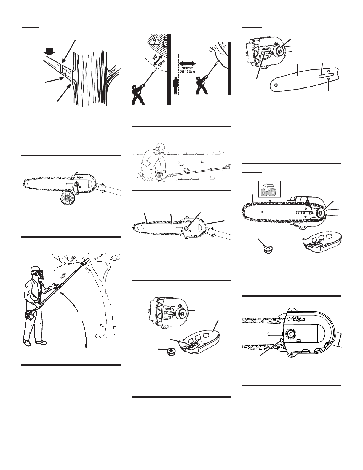
Fig. 5
Fig. 8
Fig. 12
A
B
C
D
A - Second cut (deuxième coupe, segundo
corte)
B - Load (charge, carga)
C - First cut 1/4 diameter (première coupe 1/4
du diamètre, primer corte 1/4 del diámetro)
D - Final cut (coupe finale, corte final)
Fig. 6
A
A - Cutting guide (guide de coupe, guía de
corte)
Fig. 7
A - Minimum 50’ 15m (minimum 50’ 15m,
minimo 50’ 15m)
Fig. 9
Fig. 10
A
A - Chain (chaîne, cadena)
B - Bar (guide, barra)
C - Bar nut (écrou du guide, tuerca de la barra)
D - Drivecase cover (carter d’engrenages, tapa
de la caja de la transmisión)
B
C
D
Fig. 11
A
C
D
B
E
A - Sprocket (pignon, rueda dentada)
B - Bar stud (goujon de guide, perno de la
barra)
C - Bar (guide, barra)
D - Bar stud slot (fente du goujon de guide,
ranura del perno en la barra)
E - Chain tensioning pin hole (trou d’axe de
tension de chaîne, orificio del pasador tensor
de la cadena)
Fig. 13
B
C
A - Chain rotation (rotation de la chaîne, rotación
de la cadena)
B - Chain (chaîne, cadena)
C - Bar nut (écrou du guide, tuerca de la barra)
D - Sprocket (pignon, rueda dentada)
A
D
A
A - 60° maximum (60° maximum, 60° máximo)
C
A
B
A - Chain tensioning pin (axe de tension de
chaîne, pasador tensor de la cadena)
B - Bar nut (écrou du guide, tuerca de la barra)
C - Drivecase cover (carter d’engrenages, tapa
de la caja de la transmisión)
iv
Fig. 14
A
A - Chain tensioning screw (vis de tension de
chaîne, tornillo tensor de la cadena)
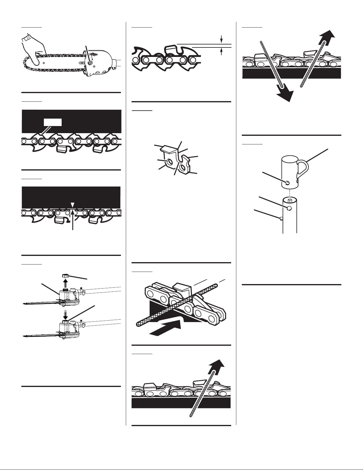
Fig. 15
Fig. 19
Fig. 23
A
A
A
A - Bar nut (écrou du guide, tuerca de la barra)
Fig. 16
A
A - Flats (méplats, partes planas)
Fig. 17
APPROX .050 in. /
ENVIRON 1,25 MM (0,050 PO) /
APROX 1,25 MM (0,050 PULG.)
Fig. 18
B
A
A - Depth gauge setting, (réglage du limiteur
de profondeur, ajuste del calibrador de
profundidad)
Fig. 20
PARTS OF A CUTTER / PIÈCES D’UNE
DENT / PARTES DE UN DIENTE DE CORTE
A
B
C
D
A - Cutting corner (coupe du coin, esquina de
corte)
B - Top plate (plaquette supérieure, placa
superior)
C - Rivet hole (trou de rivet, orificio del
remache)
D - Heel (talonnage, talón)
E - Gullet (creux, garganta)
F - Toe (sabot, puntera)
G - Depth gauge (limiteur de profondeur, calibre
de profundidad)
H - Side plate (plaque latérale, placa lateral)
H
G
E
F
Fig. 21
B
A - Left hand cutters (dents de gauche, dientes
de corte izquierdos)
B - Right hand cutters (dents de droite, dientes
de corte derechos)
Fig. 24
A
B
C
D
A - Hanger cap (capuchon de suspension, tapa
de suspensión)
B - Hole (trou, orificio)
C - Secondary hole (trou secondaire, orificio
secundario)
D - Button (bouton, botón)
C
A - Remove cap (retirer le bouchon, quite la
tapa)
B - Chain oiler tank (réservoir d’huile de chaîne,
tanque del lubricador de la cadena)
C - Replace cap (remettre le bouchon en place,
vuelva a colocar la tapa)
Fig. 22
v

TABLE OF CONTENTS
TABLE DES MATIÈRES / ÍNDICE DE CONTENIDO
Introduction ......................................................................................................................................................................2
Introduction / Introducción
General Safety Rules ..................................................................................................................................................... 3-4
Règles de sécurité générales / Reglas de seguridad generales
Specific Safety Rules ........................................................................................................................................................ 4
Règles de sécurité particulières / Reglas de seguridad específicas
Symbols ............................................................................................................................................................................ 5
Symboles / Símbolos
Features ............................................................................................................................................................................6
Caractéristiques / Características
Assembly .......................................................................................................................................................................6-7
Assemblage / Armado
Operation .......................................................................................................................................................................7-8
Utilisation / Funcionamiento
Maintenance ................................................................................................................................................................9-11
Entretien / Mantenimiento
Troubleshooting .............................................................................................................................................................. 12
Dépannage / Corrección de problemas
Warranty .........................................................................................................................................................................13
Garantie / Garantía
Illustrated Parts List ................................................................................................................................................... 14-15
Liste des pièces illustrées / Lista de piezas ilustradas
Parts Ordering and Service ...............................................................................................................................Back Page
Commande de pièces et réparation / Pedidos de piezas y servicio ......................................................... Page arrière / Pág. posterior
INTRODUCTION
INTRODUCTION / INTRODUCCIÓN
This product has many features for making its use more pleasant and enjoyable. Safety, performance, and dependability
have been given top priority in the design of this product making it easy to maintain and operate.
* * *
Ce produit offre de nombreuses fonctions destinées à rendre son utilisation plus plaisante et satisfaisante. Lors de la
conception de ce produit, l’accent a été mis sur la sécurité, les performances et la fiabilité, afin d’en faire un outil facile à
utiliser et à entretenir.
* * *
Este producto ofrece numerosas características para hacer más agradable y placentero su uso. En el diseño de este producto
se ha conferido prioridad a la seguridad, el desempeño y la fiabilidad, por lo cual se facilita su manejo y mantenimiento.
2

GENERAL SAFETY RULES
WARNING:
Read and understand all instructions. Failure to fol-
low all instructions listed below, may result in electric
shock, fire, and/or serious personal injury.
SAVE THESE INSTRUCTIONS
Read these instructions and the instructions for the power
head thoroughly before using pruner.
Know the tool. Read and understand the operator’s
manual and observe the warnings and instruction labels
affixed to the tool.
Do not allow children or untrained individuals to use this
unit.
Always wear eye protection with side shields marked to
comply with ANSI Z87.1, along with hearing and head
protection when operating this unit.
Wear heavy long pants, boots, and gloves. Do not wear
loose fitting clothing, short pants, jewelry of any kind,
sandals, or go barefoot.
Secure long hair so it is above shoulder level to prevent
entanglement in any moving parts.
Keep all bystanders, children, and pets at least 50 ft.
away.
Stay alert, watch what you are doing, and use common
sense when operating a power tool. Do not use tool while
tired or under the influence of drugs, alcohol, or medication. A moment of inattention while operating power tools
may result in serious personal injury.
Do not operate in poor lighting.
Do not overreach. Keep proper footing and balance at all
times. Proper footing and balance enables better control
of the tool in unexpected situations.
Keep all parts of your body away from any moving part.
Inspect unit before each use for loose fasteners and
damaged or missing parts. Correct before using the
attachment. Failure to do so can cause serious injury.
Use only original manufacturer’s replacement parts.
Failure to do so may cause poor performance, possible
injury, and will void your warranty.
Do not, under any circumstance, use any attachment or
accessory on this product, which was not provided with
the product, or identified as appropriate for use with this
product in the operator’s manual.
Avoid dangerous environments. Do not use the attach-
ment in damp or wet locations. Do not use in rain.
Use the right attachment. Do not use attachment for any
job except that for which it is intended.
Keep hands away from cutting area. Keep hands away
from blades. Do not reach underneath work or around
or over the blade while blade is rotating. Do not attempt
to remove cut material when blade is moving.
Blade coasts after being turned off.
Do not touch areas around the muffler or cylinder of a gas
power head. These parts get hot from operation. Contact
with hot surfaces could result in possible serious personal
injury.
Always stop the engine or motor and remove the spark
plug wire or disconnect from the power supply before
making any adjustments or repairs except for carburetor
adjustments.
WHEN USING AN ELECTRIC POWER HEAD:
Do not leave appliance when plugged in. Unplug from
outlet when not in use and before servicing.
Do not allow to be used as a toy. Close attention is nec-
essary when used by or near children.
Use only as described in this manual. Use only manufac-
turer’s recommended attachments.
Do not use with damaged cord or plug. If appliance is
not working as it should, has been dropped, damaged,
left outdoors, or dropped into water, return it to a service
center.
Do not pull or carry by cord, use cord as a handle, close a
door on cord, or pull cord around sharp edges or corners.
Do not run appliance over cord. Keep cord away from
heated surfaces.
Do not unplug by pulling on cord. To unplug, grasp the
plug, not the cord.
Do not handle plug or appliance with wet hands.
Do not put any object into openings. Do not use with any
opening blocked; keep free of dust, lint, hair, and anything
that may reduce air flow.
Keep hair, loose clothing, fingers, and all parts of body
away from openings and moving parts.
Turn off all controls before unplugging.
This appliance is provided with double insulation. Use
only identical replacement parts. See Instructions for
Servicing of Double-Insulated Appliances.
3 — English

GENERAL SAFETY RULES
SERVICING OF DOUBLE-INSULATED APPLIANCES. A
double-insulated appliance is marked with one or more
of the following: The words “DOUBLE INSULATION” or
“DOUBLE INSULATED” or the double insulation symbol
(square within a square). In a double-insulated appliance, two systems of insulation are provided instead of
grounding. No grounding means is provided on a double-
SPECIFIC SAFETY RULES
insulated appliance, nor should a means for grounding
be added to the appliance. Servicing a double-insulated
appliance requires extreme care and knowledge of the
system, and should be done only by qualified service
personnel. Replacement parts for a double-insulated
appliance must be identical to the parts they replace.
Kickback is a dangerous reaction that can lead to serious
injury. Kickback may occur when the moving chain contacts an object at the upper portion of the tip of the guide
bar or when the wood closes in and pinches the chain
in the cut. Contact at the upper portion of the tip of the
guide bar can cause the chain to dig into the object and
stop the chain for an instant. The result is a lightning fast,
reverse reaction which kicks the guide bar up and back
toward the operator. If the chain is pinched along the top
of the guide bar, the guide bar can be driven rapidly back
toward the operator. Either of these reactions can cause
loss of tool control which can result in serious injury. Do
not rely exclusively upon the safety devices built into the
tool. As a pruner user, you should take several steps to
keep your cutting jobs free from accident or injury.
With a basic understanding of kickback, you can reduce
or eliminate the element of surprise. Sudden surprise
contributes to accidents.
Make sure that the area in which you are cutting is free
from obstructions. Do not let the nose of the guide bar
contact a log, branch, fence, or any other obstruction
while you are operating the unit.
Always cut with the engine or motor running at full speed.
Fully squeeze the trigger and maintain a steady cutting
speed.
Follow the sharpening and maintenance instructions for
the chain.
Use only the replacement guide bars and low kickback
chains specified for this unit.
Do not force tool. Use the correct tool for your applica-
tion. The correct tool will do the job better and safer at
the rate for which it is designed.
Do not use on a ladder or unstable support. Stable foot-
ing on a solid surface enables better control of the tool
in unexpected situations.
Never let anyone use the tool who has not received
adequate instructions in its proper use. This applies to
rentals as well as privately owned units and also to the
power head it is attached to.
To protect yourself from electrocution, do not operate
within 50 ft. of overhead electrical lines.
To protect yourself from falling branches, do not stand di-
rectly under the branch or limb being cut. This unit should
not be held at an angle over 60° from ground level.
Keep the handles dry, clean, and free of oil or fuel mix-
ture.
Before you start the engine or motor, make sure the chain
is not contacting any object.
Shut off the engine or motor and make sure the cutting
attachment has stopped before setting the unit down.
DANGER! Serious injury or death from electrocution if
power lines are contacted. Never use near any electrical
source, wires, or powerlines.
Wear face shield and hard hat to protect against falling
debris. Always have a clear work area and retreat path.
Be aware of limb/branch location to avoid falling limbs
and debris. Keep bystanders 50 feet away when operating saw.
Store Idle Appliance Indoors — When not in use, product
should be stored indoors in a dry and high or locked up
place—out of the reach of children.
Save these instructions. Refer to them frequently and
use them to instruct others who may use this tool.
If you loan someone this tool, loan them these instructions also to prevent misuse of the product and
possible injury.
NOTE: SEE YOUR POWER HEAD OPERATOR’S MANUAL FOR ADDITIONAL SPECIFIC SAFETY RULES.
SAVE THESE INSTRUCTIONS
4 — English

SYMBOLS
The following signal words and meanings are intended to explain the levels of risk associated with this product.
SYMBOL SIGNAL MEANING
DANGER:
WARNING:
CAUTION:
CAUTION:
Some of the following symbols may be used on this product. Please study them and learn their meaning. Proper
interpretation of these symbols will allow you to operate the product better and safer.
Indicates an imminently hazardous situation, which, if not avoided, will result
in death or serious injury.
Indicates a potentially hazardous situation, which, if not avoided, could result
in death or serious injury.
Indicates a potentially hazardous situation, which, if not avoided, may result in
minor or moderate injury.
(Without Safety Alert Symbol) Indicates a situation that may result in property
damage.
SYMBOL NAME EXPLANATION
Safety Alert Symbol Indicates a potential personal injury hazard.
Read Operator’s Manual
To reduce the risk of injury, user must read and understand
operator’s manual before using this product.
Eye, Hearing and Head
Protection
Safety Footwear Wear non-slip safety footwear when using this equipment.
Gloves
Moving Parts Keep hands away from moving parts.
Kickback DANGER! Beware of kickback.
Hot Surfaces
Keep Tool Away from Electrical
Lines/Keep Bystanders Away
Always wear eye protection with side shields marked to comply with ANSI Z87.1, as well as hearing and head protection,
when operating this equipment.
Wear non-slip, heavy-duty protective gloves when handling
the pole pruner attachment and the saw chain.
Indicates HOT SURFACES. Keep all body parts away from
all hot surfaces.
DANGER! Risk of electrocution! Keep tool 50 feet away from
electrical lines. Keep all bystanders at least 50 ft. away.
5 — English

FEATURES
KNOW YOUR PRUNER ATTACHMENT
See Figure 1.
The safe use of this product requires an understanding of
the information on the product and in this operator’s manual
as well as a knowledge of the project you are attempting.
Before use of this product, familiarize yourself with all operating features and safety rules.
ASSEMBLY
UNPACKING
This product requires assembly.
Carefully remove the items from the box. Make sure that
all items listed in the packing list are included.
WARNING:
Do not use this product if any parts on the Packing List
are already assembled to your product when you unpack
it. Parts on this list are not assembled to the product by
the manufacturer and require customer installation. Use
of a product that may have been improperly assembled
could result in serious personal injury.
Inspect the product carefully to make sure no breakage
or damage occurred during shipping.
Do not discard the packing material until you have care-
fully inspected and satisfactorily operated the product.
If any parts are damaged or missing, please call
1-800-860-4050 for assistance.
PACKING LIST
Ryobi® Expand-It™
Scabbard
Bar and Chain Lubricant
Combination Wrench
Extension Shaft
Shoulder Strap
Strap Hanger
Operator’s Manual
WARNING:
If any parts are damaged or missing do not operate this
product until the parts are replaced. Use of this product
with damaged or missing parts could result in serious
personal injury.
Pruner Attachment
PRODUCT SPECIFICATIONS
Bar length .................................................................. 10 in.
Weight ..................................................................4-1/2 lbs.
WARNING:
Do not attempt to modify this product or create accessories not recommended for use with this product. Any
such alteration or modification is misuse and could result
in a hazardous condition leading to possible serious
personal injury.
WARNING:
Do not connect to power head until assembly is complete.
Failure to comply could result in accidental starting and
possible serious personal injury.
WARNING:
Do not remove the scabbard until the pruner is fully assembled and ready to use. Failure to comply could result
in possible serious personal injury.
CONNECTING POWER HEAD TO EXTENSION
SHAFT AND PRUNER ATTACHMENT
See Figure 2.
The pruner attachment connects to the power head or, for extra
reach, to an extension shaft by means of a coupler device.
WARNING:
Never attach or adjust any attachment while power head
is running. Failure to stop the engine or motor may cause
serious personal injury.
To install the attachment:
Remove the spark plug wire or disconnect from the power
supply.
Remove the hanger cap from the attachment shaft.
Loosen the knob on the coupler of the power head shaft.
Push in the button located on the shaft of the pruner at-
tachment.
6 — English

ASSEMBLY
Align the button with the guide recess on the extension
shaft coupler and slide the two shafts together. Rotate
extension shaft until button locks into the positioning hole.
NOTE: The attachment should only be operated with the
blade in a vertical position. If the button does not release
completely in the positioning hole, the shaft is not locked
into place. Slightly rotate from side to side until the button
is locked into place.
Tighten the knob securely.
Repeat previous steps to attach extension shaft to power
head.
WARNING:
Be certain the knob is fully tightened before operating
equipment; check it periodically for tightness during use
to avoid serious injury.
To remove:
Stop the engine or motor and remove the spark plug wire
or disconnect from the power supply.
Loosen the knob.
Push in the button and twist the shafts to remove and
separate ends.
INSTALLING THE SHOULDER STRAP AND
STRAP HANGER
See Figures 3 - 4.
When operating this unit, you must wear a shoulder strap
to support the unit. If your unit does not have a strap
hanger installed on the power head shaft, use the following instructions to install the hanger.
Pull strap hanger apart and place over power head end
of shaft; position near the upper knob.
Install bolt and lock nut. Tighten nut securely.
NOTE: Check for tightness before each use to avoid
serious injury or product damage.
Place shoulder strap over your left shoulder and attach
shoulder strap clip to strap hanger. Adjust by sliding the
front clip up or down.
NOTE: When properly adjusted, the power head should
be supported by the shoulder strap about hip level.
OPERATION
WARNING:
Do not allow familiarity with this product to make you
careless. Remember that a careless fraction of a second is
sufficient to inflict serious injury.
WARNING:
Always wear eye protection with side shields marked to
comply with ANSI Z87.1, as well as hearing and head
protection, when operating this equipment. Failure to do
so could result in objects being thrown into your eyes and
other possible serious injuries.
WARNING:
Do not use any attachments or accessories not
recommended by the manufacturer of this product. The
use of attachments or accessories not recommended
can result in serious personal injury.
APPLICATIONS
You may use this product for the purposes listed below:
Limbing
Pruning
PREPARATION FOR CUTTING
Wear non-slip gloves for maximum grip and protection.
Maintain a proper grip on the unit whenever the engine
or motor is running. Use your right hand to firmly grip the
rear handle while your left hand has a firm grip on the
front handle.
Hold unit firmly with both hands. Always keep your left
hand on the front handle and your right hand on the rear
handle, so your body is to the left of the chain line. Never
use a left-handed (cross-handed) grip, or any stance that
places your body or arm across the chain line.
Never stand directly under the limb you are cutting.
Always wear shoulder strap for increased safety and to
support the pruner.
Be certain the knob is fully tightened before operating
equipment; check it periodically for tightness during use
to avoid serious injury.
BASIC CUTTING PROCEDURE
See Figures 5 - 6.
Follow these steps to prevent damage to tree or shrub
bark. Do not use a back-and-forth sawing motion.
Fully squeeze the trigger and allow the engine or motor
to come to full speed just before entering the cut. Keep
the engine or motor at full speed the entire time you are
cutting.
7 — English

OPERATION
Make a shallow first cut (1/4 of limb diameter) on the
underside of the limb close to the main limb or trunk.
Make a second cut from the top side of the limb outboard
from the first cut.
Make a final cut close to trunk.
�NOTE: For second and final cuts (from top of limb or
branch), hold front cutting guide against the limb being
cut. This will help steady the limb and make it easier to
cut. Allow chain to cut for you; exert only light downward
pressure. If you force the cut, damage to the bar, chain,
or engine or motor can result.
Release the trigger as soon as the cut is completed, al-
lowing the engine or motor to stop. If you run the pruner
at full speed without a cutting load, unnecessary wear or
damage can occur to the chain, bar, and engine or motor.
Failure to follow proper cutting procedures will result in the
bar and chain binding and becoming pinched or trapped
in the limb. If this should happen:
Stop the engine or motor.
Remove the spark plug wire or disconnect from the power
supply.
Loosen the knob on the coupler.
Depress the button on the shaft; twist and pull the shafts
to separate the pruner from the power head.
If the limb can be reached from the ground, lift the limb
while holding the attachment. This should release the
“pinch” and free the pruner.
If the pruner is still trapped, call a professional for as-
sistance.
Check the chain tension frequently when operating the
unit. Refer to Chain Tension in the Maintenance section
of this manual.
LIMBING AND PRUNING
See Figures 7 - 8.
This unit is designed for trimming small branches and limbs
up to 6 in. in diameter. For best results, observe the following precautions:
Plan the cut carefully. Be aware of the direction in which
the branch will fall.
Branches may fall in unexpected directions. Do not stand
directly under the branch being cut.
The most typical cutting application is to position the unit
at an angle of 60° or less, depending on the specific situation. As the angle of the pruner shaft to ground increases,
the difficulty of making the first cut (from the underside
of limb) increases.
Remove long branches in several stages.
Cut lower branches first to allow the top branches more
room to fall.
Work slowly, keeping both hands on the tool with a firm
grip. Maintain secure footing and balance.
Keep the tree between you and the chain while limbing.
Cut from side of tree opposite branch you are cutting.
Do not cut from a ladder, rooftop, or other unstable sup-
port; this is extremely dangerous. Hire a professional for
complex cutting situations.
Do not make the flush cut next to the main limb or trunk
until you have cut off the limb further out to reduce the
weight. Following proper cutting procedures will prevent
stripping the bark from the main member.
Do not use the pruner for felling or bucking.
To prevent electrocution, do not operate within 50 ft. of
overhead electrical lines.
Keep bystanders at least 50 ft. away.
POSITION FOR STARTING
See Figure 9.
Lay the pruner on the ground and ensure that no objects or
obstructions are in the immediate vicinity. Make sure nothing can come in contact with the bar and chain, including
dirt on the ground.
8 — English

MAINTENANCE
WARNING:
When servicing, use only identical replacement parts.
Use of any other parts may create a hazard or cause
product damage.
WARNING:
Always wear eye protection with side shields marked to
comply with ANSI Z87.1, as well as hearing and head
protection, when operating this equipment. Failure to do
so could result in objects being thrown into your eyes and
other possible serious injuries.
WARNING:
Before inspecting, cleaning, or servicing the unit (except
for carburetor adjustments), shut off engine or motor, wait
for all moving parts to stop, and disconnect spark plug
wire and move it away from spark plug or disconnect
from power supply. Failure to follow these instructions
can result in serious personal injury or property damage.
GENERAL MAINTENANCE
Avoid using solvents when cleaning plastic parts. Most
plastics are susceptible to damage from various types of
commercial solvents and may be damaged by their use. Use
clean cloths to remove dirt, dust, oil, grease, etc.
WARNING:
Do not at any time let brake fluids, gasoline, petroleumbased products, penetrating oils, etc., come in contact
with plastic parts. Chemicals can damage, weaken, or destroy plastic, which may result in serious personal injury.
WARNING:
To avoid possible serious injury, stop engine or motor and
remove the spark plug wire or disconnect from power
supply before replacing the bar, chain, or performing any
maintenance operation.
Remove the bar nut and drivecase cover.
The bar contains a bar stud slot that fits over the bar stud.
The bar also contains a chain tensioning pin hole which
fits over the chain tensioning pin.
Place the bar onto the bar stud so that the chain tension-
ing pin fits into the chain tensioning pin hole.
Fit the chain over the sprocket and into the bar groove.
The cutters on the top of the bar should face toward the
bar tip, in the direction of the chain rotation.
Replace the drive case cover and reinstall the bar nut.
Tighten the bar nut finger tight only; the bar must be free
to move for tension adjustment.
Remove all slack from chain by turning the chain tension-
ing screw clockwise, assuring that the chain seats into
the bar groove during tensioning.
Lift the tip of the bar up to check for sag. Release the tip
of the bar, and turn the chain tensioning screw 1/2 turn
clockwise. Repeat this process until sag does not exist.
Hold the tip of the bar up and tighten the bar nut securely.
Chain is correctly tensioned when there is no slack on
the underside of the bar and the chain is snug, but can
be turned by hand without binding.
NOTE: If chain is too tight, it will not rotate. Loosen the
bar nut slightly and turn adjusting screw 1/4 turn counterclockwise. Lift the tip of the bar up and retighten bar nut.
WARNING:
Only the parts shown on the parts list are intended to be
repaired or replaced by the customer. All other parts should
be replaced at an authorized service center.
WARNING:
To avoid possible serious injury, never touch or adjust
the chain while the motor is running. The chain is very
sharp; always wear protective gloves when performing
maintenance to the chain.
REPLACING THE BAR AND CHAIN
See Figures 10 - 15.
Replacement Bar Part Number: 671834008
Replacement Chain Part Number: 690583003
9 — English
Check the chain tension frequently when operating the
unit. Never touch or adjust the chain while the engine or
motor is running. The chain is very sharp; always wear
protective gloves when performing maintenance to the
chain.
POWER HEAD IDLE SPEED ADJUSTMENT
(GAS POWER HEADS ONLY)
If the chain turns at idle, the idle speed screw needs adjusting
on your gas power head engine. Turn the idle speed screw
counterclockwise to reduce the idle RPM and stop the chain
movement. Refer to your power head Operator’s Manual for
more details. If the chain still moves at idle speed, contact
a service dealer for adjustment and discontinue use until
the repair is made.

MAINTENANCE
WARNING:
The chain should never turn at idle when using a gas
power head. Turn the idle speed screw “T” counterclockwise to reduce the idle RPM and stop the chain, or
contact a service dealer for adjustment and discontinue
use until the repair is made. Serious personal injury may
result from the chain turning at idle.
CHAIN TENSION
See Figures 16 - 17.
Stop the engine or motor and remove the spark plug
wire or disconnect from power supply before setting the
chain tension. Make sure the guide bar nut is loose to
finger tight, turn the chain tensioning screw clockwise to
tension the chain. Refer to Replacing the Bar and Chain
for additional information.
A cold chain is correctly tensioned when there is no slack
on the underside of the guide bar and the chain is snug,
but can be turned by hand without binding.
The chain must be re-tensioned whenever the flats on
the drive links hang out of the bar groove.
During normal operation, the temperature of the chain will
increase. The drive links of a correctly tensioned warm
chain will hang approximately .050 in. (1.25 mm) out of
the bar groove.
NOTE: New chains tend to stretch; check chain tension
frequently and tension as required.
CHAIN MAINTENANCE
See Figure 19.
WARNING:
The chain is very sharp; always wear protective gloves
when performing maintenance to the chain.
Use only the replacement low kickback chain specified for
this unit.
For smooth and fast cutting, the chain needs to be maintained properly. The chain requires sharpening when the
wood chips are small and powdery, the chain must be
forced through the wood during cutting, or the chain cuts
to one side. During maintenance of the chain, consider the
following:
Improper filing angle of the side plate can increase the
risk of a severe kickback.
Depth gauge (or raker clearance) setting determines the
height the cutter enters the wood and the size of the wood
chip that is removed. Too much clearance increases the
potential for kickback. Too little clearance decreases the
size of the wood chip thus decreasing the chain’s cutting
ability.
If cutter teeth have hit hard objects such as nails and
stones, or have been abraded by mud or sand on the
wood, have service dealer sharpen chain.
HOW TO SHARPEN THE CUTTERS
See Figures 20 - 23.
CAUTION:
A chain tensioned while warm may be too tight upon
cooling. Check the “cold tension” before next use.
CHAIN OILER
See Figure 18.
Use Premium Bar and Chain Lubricant. It is designed for
chains and chain oilers and is formulated to perform over
a wide temperature range with no dilution required.
Remove the cap and carefully pour approximately 8 oz.
of the bar and chain lubricant into the chain oiler tank.
Replace the cap and tighten securely.
Check and refill the chain oiler tank every hour when using
an electric power head or every time the engine is fueled
when using a gas power head.
NOTE: Do not use dirty, used, or otherwise contaminated
lubricants. Damage may occur to the oil pump, bar, or
chain.
WARNING:
Improper chain sharpening increases the potential of
kickback. Failure to replace or repair damaged chain can
cause serious injury.
Be careful to file all cutters to the specified angles and to
the same length, as fast cutting can be obtained only when
all cutters are uniform.
Tighten the chain tension enough that the chain does not
wobble. Do all of your filing at the mid-point of the bar.
Wear gloves for protection.
Use a 5/32 in. diameter round file and holder.
Keep the file level with the top plate of the tooth. Do not
let the file dip or rock.
Using light but firm pressure, stroke towards the front
corner of the tooth. Lift file away from the steel on each
return stroke.
Put a few firm strokes on every tooth. File all left hand
cutters in one direction. Then move to the other side and
file the right hand cutters in the opposite direction. Occasionally remove filings from the file with a wire brush.
10 — English
 Loading...