


OPERATOR’S MANUAL
MANUEL D’UTILISATION MANUAL DEL OPERADOR
NOTICE: Do not use E15 or E85 fuel (or fuel containing greater than 10% ethanol) in this product. It is a violation of federal law and will damage the unit and void your warranty.
AVIS : Ne pas utiliser d’essence E15 ou E85 (ou un carburant contenant plus de 10 % d’éthanol) dans ce produit. Une telle utilisation représente une violation de la loi fédérale et endommagera l’appareil et annulera la garantie.
AVISO: No utilice combustibles E15 o E85 (ni combustibles que contengan más de 10 % de etanol) con este producto. Esto constituye una violación a la ley federal, dañará la unidad y anulará la garantía.
BLOWER / VACUUM
SOUFFLANTE / ASPIRATEUR
SOPLADORA / ASPIRADORA
RY09055
ALL VERSIONS
TOUTES LES VERSIONS
TODAS LAS VERSIONES
Your blower/vacuum has been engineered and manufactured to our high standard for dependability, ease of operation, and operator safety. When properly cared for, it will give you years of rugged, trouble-free performance.
 WARNING: To reduce the risk of injury, the user must read and understand the operator’s manual before using this product. If you do not understand the warnings and instructions in the operator’s manual, do not use this product.
SAVE THIS MANUAL FOR FUTURE REFERENCE
Cette soufflante / aspirateur a été conçue et fabriquée conformément à nos strictes normes de fiabilité, simplicité d’emploi et sécurité d’utilisation. Correctement entretenue, elle vous donnera des années de fonctionnement robuste et sans problème.
 AVERTISSEMENT : Pour réduire les risques de blessures, l’utilisateur doit lire et veiller à bien comprendre le manuel d’utilisation avant d’employer ce produit. Si tous les avertissements et toutes les consignes de sécurités et instructions du manuel d’utilisation ne sont pas bien compris, ne pas utiliser ce produit.
Su sopladora / aspiradora ha sido diseñada y fabricada de conformidad con las estrictas normas para brindar fiabilidad, facilidad de uso y seguridad para el operador. Con el debido cuidado, le brindará muchos años de sólido y eficiente funcionamiento.
 ADVERTENCIA: Para reducir el riesgo de lesiones, el usuario debe leer y comprender el manual del operador antes de usar este producto. Guarde este manual del operador y estúdielo frecuentemente para lograr un funcionamiento seguro y continuo de este producto
CONSERVER CE MANUEL POUR |
GUARDE ESTE MANUAL PARA |
FUTURE RÉFÉRENCE |
FUTURAS CONSULTAS |
See this fold-out section for all the figures referenced in the operator’s manual.
Voir que cette section d’encart pour toutes les figures a adressé dans le manuel d’utilisation.
Vea esta sección de la página desplegable para todas las figuras mencionó en el manual del operador.
Fig. 1 |
|
O |
|
N |
H |
|
|
|
|
M |
|
B |
|
C |
G |
|
|
|
|
|
|
||
|
|
|
|
|
|
|
|
D |
|
|
P |
|
E |
K |
|
L |
|
F |
Q |
|
|
|
|
|
|
J |
|
|
|
A |
|
|
|
I |
A - Lower vacuum tube (tube d’aspiration inférieur, tubo inferior de la aspiradora)
B - Shoulder strap (bandoulière, correa para el hombro)
C - Cruise control lever/throttle lock (levier de régulateur de vitesse / verrouillage d’accélération, palanca de control de crucero / seguro del acelerador)
D- Upper vacuum tube (tube d’aspiration supérieur, tubo superior de la aspiradora)
E- Vacuum tube screw (vis de tube d’aspiration, tornillos de los tubos de la aspiradora)
F- Vacuum bag (sac à débris, saco de la aspiradora)
G- Throttle trigger (gâchette d’accélérateur, gatillo del acelerador)
H - Stop switch (commutateur d’arrêt, interruptor del apagado)
I - Vacuum handle (poignée d’aspirateur, mango de la aspiradora )
J- Fuel cap (bouchon du réservoir, tapa del tanque de combustible)
K- Starter grip and rope (poignée du lanceur et corde, mango del arrancador y cuerda)
L- Primer bulb (poire d’amorçage, bomba de cebado)
M- Choke lever (levier de volet de départ, palanca del anegador)
N- Upper handle (poignée supérieure, mango superior)
O- Vacuum bag adaptor (adaptateur de sac à débris, adaptador del saco de la aspiradora)
P- Muffler (silencieux, silenciador)
Q- Raised slot (fente en saillie, ranura realzada)
Fig. 2
A - Flat head screwdriver (tournevis à lame plate, destornillador de punta plana)
Fig. 3
A
B
A - Upper blower tube (tube de soufflante supérieur, tubo superior de la sopladora)
B - Sweeper nozzle (embout éventail, boquilla para barrer)
Fig. 4
B
A 


 C
C
A - Sweeper nozzle (embout éventail, boquilla para barrer )
B - Upper blower tube (tube de soufflante supérieur, tubo superior de la sopladora)
C - Blower housing outlet (sortie du logement de la soufflante, salida del armazón de la sopladora)
Fig. 5 |
B |
A
A - Vacuum bag adaptor (adaptateur de sac à débris, adaptador del saco de la aspiradora)
B - Vacuum bag (sac à débris, saco de la aspiradora)
Fig. 6
C
B
A
A - Adaptor installed in vacuum bag (adaptateur installé dans le sac à débris, adaptador instalado en el saco de la aspiradora)
B - Raised slot (fente en saillie, ranura realzada) C - Raised locking tab (languette de verrouillage en saillie, orejeta realzada de
aseguramiento)
Fig. 7 |
C |
|
B
A
A - Vacuum bag assembly (ensemble de sac à débris, conjunto del saco de la aspiradora)
B - Vacuum inlet door (volet d’entrée d’air, puerta de la entrada de la aspiradora)
C - Door tab (languette du volet, orejeta de la puerta)
i

Fig. 8
A
E D C B
A - Vacuum tube assembly (ensemble de tubes d’aspiration, conjunto de los tubos de la aspiradora)
B - Vacuum inlet door (volet d’entrée d’air, puerta de la entrada de la aspiradora)
C - Screw (vis, tornillo)
D - Vacuum opening (ouverture d’aspiration, abertura de aspiración)
E - Screw mount (trous de vis, agujeros de tornillos)
Fig. 9
B 


 A
A
Fig. 10
PROPER BLOWER OPERATING POSITION
POSITION D’UTILISATION ADÉQUATE
DE LA SOUFFLANTE
POSICIÓN DE FUNCIONAMIENTO
CORRECTA DE LA SOPLADORA
Fig. 11
A
E
C
D
A - Stop switch (commutateur d’arrêt, interruptor del apagado)
B - |
Throttle |
trigger |
(gâchette d’accélérateur, |
|
|
gatillo del acelerador) |
|
||
C - |
Cruise |
control |
lever/throttle |
lock (levier |
|
de régulateur de vitesse / verrouillage |
|||
|
d’accélération, |
palanca de |
control de |
|
crucero / seguro del acelerador)
D - Primer bulb (poire d’amorçage, bomba de cebado)
E - Starter grip and rope (poignée du lanceur et corde, mango del arrancador y cuerda)
A - Sweeper nozzle (embout éventail, boquilla para barrer)
Fig. 12
A
B
A - Cruise control lever (levier de régulateur de vitesse, palanca de control de crucero)
B - Throttle trigger (gâchette d’accélérateur, gatillo del acelerador)
Fig. 13
PROPER VACUUM OPERATING POSITION
POSITION D’UTILISATION ADÉQUATE
DE L’ASPIRATEUR
POSICIÓN DE FUNCIONAMIENTO
CORRECTA DE LA ASPIRADORA
Keep muffler away from the body (garder l’échappement à l’écart de du corps, mantenga el silenciador alejado del cuerpo)
Fig. 14
B
A
A - Turn the dial to open and close (tourner le cadran pour ouvrir et fermeture, gire el selector para abrirla y cerrar )
B - Air filter cover (couvercle du filtre à air, tapa de la cámara de ventilación)
Fig. 15
A B
A - Air filter cover (couvercle du filtre à air, tapa de la cámara de ventilación)
B - Air filter (filtre à air, filtro de aire)
ii

TABLE OF CONTENTS
TABLE DES MATIÈRES / ÍNDICE DE CONTENIDO
Introduction....................................................................................................................................................................... |
2 |
Introduction / Introducción |
|
General Safety Rules......................................................................................................................................................... |
3 |
Règles de sécurité générales / Reglas de seguridad generales |
|
Specific Safety Rules........................................................................................................................................................ |
4 |
Règles de sécurité particulières / Reglas de seguridad específicas |
|
Symbols............................................................................................................................................................................ |
5 |
Symboles / Símbolos |
|
Features............................................................................................................................................................................ |
6 |
Caractéristiques / Características |
|
Tools Needed.................................................................................................................................................................... |
6 |
Outils nécessaires / Herramientas necesarias |
|
Assembly........................................................................................................................................................................ |
6-7 |
Assemblage / Armado |
|
Operation..................................................................................................................................................................... |
8-10 |
Utilisation / Funcionamiento |
|
Maintenance............................................................................................................................................................... |
10-11 |
Entretien / Mantenimiento |
|
Troubleshooting............................................................................................................................................................... |
12 |
Dépannage / Solución de problemas |
|
Warranty..................................................................................................................................................................... |
13-14 |
Garantie / Garantía |
|
Parts Ordering and Service................................................................................................................................ |
Back Page |
Commande de pièces et réparation / Pedidos de piezas y servicio.......................................................... |
Page arrière / Pág. posterior |
INTRODUCTION
INTRODUCTION / INTRODUCCIÓN
This product has many features for making its use more pleasant and enjoyable. Safety, performance, and dependability have been given top priority in the design of this product making it easy to maintain and operate.
* * *
Ce produit offre de nombreuses fonctions destinées à rendre son utilisation plus plaisante et satisfaisante. Lors de la conception de ce produit, l’accent a été mis sur la sécurité, les performances et la fiabilité, afin d’en faire un outil facile à utiliser et à entretenir.
* * *
Este producto ofrece numerosas características para hacer más agradable y placentero su uso. En el diseño de este producto se ha conferido prioridad a la seguridad, el desempeño y la fiabilidad, por lo cual se facilita su manejo y mantenimiento.
2 - English

GENERAL SAFETY RULES
 WARNING:
READ AND UNDERSTAND ALL INSTRUCTIONS. Failure to follow all instructions listed below may result in electric shock, fire and/or serious personal injury.
READ ALL INSTRUCTIONS
Do not allow children or untrained individuals to use this unit.
Never start or run the engine inside a closed area; breathing exhaust fumes can kill.
Always wear eye protection with side shields marked to comply with ANSI Z87.1 along with hearing protection. Failure to do so could result in objects being thrown into your eyes and other possible serious injuries.
Keep all bystanders, children, and pets at least 50 ft. away.
Wear heavy long pants, long sleeves, boots, and gloves. Do not wear loose fitting clothing, short pants, sandals, jewelry of any kind, or go barefoot.
To reduce the risk of injury associated with objects being drawn into rotating parts, do not wear loose clothing, scarves, neck chains, and the like.
Secure long hair so it is above shoulder level to prevent entanglement in any rotating parts.
Do not operate this unit when you are tired, ill, or under the influence of alcohol, drugs, or medication.
Do not operate in poor lighting.
Keep all parts of your body away from any moving parts and all hot surfaces of the unit.
Wear a face filter mask in dusty conditions to reduce the risk of injury associated with the inhalation of dust.
Check the work area before each use. Remove all objects such as rocks, broken glass, nails, wire, or string which can be thrown or become entangled in the machine.
Keep firm footing and balance. Do not overreach. Overreaching can result in loss of balance or exposure to hot surfaces.
Never operate the unit without a spark arrestor screen; this screen is located inside the muffler.
Product users on United States Forest Service land, and in some states, must comply with fire prevention regulations. This product is equipped with a spark arrestor; however, other user requirements may apply. Check with the federal, state, or local authorities in your area.
Before storing, allow the engine to cool.
Empty fuel tank into a container approved for gasoline and restrain the unit from moving before transporting in a vehicle.
To reduce the risk of fire and burn injury, handle fuel with care. It is highly flammable.
Do not smoke while handling fuel.
Mix and store fuel in a container approved for gasoline.
Mix fuel outdoors where there are no sparks or flames.
Select bare ground, stop engine, and allow to cool before refueling.
Loosen fuel cap slowly to release pressure and to keep fuel from escaping around the cap.
Tighten the fuel cap securely after refueling.
Wipe spilled fuel from the unit. Move 30 ft. away from refueling site before starting engine.
Never attempt to burn off spilled fuel under any circumstances.
Use only identical manufacturer’s replacement parts and accessories. Use of any other parts may create a hazard or cause product damage.
Maintain the unit per maintenance instructions in this Operator’s Manual.
Inspect the unit before each use for loose fasteners, fuel leaks, etc. Replace damaged parts.
Do not use on a ladder, rooftop, tree, or other unstable support. Stable footing on a solid surface enables better control of the blower in unexpected situations.
Before cleaning, repairing, or inspecting, shut off the engine and make certain all moving parts have stopped. Disconnect the spark plug wire, and keep the wire away from the plug to prevent starting.
Service on the blower/vacuum must be performed by qualified repair personnel only. Service or maintenance performed by unqualified personnel could result in injury to the user or damage to the product.
3 - English

SPECIFIC SAFETY RULES
Always hold the blower/vacuum in your right hand during blower operation. Refer to the Operation instructions later in this manual for proper position during vacuum operation and additional information.
Never place objects inside the blower tubes.
Use only as directed in this operator’s manual.
Do not operate vacuum without vacuum bag installed; flying debris could cause serious injury. Always close vacuum bag completely before operating.
Rotating impeller blades can cause severe injury. Stop the engine and ensure impeller blades have stopped rotating before opening the vacuum door or installing/ changing tubes. Do not put hands or any other object into the vacuum tubes while they are installed on the unit.
Never run the unit without the proper equipment attached. When used as a blower, always install the blower tubes. When used as a vacuum, always install the vacuum tubes and vacuum bag. Make sure the vacuum bag is completely zipped when the unit is running to avoid flying debris.
Avoid situations that could catch the vacuum bag on fire. Do not operate near an open flame. Do not vacuum warm ash from fireplaces, barbecue pits, brush piles, etc. Do not vacuum discarded cigars or cigarettes unless the cinders are completely cool.
Never place blower on any surface, except a hard, clean surface when engine is running. Gravel, sand, and other debris can be picked up by the air inlet and thrown at the operator or bystanders, causing possible serious injuries.
To reduce the risk of hearing loss associated with sound level(s), hearing protection is required.
To reduce the risk of injury associated with contacting rotating parts, stop the engine before installing or removing attachments. Always disconnect the spark plug before performing maintenance or accessing any movable parts.
Never use blower near fires, fireplaces, hot ashes, barbecue pits, etc., which may cause fire to spread.
Do not point the blower nozzle in the direction of people or pets.
Never run the unit without the proper equipment attached. Always ensure the blower tubes are installed.
This product is intended for infrequent use by homeowners and other occasional users for such general applications as blowing leaves and lawn clippings, etc. It is not intended for prolonged use. Prolonged periods of operation can cause circulatory problems in the user’s hands due to vibration. For such use, it may be appropriate to use a product having an anti-vibration feature.
FUELING
Fuel is highly flammable. Take precautions when using to reduce the chance of serious personal injury.
Store fuel in a cool, well-ventilated area, safely away from spark and/or flame-producing equipment.
Store fuel in containers specifically designed for this purpose.
Only refuel outdoors and do not smoke while refueling.
Add fuel before starting the engine. Never remove the cap of the fuel tank or add fuel while the engine is running or when the engine is hot.
Do not smoke while handling fuel.
Mix and store fuel in a container approved for gasoline.
Mix fuel outdoors where there are no sparks or flames.
Loosen fuel cap slowly to release pressure and to keep fuel from escaping around the cap.
Tighten the fuel cap securely after refueling.
Wipe spilled fuel from the unit. Move 30 feet away from refueling site before starting engine.
Never attempt to burn off spilled fuel under any circumstances.
To reduce the risk of fire and burn injury, handle fuel with care. It is highly flammable.
If fuel is spilled, do not attempt to start the engine but move the machine away from the area of spillage and avoid creating any source of ignition until fuel vapors have dissipated.
Replace all fuel tank and container caps securely.
Empty fuel tank into a container approved for gasoline and restrain the unit from moving before transporting in a vehicle.
When draining the fuel tank, use an approved fuel storage container in a well-ventilated area.
Select bare ground, stop engine, and allow to cool before refueling.
Save these instructions. Refer to them frequently and use them to instruct others who may use this tool. If you loan someone this tool, loan them these instructions also.
4 - English
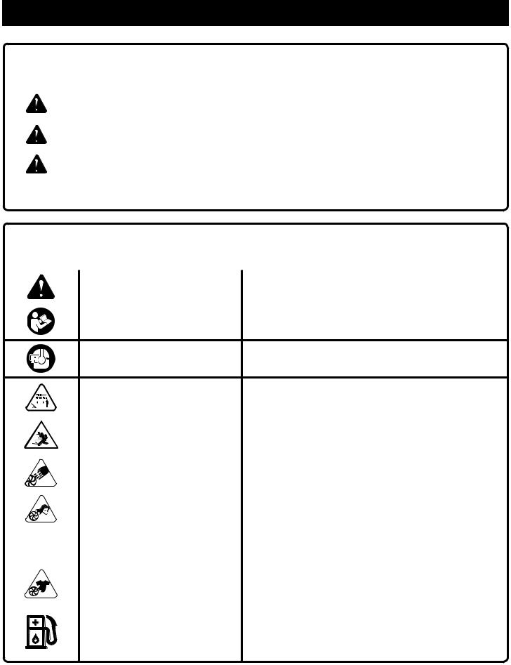
SYMBOLS
The following signal words and meanings are intended to explain the levels of risk associated with this product.
SYMBOL |
SIGNAL |
MEANING |
|
|
|
|
DANGER: |
Indicates an imminently hazardous situation, which, if not avoided, will result |
|
in death or serious injury. |
|
|
|
|
|
|
|
|
WARNING: |
Indicates a potentially hazardous situation, which, if not avoided, could result |
|
in death or serious injury. |
|
|
|
|
|
|
|
|
CAUTION: |
Indicates a potentially hazardous situation, which, if not avoided, may result in |
|
minor or moderate injury. |
|
|
|
|
|
|
|
|
CAUTION: |
(Without Safety Alert Symbol) Indicates a situation that may result in property |
|
damage. |
|
|
|
Some of the following symbols may be used on this product. Please study them and learn their meaning. Proper interpretation of these symbols will allow you to operate the product better and safer.
SYMBOL |
NAME |
EXPLANATION |
|
Safety Alert Symbol |
Indicates a potential personal injury hazard. |
|
|
|
|
Read Operator’s Manual |
To reduce the risk of injury, user must read and understand |
|
operator’s manual before using this product. |
|
|
|
Always wear eye protection with side shields marked to Eye and Hearing Protection comply with ANSI Z87.1 as well as hearing protection when
operating this equipment.
|
|
|
Keep Bystanders Away |
Keep all bystanders at least 50 ft. away. |
|
|
|
|
|
|
|
|
|
|
|
|
|
Ricochet |
Thrown objects can ricochet and result in personal injury or |
|
|
|
property damage. |
|
|
|
|
|
|
|
|
|
|
|
|
|
|
Vacuum Door |
Do not run unit while vacuum door is unsecured. |
|
|
|
|
|
|
|
|
Long Hair |
Risk of long hair being drawn into air inlet. |
|
|
|
|
|
|
|
|
Blower Tubes |
Do not run unit without tubes in place. |
|
|
|
|
|
|
|
|
Loose Clothing |
Risk of loose clothing being drawn into air intake. |
|
|
|
|
|
|
|
|
|
Use unleaded gasoline intended for motor vehicle use with |
|
|
|
Gasoline and Lubricant |
an octane rating of 87 [(R + M) / 2] or higher. This product is |
|
|
|
powered by a 2-cycle engine and requires pre-mixing gasoline |
|
|
|
|
|
|
|
|
|
|
and 2-cycle lubricant. |
5 - English

|
FEATURES |
PRODUCT SPECIFICATIONS |
|
Engine Displacement....................................................................................................................................................... |
26cc |
Air Velocity: |
|
*MPH........................................................................................................................................................................... |
150 |
*CFM............................................................................................................................................................................ |
400 |
Sound Pressure........................................................................................................................................................... |
67dB(A) |
Weight.......................................................................................................................................................................... |
9.5 lbs. |
*Rated per ANSI B175.2
KNOW YOUR BLOWER/VACUUM
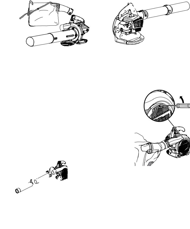
See Figure 1.
The safe use of this product requires an understanding of the information on the tool and in this operator’s manual as well as a knowledge of the project you are attempting. Before use of this product, familiarize yourself with all operating features and safety rules.
BLOWER TUBE AND NOZZLES
The blower tube and nozzles can be assembled and installed on the blower without using any tools.
ENGINE
The blower has a powerful 26cc engine with sufficient power to handle tough blowing and vacuuming jobs.
SWEEPER NOZZLE
The sweeper nozzle allows for more area to be covered during blower operation.
CRUISE CONTROL LEVER/THROTTLE LOCK
The cruise control lever/throttle lock feature allows the user to operate the blower without holding the throttle trigger.
To slow the engine, simply push the cruise control lever/ throttle lock forward.
THROTTLE TRIGGER
The blower can be operated at any speed between idle and full throttle.
VACUUM/MULCHER
Converting the blower to a vacuum/mulcher is simple and can be done using a flat head screwdriver.
VACUUM BAG
The vacuum bag attaches to the blower easily by using the vacuum bag adaptor.
VACUUM HANDLE
This feature allows user to perform vacuuming duties comfortably.
VACUUM TUBES
The vacuum tubes can be installed on the blower using a flat head screwdriver.
TOOLS NEEDED
The following tool (not included or drawn to scale) is needed for assembly:
See Figure 2.
Flat Head Screwdriver
ASSEMBLY
UNPACKING
This product requires assembly.
Carefully remove the product and any accessories from the box. Make sure that all items listed in the packing list are included.
WARNING:
Do not use this product if any parts on the Packing List are already assembled to your product when you unpack it. Parts on this list are not assembled to the product by the manufacturer and require customer installation. Use of a product that may have been improperly assembled could result in serious personal injury.
6 - English

ASSEMBLY
Inspect the product carefully to make sure no breakage or damage occurred during shipping.
Do not discard the packing material until you have carefully inspected and satisfactorily operated the product.
If any parts are damaged or missing, please call 1-800-860-4050 for assistance.
PACKING LIST
Blower
Upper Blower Tube Sweeper Nozzle
Upper and Lower Vacuum Tubes Vacuum Tube Screws (2) Vacuum Bag
Vacuum Bag Adaptor 2-Cycle Engine Lubricant Operator’s Manual
NOTE: Read and remove all hang tags and store with your Operator’s Manual.
INSTALLING THE VACUUM BAG
See Figures 5 - 6.
Remove the nozzle and upper blower tube from the blower by twisting and removing from blower housing outlet.
Unzip the vacuum bag and push the vacuum bag adaptor through the opening opposite the zipper as shown. The wider end of the adaptor will remain on the inside of the vacuum bag when installed properly.
Align the raised slots on the vacuum bag adaptor with the raised locking tabs on the blower housing outlet. Push the vacuum bag adaptor onto the housing and twist to lock into place.
Rotate the vacuum bag until the shoulder strap is upright.
Make sure the vacuum bag is zipped and closed before starting the unit.
INSTALLING THE VACUUM TUBES
See Figures 7 - 8.
WARNING: |
WARNING: |
If any parts are damaged or missing do not operate this product until the parts are replaced. Use of the product with damaged or missing parts could result in possible serious personal injury.
 WARNING:
Do not attempt to modify this product or create accessories not recommended for use with this product. Any such alteration or modification is misuse and could result in a hazardous condition leading to possible serious personal injury.
WARNING:
To prevent accidental starting that could cause serious personal injury, always disconnect the engine spark plug wire from the spark plug when assembling parts.
ASSEMBLING THE BLOWER TUBES
See Figures 3 - 4.
Align raised tabs on blower housing outlet to the slots on upper blower tube; slide together and tighten securely by twisting. Check tightness after initial use and retighten if needed.
Attach sweeper nozzle to upper blower tube by aligning raised tabs on upper blower tube; slide together and tighten securely by twisting. Check tightness after initial use and retighten if needed.
To remove the tubes, rotate the tubes to unlock them and remove from the blower housing outlet.
Contact with rotating impeller blades could result in serious personal injury. Always stop the engine and ensure impeller blades have stopped rotating before opening the vacuum door or installing/changing tubes. Do not put hands or any other object into the vacuum tubes while they are installed on the unit.
To install the vacuum tubes:
Secure the upper and lower vacuum tubes together by aligning the raised locking tabs with the raised slots.
Tap tube assembly on ground until the screw holes in lower tube are in the raised slot of the upper tube. Secure with supplied screws.
Depress door tab using a flathead screwdriver and open vacuum inlet door.
Align screw mounts on vacuum opening with screws on vacuum tube assembly.
Turning clockwise, tighten screws on upper vacuum tube to secure to blower housing.
To remove the vacuum tubes:
Loosen screws of the upper vacuum tube by turning counterclockwise.
Remove the vacuum tube assembly from the blower housing.
Close the vacuum inlet cover door securely.
7 - English
OPERATION
WARNING:
Do not allow familiarity with this product to make you careless. Remember that a careless fraction of a second is sufficient to inflict serious injury.
WARNING:
Always wear eye protection with side shields marked to comply with ANSI Z87.1, along with hearing protection. Failure to do so could result in objects being thrown into your eyes and other possible serious injuries.
WARNING:
Operation of this equipment may create sparks that can start fires around dry vegetation. A spark arrestor may be required. The operator should contact local fire agencies for laws or regulations relating to fire prevention requirements.
APPLICATIONS
You may use this product for the purposes listed below:
Clearing leaves and other debris from your lawn
Keeping decks and driveways free from leaves and other forms of debris
Vacuuming leaves from your lawn
FUELING AND REFUELING
FUEL MIXTURE
This product is powered by a 2-cycle engine and requires pre-mixing gasoline and 2-cycle lubricant. Pre-mix unleaded gasoline and 2-cycle engine lubricant in a clean container approved for gasoline. DO NOT mix quantities larger than usable in a 30-day period.
Recommended fuel: This engine is certified to operate on unleaded gasoline intended for automotive use.
NOTE: We recommend you use Homelite premium 2-cycle lubricant, PowerCare 2-cycle lubricant (6.4 oz. or 16 oz.), or an equivalent high-quality synthetic 2-cycle lubricant in this product. Mix at 2.6 oz. per gallon (US).
Do not use automotive lubricant or 2-cycle outboard lubricant.
HIGH QUALITY 2-CYCLE ENGINE LUBRICANT
|
GASOLINE |
LUBRICANT |
|
|
|
1.0 gal. (US) (3.8 liter) |
2.6 oz. (76 ml) |
|
2.5 gal. (US) (9.5 liter) |
6.4 oz. (189 ml) |
|
FILLING THE TANK
Clean the surface around the fuel cap to prevent contamination.
Loosen the fuel cap slowly by turning counterclockwise.
Pour the fuel mixture carefully into the tank.
Clean and inspect the fuel cap gasket before replacing the fuel cap.
Replace the fuel cap and tighten it by turning it clockwise.
Wipe spilled fuel from the product.
Move at least 30 ft. away from refueling area before starting the product.
NOTE: It is normal for smoke to be emitted from a new engine during first use.
 WARNING:
Always shut off engine before fueling. Never add fuel to a machine with a running or hot engine. Move at least 30 ft. from refueling site before starting engine. Do not smoke and stay away from open flames and sparks. Failure to safely handle fuel could result in serious personal injury.
OXYGENATED FUELS
NOTICE: DO NOT USE E15 OR E85 FUEL (OR FUEL CONTAINING GREATER THAN 10% ETHANOL) IN THIS PRODUCT. IT IS A VIOLATION OF FEDERAL LAW AND WILL DAMAGE THE UNIT AND VOID YOUR WARRANTY.
NOTE: Fuel system damage or performance problems resulting from the use of an oxygenated fuel containing more than the percentages of oxygenates stated below are not covered under warranty.
Ethanol. Gasoline containing up to 10% ethanol by volume (commonly referred to as E10) is acceptable. E15 and E85 are not.
STARTING AND STOPPING
See Figure 9.
Blower should be on a flat, bare surface for starting.
Slowly press the primer bulb 10 times.
NOTE: After the 10th press, fuel should be visible in the primer bulb. If it is not, continue to press the primer until you see fuel in the bulb.
Set the choke lever to the FULL CHOKE position.
Lock cruise control lever/throttle lock.
Pull starter grip and rope sharply until engine attempts to run. Do not pull the starter grip more than four (4) times.
Set the choke lever to the HALF CHOKE position.
Pull the starter grip and rope until the engine runs.
NOTE: If the engine does not start, return to the FULL CHOKE position and repeat the steps that follow.
Allow the engine to run for 15 seconds, then set the choke lever to the RUN position.
8 - English
OPERATION
TO STOP THE ENGINE:
To stop the engine, depress and hold the STOP switch to the stop position “  ”.
”.
HOT RESTART OF THE ENGINE:
Set the choke lever to the RUN position.
Lock cruise control lever/throttle lock.
Pull the starter grip and rope until the engine runs.
IF ASSISTANCE IS REQUIRED STARTING THIS PRODUCT:
Do not return this product to the retail store where it was purchased. Please call our Customer Service Department for any issues you may have.
For Help Call: 1-800-860-4050
OPERATING THE BLOWER
See Figures 10 - 11.
 WARNING:
Never run the unit without the blower tubes installed or the vacuum door securely closed. Use of an improperly assembled unit could result in serious personal injury.
Start the blower. Refer to Starting and Stopping earlier in this manual. Hold the blower with the upper handle in your right hand.
 WARNING:
Always hold the blower away from your body with the handle in your right hand when operating as a blower, keeping clearance between your body and the product. The muffler side of the blower should be away from your body. Any contact with the housing can result in burns and/or other serious personal injury.
Operate blower at the lowest possible throttle speed to do the job.
Check your equipment before operation, especially the muffler, air intakes, and air filters.
Use rakes and brooms to loosen debris before blowing.
In dusty conditions, slightly dampen surfaces when water is available.
Watch out for children, pets, open windows, or freshly washed cars, and blow debris safely away.
Hold blower, as shown in Figure 10, so the air stream can work close to the ground.
After using blowers or other equipment, CLEAN UP! Dispose of debris properly.
Use the sweeper nozzle for the everyday blowing operation. This nozzle allows for more area to be covered during the blowing operation.
CRUISE CONTROL LEVER/THROTTLE LOCK
See Figure 12.
The cruise control lever/throttle lock can be used to operate the blower without holding the throttle trigger.
To engage, pull cruise control lever/throttle lock back towards user, and stop at the desired throttle setting.
To release, push cruise control lever/throttle lock all the way towards the front of unit.
VACUUM OPERATION
See Figure 13.
 WARNING:
Never run the unit without the vacuum tubes and vacuum bag installed. Use of an improperly assembled unit could result in serious personal injury.
WARNING: |
WARNING: |
Do not place blower on top of or near loose debris or gravel. Debris may be sucked into blower intake vent resulting in possible damage to the unit and could result in serious personal injury.
To keep from scattering debris, blow around the outer edges of a debris pile. Never blow directly into the center of a pile.
Operate power equipment at reasonable hours only - not early in the morning or late at night when people might be disturbed. Comply with the times listed in local ordinances.
To reduce sound levels, limit the number of pieces of equipment used at any one time.
Conserve water by using power blowers instead of hoses for many lawn and garden applications, including areas such as gutters, screens, patios, grills, porches, and gardens.
Keep the muffler and all hot surfaces of the blower/ vacuum away from your body. Failure to do so could result in possible serious personal injury.
Install the vacuum tubes and the bag. Refer to the Assembly section earlier in this manual.
Start the blower. Refer to Starting and Stopping earlier in this manual.
Place the vacuum bag strap over your right shoulder. Hold the upper handle in your left hand and the vacuum handle in your right hand.
Move the blower/vacuum from side to side along outer edge of the debris. To avoid clogging, do not place the vacuum tube directly into the debris pile.
Hold the engine higher than the inlet end of the vacuum tube.
9 - English

OPERATION
Always point vacuum tube downhill when working on a hillside.
To avoid serious injury to the operator or damage to the unit, do not pick up rocks, metal, broken glass, bottles, or other similar objects.
If the vacuum tubes should clog, stop the engine , ensure impeller blades have stopped spinning, and disconnect the spark plug wire before cleaning out the obstruction.
Remove the vacuum tubes and clear the debris from the blower fan housing. Remove the bag and clear the tube. A small rod or stick may be required to clear the entire tube length. Ensure that all debris has been cleared before reassembling the vacuum tubes.
MAINTENANCE
 WARNING:
When servicing, use only identical replacement parts. Use of any other parts could create a hazard or cause product damage.
 WARNING:
Always wear eye protection with side shields marked to comply with ANSI Z87.1, along with hearing protection. Failure to do so could result in objects being thrown into your eyes and other possible serious injuries.
 WARNING:
Before inspecting, cleaning, or servicing the machine, shut off engine, wait for all moving parts to stop, and disconnect spark plug wire and move it away from spark plug. Failure to follow these instructions can result in serious personal injury or property damage.
GENERAL MAINTENANCE
Avoid using solvents when cleaning plastic parts. Most plastics are susceptible to damage from various types of commercial solvents and may be damaged by their use. Use clean cloths to remove dirt, dust, lubricant, grease, etc.
 WARNING:
Do not at any time let brake fluids, gasoline, petroleumbased products, penetrating lubricants, etc., come in contact with plastic parts. Chemicals can damage, weaken or destroy plastic which could result in serious personal injury.
You can often make adjustments and repairs described here. For other repairs, have the blower/vacuum serviced by an authorized service dealer.
CLEANING THE AIR FILTER
See Figure 14 - 15.
For proper performance and long life, keep air filter clean.
Remove the air filter cover by turning the dial counterclockwise while gently pulling on the cover.
Rinse filter with clean water.
Gently squeeze filter until excess water is removed. Replace filter.
Place the air filter cover back on the unit. Turn dial clockwise until cover is secure.
CLEANING THE EXHAUST PORT, MUFFLER AND SPARK ARRESTOR
NOTE: Depending on the type of fuel used, the type and amount of lubricant used, and/or your operating conditions, the exhaust port, muffler, and/or spark arrestor screen may become blocked with carbon deposits. If you notice a power loss with your gas powered tool, you may need to remove these deposits to restore performance. We highly recommend that only qualified service technicians perform this service.
The spark arrestor must be cleaned or replaced every 50 hours or yearly to ensure proper performance of your product. Spark arrestors may be in different locations depending on the model purchased. Please contact your nearest service dealer for the location of the spark arrestor for your model.
 WARNING:
Never run the blower without the spark arrestor in place. Failure to do so could result in a fire that could cause serious personal injury.
VACUUM BAG
A dirty bag will reduce performance. To clean the bag, turn it inside out and shake. Wash the bag in soapy water at least once a year. To obtain a replacement bag, see How to Obtain Replacement Parts on the back page of this manual.
10 - English

MAINTENANCE
FUEL CAP
 WARNING:
Check for fuel leaks. A leaking fuel cap is a fire hazard and must be replaced immediately. If you find any leaks, correct the problem before using the product. Failure to do so could result in a fire that could cause serious personal injury.
The fuel cap contains a non-serviceable filter and a check valve. A clogged fuel filter will cause poor engine performance. If performance improves when the fuel cap is loosened, check valve may be faulty or filter clogged. Replace fuel cap if required.
SPARK PLUG REPLACEMENT
This engine uses a Ryobi AC00160 or Champion RCJ-6Y spark plug with .025 in. electrode gap. Use an exact replacement and replace annually.
STORING THE PRODUCT
Clean all foreign material from the product. Store idle unit indoors in a dry, well-ventilated area that is inaccessible to children. Keep away from corrosive agents such as garden chemicals and de-icing salts.
Abide by all ISO and local regulations for the safe storage and handling of gasoline.
When storing 1 month or longer:
Drain all fuel from tank into a container approved for gasoline. Run engine until it stops.
HIGH ALTITUDE ENGINE OPERATION
Please have an authorized service center adjust this engine if it is to be run above 2000 feet. Failure to do so may result in poor engine performance and increased emissions. An engine adjusted for high altitudes can not be run at 2000 feet or lower. In doing so, the engine will overheat and cause serious engine damage. Please have an authorized service center restore high altitude modified engines to the original factory specification before operating below 2000 feet.
THIS PRODUCT WAS MANUFACTURED WITH A CATALYST MUFFLER
Congratulations! You have made an investment toward protecting the environment. In order to maintain this product’s original emission level, please refer to the maintenance section below.
MAINTENANCE SCHEDULE
|
Inspect |
Clean |
Replace |
Replace |
Maintenance |
Before |
Every |
Every 25 Hours |
Every |
Part |
Each Use |
5 Hours |
or Yearly |
50 Hours |
*CATALYTIC MUFFLER ASSEMBLY.................................................................................................................. |
|
|
X |
|
SPARK SCREEN................................................................................................................................................ |
|
|
|
X |
*AIR FILTER ASSY |
|
|
|
|
includes: |
|
|
|
|
Filter..................................................................................... |
|
X |
|
|
*CARBURETOR ASSY |
|
|
|
|
includes: |
|
|
|
|
Gaskets......................................... |
X |
|
|
|
*FUEL TANK ASSY |
|
|
|
|
includes: |
|
|
|
|
Fuel Lines...................................... |
X |
|
|
|
Fuel Cap....................................... |
X |
|
|
|
Fuel Filter................................................................................................................... |
X |
*IGNITION ASSY |
|
includes: |
|
Spark Plug................................................................................................................. |
X |
*NOTICE: THE USE OF EMISSION CONTROL COMPONENTS OTHER THAN THOSE DESIGNED FOR THIS UNIT IS A VIOLATION OF FEDERAL LAW.
11 - English
 Loading...