


 Loading...
C231
SERVICE MANUAL
RICOH GROUP COMPANIES |
PN: RCSMC231 |

®
®
®
MANUAL SERVICE
C231
RICOH GROUP COMPANIES

C231
SERVICE MANUAL
PN:RCSMC231

WARNING
The Service Manual contains information regarding service techniques, procedures, processes and spare parts of office equipment distributed by Ricoh Corporation. Users of this manual should be either service trained or certified by successfully completing a Ricoh Technical Training Program.
Untrained and uncertified users utilizing information contained in this service manual to repair or modify Ricoh equipment risk personal injury, damage to property. or loss of warranty protection.
Ricoh Corporation
LEGEND
PRODUCT CODE |
|
COMPANY |
|
|
|
RICOH |
|
SAVIN |
GESTETNER |
C231 |
JP1030 |
|
3150DNP |
5306L |
|
|
|
|
|
|
|
|
|
|
DOCUMENTATION HISTORY
REV. NO. |
DATE |
COMMENTS |
* |
7/98 |
Original Printing |
|
|
|
C231
TABLE OF CONTENTS
OVERALL INFORMATION............................................................... |
1-1 |
|
1.1 |
SPECIFICATION ...................................................................................... |
1-1 |
1.2 |
GUIDE TO COMPONENTS AND THEIR FUNCTION .............................. |
1-5 |
|
1.2.1 MACHINE EXTERIOR ..................................................................... |
1-5 |
|
1.2.2 MACHINE INTERIOR ...................................................................... |
1-6 |
|
1.2.3 OPERATION PANEL ....................................................................... |
1-7 |
|
Keys ..................................................................................................... |
1-7 |
|
Indicators ............................................................................................. |
1-9 |
1.3 |
PRINTING PROCESS ............................................................................ |
1-10 |
1.4 |
MECHANICAL COMPONENT LAYOUT................................................. |
1-11 |
1.5 |
ELECTRICAL COMPONENT LAYOUT .................................................. |
1-12 |
|
1.5.1 ADF................................................................................................ |
1-12 |
|
1.5.2 MAIN BODY................................................................................... |
1-13 |
|
Boards................................................................................................ |
1-14 |
|
Motors ................................................................................................ |
1-14 |
|
Solenoids ........................................................................................... |
1-15 |
|
Switches............................................................................................. |
1-15 |
|
Sensors.............................................................................................. |
1-15 |
|
Counters ............................................................................................ |
1-16 |
|
Others ................................................................................................ |
1-16 |
1.6 |
DRIVE LAYOUT ..................................................................................... |
1-17 |
DETAILED SECTION DESCRIPTIONS............................................ |
2-1 |
2.1 SCANNER AND OPTICS ......................................................................... |
2-1 |
2.1.1 BOOK SCANNER OVERVIEW........................................................ |
2-1 |
2.1.2 ADF OVERVIEW ............................................................................. |
2-2 |
2.1.3 CONTACT IMAGE SENSOR ........................................................... |
2-4 |
2.1.4 DRIVE MECHANISM ....................................................................... |
2-5 |
Book Scanner....................................................................................... |
2-5 |
ADF...................................................................................................... |
2-6 |
2.1.5 PICK-UP AND FEED (ADF)............................................................. |
2-7 |
2.1.6 SEPARATION MECHANISM (ADF) ................................................ |
2-8 |
2.1.7 ERROR CONDITIONS .................................................................... |
2-9 |
Book Scanner....................................................................................... |
2-9 |
ADF...................................................................................................... |
2-9 |
2.2 IMAGE-PROCESSING ........................................................................... |
2-10 |
2.2.1 OVERVIEW ................................................................................... |
2-10 |
2.2.2 A/D CONVERSION PROCESSING ............................................... |
2-11 |
Shading Distortion Correction ............................................................ |
2-11 |
Original Background Correction ......................................................... |
2-12 |
Peak Hold .......................................................................................... |
2-12 |
SM |
i |
C231 |
2.2.3 BINARY PROCESSING................................................................. |
2-13 |
Data Compensation Processing......................................................... |
2-13 |
MTF Correction .................................................................................. |
2-14 |
Binary Processing in Letter/Photo Mode ............................................ |
2-14 |
Error Diffusion .................................................................................... |
2-15 |
2.2.4 MAIN SCAN MAGNIFICATION...................................................... |
2-16 |
2.2.5 IMAGE POSITION ADJUSTMENT IN THE MAIN |
|
SCAN DIRECTION ........................................................................ |
2-17 |
2.2.6 PASTE SHADOW ERASE MODE ................................................. |
2-17 |
2.2.7 THERMAL HEAD........................................................................... |
2-18 |
Specifications ..................................................................................... |
2-18 |
Thermal Head Control........................................................................ |
2-18 |
Thermal Head Protection ................................................................... |
2-18 |
Remarks for Handling the Thermal Head........................................... |
2-19 |
2.3 MASTER EJECT .................................................................................... |
2-20 |
2.3.1 OVERALL ...................................................................................... |
2-20 |
2.3.2 MASTER CLAMPER OPEN MECHANISM.................................... |
2-21 |
Drum Position Lock Mechanism......................................................... |
2-21 |
2.3.3 MASTER EJECT ROLLER MECHANISM ..................................... |
2-22 |
2.3.4 PRESSURE PLATE MECHANISM ................................................ |
2-23 |
2.4 MASTER FEED ...................................................................................... |
2-24 |
2.4.1 OVERALL ...................................................................................... |
2-24 |
2.4.2 MASTER FEED MECHANISM....................................................... |
2-25 |
2.4.3 MASTER CLAMPER OPERATION AND TENSION ROLLER |
|
RELEASE MECHANISM ............................................................... |
2-26 |
2.4.4 CUTTER MECHANISM ................................................................. |
2-27 |
2.5 DRUM ..................................................................................................... |
2-28 |
2.5.1 OVERALL ...................................................................................... |
2-28 |
2.5.2 DRUM DRIVE MECHANISM ......................................................... |
2-29 |
2.5.3 INK SUPPLY MECHANISM ........................................................... |
2-30 |
2.5.4 INK ROLLER MECHANISM........................................................... |
2-31 |
2.5.5 INK SUPPLY CONTROL ............................................................... |
2-32 |
2.5.6 DETECTION OF MASTERS ON THE DRUM................................ |
2-33 |
2.6 PAPER FEED ......................................................................................... |
2-34 |
2.6.1 OVERALL ...................................................................................... |
2-34 |
2.6.2 PAPER FEED MECHANISM ......................................................... |
2-35 |
2.6.3 PAPER FEED/SEPARATION PRESSURE ADJUSTMENT |
|
MECHANISM................................................................................. |
2-36 |
2.6.4 REGISTRATION ROLLER MECHANISM...................................... |
2-37 |
Registration Roller Drive .................................................................... |
2-37 |
Registration Roller Up/Down Mechanism........................................... |
2-38 |
2.6.5 PRINTING PRESSURE MECHANISM .......................................... |
2-39 |
2.6.6 PAPER TABLE MECHANISM........................................................ |
2-40 |
Table Up and Down Mechanism ........................................................ |
2-40 |
Paper End Detection Mechanism....................................................... |
2-40 |
Paper Table Side Fence Mechanism ................................................. |
2-41 |
Paper Table Side-to-Side Shift Mechanism ....................................... |
2-41 |
Side Fence Friction Pads ................................................................... |
2-42 |
C231 |
ii |
SM |
2.7 PAPER DELIVERY................................................................................. |
2-43 |
2.7.1 OVERALL ...................................................................................... |
2-43 |
2.7.2 PAPER DELIVERY UNIT DRIVE MECHANISM ............................ |
2-44 |
2.7.3 PAPER SEPARATION FROM DRUM ........................................... |
2-45 |
2.7.4 EXIT PAWL DRIVE MECHANISM ................................................. |
2-46 |
2.8 ERROR DETECTION ............................................................................. |
2-47 |
2.8.1 ORIGINAL JAM DETECTION ........................................................ |
2-47 |
2.8.2 MASTER EJECT JAM DETECTION.............................................. |
2-47 |
2.8.3 MASTER FEED JAM DETECTION................................................ |
2-48 |
2.8.4 PAPER FEED JAM DETECTION .................................................. |
2-49 |
INSTALLATION................................................................................ |
3-1 |
3.1 INSTALLATION REQUIREMENTS .......................................................... |
3-1 |
3.1.1 OPTIMUM ENVIRONMENTAL CONDITION ................................... |
3-1 |
3.1.2 ENVIRONMENTS TO AVOID .......................................................... |
3-1 |
3.1.3 POWER CONNECTION .................................................................. |
3-1 |
3.1.4 ACCESS TO MACHINE................................................................... |
3-2 |
3.2 INSTALLATION PROCEDURE ................................................................ |
3-3 |
3.2.1 MAIN BODY..................................................................................... |
3-3 |
Accessory Check ................................................................................. |
3-3 |
Installation Procedure .......................................................................... |
3-4 |
3.2.2 AUTO DOCUMENT FEEDER (OPTION)......................................... |
3-9 |
Accessory Check ................................................................................. |
3-9 |
Installation Procedure ........................................................................ |
3-10 |
3.2.3 TAPE MARKER (OPTION) ............................................................ |
3-14 |
Accessory Check ............................................................................... |
3-14 |
Installation Procedure - For C231 - .................................................... |
3-15 |
3.2.4 COLOR DRUM (OPTION) ............................................................. |
3-17 |
3.2.5 INTERFACE BOARD (OPTION).................................................... |
3-18 |
Accessory Check ............................................................................... |
3-18 |
Installation Procedure ........................................................................ |
3-18 |
SERVICE TABLES........................................................................... |
4-1 |
|
4.1 SERVICE REMARKS ............................................................................... |
4-1 |
|
4.1.1 MASTER FEED SECTION............................................................... |
4-1 |
|
1. |
Thermal Head Installation ................................................................ |
4-1 |
2. |
Thermal Head Voltage Adjustment .................................................. |
4-1 |
4.1.2 PAPER FEED SECTION ................................................................. |
4-1 |
|
1. |
Friction Pad ...................................................................................... |
4-1 |
2. |
Paper Feed Roller and Paper Separation Roller .............................. |
4-1 |
3. |
Paper Guide Plate Position for Registration Roller........................... |
4-1 |
4.1.3 DRUM AND DRUM DRIVE SECTION ............................................. |
4-2 |
|
1. |
Main Motor ....................................................................................... |
4-2 |
2. |
Doctor Roller .................................................................................... |
4-2 |
3. |
Drum Master Clamper...................................................................... |
4-2 |
SM |
iii |
C231 |
4. Ink Roller Unit................................................................................... |
4-2 |
5. Ink Pump.......................................................................................... |
4-2 |
4.1.4 PAPER DELIVERY SECTION ......................................................... |
4-3 |
1. Exit Pawl .......................................................................................... |
4-3 |
4.1.5 ELECTRICAL COMPONENTS ........................................................ |
4-3 |
1. Main Processing Unit (MPU) 1 ......................................................... |
4-3 |
2. Main Processing Unit (MPU) 2 ......................................................... |
4-3 |
3. Power Supply Unit............................................................................ |
4-3 |
4. Sensor Adjustments ......................................................................... |
4-3 |
4.2 DIP SW, LED, VR, TP, AND FUSE TABLES............................................ |
4-4 |
4.2.1 TEST POINTS ................................................................................. |
4-4 |
MPU ..................................................................................................... |
4-4 |
4.2.2 POTENTIOMETERS........................................................................ |
4-4 |
MPU ..................................................................................................... |
4-4 |
Power Supply Unit................................................................................ |
4-4 |
4.2.3 LED'S............................................................................................... |
4-4 |
4.2.4 FUSES............................................................................................. |
4-5 |
MPU ..................................................................................................... |
4-5 |
PSU...................................................................................................... |
4-5 |
4.3 SERVICE CALL CODES .......................................................................... |
4-6 |
4.4 SERVICE PROGRAM MODE................................................................... |
4-8 |
4.4.1 ACCESS PROCEDURE .................................................................. |
4-8 |
Service Program Mode Access Procedure (For Engineers)................. |
4-8 |
Service Program Mode Access Procedure (For Users) ....................... |
4-9 |
Change Adjustment Values or Modes................................................ |
4-10 |
4.4.2 SERVICE PROGRAM TABLE ....................................................... |
4-11 |
Remarks............................................................................................. |
4-20 |
4.4.3 INPUT/OUTPUT CHECK MODE ................................................... |
4-23 |
Input/Output Check Mode Access Procedure .................................... |
4-23 |
Input Check Table .............................................................................. |
4-24 |
Output Check Table ........................................................................... |
4-26 |
4.5 TEST PATTERN IMAGE MODE............................................................. |
4-28 |
4.6 USER CODE MODE............................................................................... |
4-29 |
PREVENTIVE MAINTENANCE ........................................................ |
5-1 |
|
5.1 |
MAINTENANCE TABLE ........................................................................... |
5-1 |
REPLACEMENT AND ADJUSTMENT............................................. |
6-1 |
|
6.1 |
EXTERIOR COVER REMOVAL ............................................................... |
6-1 |
|
6.1.1 ADF.................................................................................................. |
6-1 |
|
6.1.2 OPERATION PANEL ....................................................................... |
6-2 |
|
6.1.3 PLATEN COVER AND UPPER COVERS ....................................... |
6-3 |
|
6.1.4 TOP COVER AND EXPOSURE GLASS ......................................... |
6-3 |
|
6.1.5 OTHER COVERS ............................................................................ |
6-4 |
C231 |
iv |
SM |
6.2 COPY IMAGE ADJUSTMENT .................................................................. |
6-6 |
6.2.1 LEADING EDGE REGISTRATION ADJUSTMENT ......................... |
6-6 |
6.2.2 SIDE-TO-SIDE REGISTRAION ADJUSTMENT .............................. |
6-7 |
6.2.3 VERTICAL MAGNIFICATION ADJUSTMENT ................................. |
6-8 |
6.2.4 LEADING EDGE BLANK MARGIN ADJUSTMENT ......................... |
6-9 |
6.3 MPU REPLACEMENT ............................................................................ |
6-10 |
6.4 ORIGINAL FEED SECTION ................................................................... |
6-11 |
6.4.1 ADF ROLLER ASSSEMBLY.......................................................... |
6-11 |
6.4.2 PICK-UP ROLLER ......................................................................... |
6-11 |
6.4.3 FEED ROLLER .............................................................................. |
6-12 |
6.4.4 SEPARATION ROLLER ................................................................ |
6-12 |
6.4.5 ADF MOTOR AND COVERS......................................................... |
6-13 |
6.4.6 R0 AND R1 ROLLERS .................................................................. |
6-13 |
6.4.7 R2 ROLLER................................................................................... |
6-14 |
6.4.8 DOCUMENT SENSOR .................................................................. |
6-15 |
6.4.9 SCAN LINE SENSOR.................................................................... |
6-15 |
6.4.10 COVER SENSORS...................................................................... |
6-16 |
6.5 MASTER FEED SECTION ..................................................................... |
6-17 |
6.5.1 MASTER MAKING UNIT REMOVAL ............................................. |
6-17 |
6.5.2 THERMAL HEAD REMOVAL ........................................................ |
6-19 |
Remarks for thermal head installation................................................ |
6-20 |
6.5.3 THERMAL HEAD VOLTAGE ADJUSTMENT ................................ |
6-21 |
6.5.4 MASTER END SENSOR ADJUSTMENT ...................................... |
6-23 |
6.6 MASTER EJECT SECTION.................................................................... |
6-24 |
6.6.1 MASTER EJECT UNIT REMOVAL................................................ |
6-24 |
6.7 PAPER FEED SECTION ........................................................................ |
6-25 |
6.7.1 PAPER FEED ROLLER, PICK-UP ROLLER, |
|
AND FRICTION PAD.................................................................... |
6-25 |
6.7.2 PAPER SEPARATION PRESSURE ADJUSTMENT ..................... |
6-26 |
6.7.3 PAPER FEED PRESSURE ADJUSTMENT .................................. |
6-27 |
6.7.4 REGISTRATION ROLLER CLEARANCE ADJUSTMENT............. |
6-28 |
6.8 PRINTING SECTION.............................................................................. |
6-29 |
6.8.1 PRESS ROLLER REMOVAL ......................................................... |
6-29 |
6.8.2 PRESS ROLLER LOCK LEVER ADJUSTMENT ........................... |
6-30 |
6.8.3 PRINTING PRESSURE ADJUSTMENT ........................................ |
6-32 |
6.9 DRUM AND DRIVE SECTION................................................................ |
6-33 |
6.9.1 DRUM CLOTH SCREEN REMOVAL............................................. |
6-33 |
Remarks for the cloth screen installation ........................................... |
6-34 |
6.9.2 DRUM MASTER CLAMPER AND METAL SCREEN REMOVAL .. |
6-36 |
Remarks for drum screen installation................................................. |
6-38 |
6.9.3 INK ROLLER UNIT REMOVAL...................................................... |
6-39 |
6.9.4 DOCTOR ROLLER GAP ADJUSTMENT ...................................... |
6-41 |
6.9.5 INK DETECTION ADJUSTMENT .................................................. |
6-43 |
6.9.6 INK PUMP REMOVAL AND PLUNGER |
|
POSITION ADJUSTMENT............................................................. |
6-44 |
6.9.7 MAIN DRIVE TIMING BELT TENSION ADJUSTMENT................. |
6-46 |
6.9.8 MAIN MOTOR PULLEY POSITION ADJUSTMENT...................... |
6-48 |
SM |
v |
C231 |
6.10 PAPER DELIVERY SECTION .............................................................. |
6-49 |
6.10.1 VACUUM UNIT REMOVAL.......................................................... |
6-49 |
6.10.2 DELIVERY BELT/PAPER EXIT SENSOR REMOVAL................. |
6-50 |
6.10.3 VACUUM MOTOR REMOVAL..................................................... |
6-51 |
6.10.4 EXIT PAWL CLEARANCE ADJUSTMENT .................................. |
6-52 |
6.10.5 EXIT PAWL DRIVE TIMING ADJUSTMENT ............................... |
6-53 |
TAPE MARKER C532 |
|
|
SPECIFICATIONS............................................................................ |
7-1 |
|
BASIC OPERATION ........................................................................ |
7-2 |
|
2.1 |
OVERVIEW .............................................................................................. |
7-2 |
2.2 |
DRIVE AND CUTTING MECHANISM....................................................... |
7-3 |
2.3 |
MANUAL CUT .......................................................................................... |
7-4 |
REPLACEMENT AND ADJUSTMENT............................................. |
7-5 |
|
3.1 |
CUTTER REPLACEMENT ....................................................................... |
7-5 |
3.2 |
CUTTER HOME POSITION SENSOR REPLACEMENT.......................... |
7-6 |
3.3 |
TAPE CUT LENGTH ADJUSTMENT ....................................................... |
7-7 |
PRIPORT CONTROLLER USER’S GUIDE...................................... |
8-1 |
|
POINT TO POINT DIAGRAM |
|
|
C231 |
vi |
SM |

IMPORTANT SAFETY NOTICES
PREVENTION OF PHYSICAL INJURY
1.Before disassembling or assembling parts of the printer and peripherals, make sure that the power cord is unplugged.
2.The wall outlet should be near the printer and easily accessible.
3.If any adjustment or operation check has to be made with exterior covers off or open while the main switch is turned on, keep hands away from electrified or mechanically driven components.
HEALTH SAFETY CONDITIONS
1.If you get ink in your eyes by accident, try to remove it with eye drops or flush with water as first aid. If unsuccessful, get medical attention.
2.If you ingest ink by accident, induce vomiting by sticking a finger down your throat or by giving soapy or strong salty water to drink.
OBSERVANCE OF ELECTRICAL SAFETY STANDARDS
1.The printer and its peripherals must be installed and maintained by a customer service representative who has completed the training course on those models.
CAUTION
The RAM has a lithium battery which can explode if handled incorrectly. Replace only with the same type of RAM. Do not recharge or burn this battery. Used RAM's must be handled in accordance with local regulations.
ATTENTION
La carte RAM comporte une pile au lithium qui présente un risque d'explosion en cas de mauvaise manipulation. Remplacer la pile uniquement par une carte RAM identique. Ne pas recharger ni brûler cette pile. Les cartes RAM usagées doivent être éliminées conformément aux réglementations locales.
SAFETY AND ECOLOGICAL NOTES FOR DISPOSAL
1.Dispose of replaced parts in accordance with local regulations.
2.Used ink and masters should be disposed of in an environmentally safe manner and in accordance with local regulations.
3.When keeping used lithium batteries (from the main processing units) in order to dispose of them later, do not store more than 100 batteries (from the main processing units) per sealed box. Storing larger numbers or not sealing them apart may lead to chemical reactions and heat build-up.

OVERALL INFORMATION
DETAILED SECTION DESCRIPTIONS
INSTALLATION
SERVICE TABLES
PREVENTIVE MAINTENANCE
REPLACEMENT AND ADJUSTMENT
TAPE MARKER C532
PRIPORT CONTROLLER USER’S GUIDE
TAB |
POSITION 1 |
|
|
|
|
TAB |
POSITION 2 |
|
|
|
|
TAB |
POSITION 3 |
|
|
|
|
TAB |
POSITION 4 |
|
|
|
|
TAB |
POSITION 5 |
|
|
|
|
TAB |
POSITION 6 |
|
|
|
|
TAB |
POSITION 7 |
|
|
|
|
TAB |
POSITION 8 |
|
|
OVERALL
INFORMATION

SPECIFICATION
1. OVERALL INFORMATION
1.1 SPECIFICATION
Configuration: |
Desktop |
|
|
Master Processing: |
Digital with 300 dpi thermal head |
|
|
Scanning (Pixel Density): |
Contact image sensor (300 dpi), with xenon lamp |
||
|
* In Fine mode, 400 dpi in the sub-scanning |
||
|
resolution |
|
|
Printing Process: |
Fully automatic one-drum stencil system |
||
Original Type: |
Sheet/Book |
|
|
In Platen Mode: |
Document size: |
|
|
|
Maximum 257 x 364 mm |
[10.2" x 14.4"] |
|
|
Thickness: Less than 30 mm |
|
|
|
Weight: |
Less than 5 kg |
|
In ADF Mode: |
Document size: |
|
|
|
Maximum 257 x 364 mm |
[10.2" x 14.4"] |
|
|
Minimum 148 x 105 mm |
[5.8" x 4.1"] |
|
|
Document weight: |
|
|
|
50 - 90 g/m2 [13.3 - 23.9 lb] |
|
|
|
(40 - 120 g/m2 [10.6 - 31.9 lb] |
||
|
|
in single sheet feed) |
|
|
ADF capacity: |
|
|
|
30 sheets (using 20 lb or 80 g/m2 paper) |
||
Reproduction Ratios: |
|
Inch version |
Others |
|
Full Size: |
100% |
100% |
|
Reduction: |
65% |
71% |
|
|
74% |
82% |
|
|
77% |
87% |
|
|
93% |
93% |
|
Enlargement: |
121% |
115% |
|
|
129% |
122% |
|
|
155% |
141% |
Image Modes: |
Letter, Photo, Letter/Photo, Fine, Tint |
||
Overall |
Information |
|
|
SM |
1-1 |
C231 |
SPECIFICATION
Printing Area: |
B4 size drum models: |
|
(At 20 °C/ 65 % RH) |
250 mm x 355 mm |
|
|
Legal size drum models: |
|
|
210 mm x 355 mm [8.2" x 13.9"] |
|
|
A4 size drum models: |
|
|
210 mm x 288 mm [8.2" x 11.3"] |
|
Edge Margins: |
Leading edge: |
|
|
5 ± 3 mm (At the "0" position of Image Shift mode) |
|
|
Trailing edge: |
|
|
2 mm |
|
Print Paper Size: |
Minimum: 90 mm x 148 mm [3.6" x 5.9"] |
|
|
Maximum: 267 mm x 390 mm [10.5" x 15.3"] |
|
Print Paper Weight: |
47.1 g/m2 to 157.0 g/m2 [12.5 lb to 41.7 lb] |
|
Printing Speed: |
80, 100, 120 sheets/minute (3 steps) |
|
Master Process Time: |
Platen mode: |
|
|
Less than 28 seconds (A4 paper) |
|
|
ADF mode: |
|
|
Less than 30 seconds (A4 paper) |
|
Master Eject Box Capacity: |
40 masters (Normal conditions) |
|
|
(30 masters at low temperatures) |
|
Side Registration Adjustable |
± 10 mm |
|
Range: |
|
|
Vertical Registration Adjustable |
± 10 mm |
|
Range: |
|
|
Paper Feed Table Capacity: |
1000 sheets (80 g/m2 / 20 lb) |
|
Paper Delivery Table Capacity: |
1000 sheets (80 g/m2/ 20 lb) |
|
Power Source: |
110/120 V, 50/60 Hz: |
2.5 A |
|
220 - 240 V, 50/60 Hz: |
1.5 A |
Maximum Power Consumption: |
250 W |
|
Noise Emission: |
At 80 rpm printing speed: |
71 dB |
(At operation position) |
At 100 rpm printing speed: 72 dB |
|
|
At 120 rpm printing speed: 72 dB |
|
C231 |
1-2 |
SM |
|
SPECIFICATION |
Weight: |
65 kg [143.3 lb] |
|
68 kg [149.9 lb] with ADF |
Dimensions: |
Trays closed: 594 mm x 601 mm x 567 mm |
(Width x Depth x Height) |
With ADF: |
|
594 mm x 601 mm x 617 mm |
|
Trays open: 1187 mm x 601 mm x 567 mm |
|
With ADF: |
|
1187 mm x 601 mm x 617 mm |
Master Type: |
Master for B4 drum |
|
Thermal master roll type: |
|
280 mm width, 125 m/roll |
|
Yield: |
|
260 masters/roll |
|
Max run length per master: |
|
2,000 prints |
|
Master for A4/Legal drum |
|
Thermal master roll type: |
|
240 mm width, 125 m/roll |
|
Yield: |
|
300 masters/roll (A4 drum) |
|
260 masters/roll (Legal drum) |
|
Max run length per master: |
|
2,000 prints |
Master Storage Conditions: |
Temperature: |
|
0 °C to 40 °C |
|
Humidity: |
|
10% to 95% RH |
|
Recommended maximum storage period: |
|
One year after production date |
|
* Avoid locations exposed to direct sunlight. |
Overall |
Information |
|
|
SM |
1-3 |
C231 |
SPECIFICATION
Ink Type
Ink Storage Conditions:
Available Options
600 ml cartridge type
Available colors:
Black, Red, Blue, Green, Brown
Temperature: -5 °C to 40 °C
(Optimum conditions: 15 °C to 25 °C)
Humidity:
10% to 95% RH
(Optimum conditions: 20% to 70% RH)
Recommended maximum storage period:
One year after production date
* Avoid locations exposed to direct sunlight.
•Color Drum
•Document Feeder
•Key Counter
•Tape Marker
•PC Controller
C231 |
1-4 |
SM |

GUIDE TO COMPONENTS AND THEIR FUNCTION
1.2GUIDE TO COMPONENTS AND THEIR FUNCTION
1.2.1 MACHINE EXTERIOR
Overall |
Information |
|
|
1.Front Door
2.Operation Panel
3.Platen Cover
4.Original Table Release Lever
5.Feed Roller Pressure Lever
6.Paper Feed Side Plates
7.Paper Feed Table
Open for access to the inside of the machine.
Operator controls and indicators are located here.
Lower this cover over an original before printing.
Use to open the original table unit when installing the master.
Use to adjust the contact pressure of the paper feed roller according to paper thickness.
Use to prevent paper skew.
Set paper on this table for printing.
8.Side Table Fine Adjusting Use to shift the paper feed table sideways.
Dial
9.Paper Feed Table Down Press to lower the paper feed table. key
10. Behind Cover |
Flip up when you wish to use the keys underneath. |
SM |
1-5 |
C231 |

GUIDE TO COMPONENTS AND THEIR FUNCTION
1.2.2 MACHINE INTERIOR
1. Document Feeder (Option) Originals inserted into the document feeder are individually and automatically fed onto and removed from the exposure glass.
2.Paper Delivery Side Plates Use to align the prints on the paper delivery table.
3.Paper Delivery End Plate Use to align the leading edge of prints.
4. |
Paper Delivery Table |
Completed prints are delivered here. |
5. |
Main Switch |
Use to turn the power on or off. |
6. |
Drum Unit |
The master is wrapped around this unit. |
7. |
Drum Unit Lock Lever |
Lift to unlock and pull out the drum unit. |
8. |
Ink Holder |
Set the ink cartridge in this holder. |
C231 |
1-6 |
SM |
GUIDE TO COMPONENTS AND THEIR FUNCTION
1.2.3 OPERATION PANEL
Keys |
2 |
4 |
|
1 |
3 |
5 |
15 |
6 |
7 |
8 |
9 |
11 |
13 14 |
21 |
|
|
|
10 |
|
12 |
20 |
1.Security key
Press to make prints of confidential documents.
2.Paste Shadow Erase key
Press to erase the shadows on images of pasted originals.
3.Tint key
Press to make prints in grey.
(This is the Tint/Economy key for the China version.)
4.Image Density key
Press to make prints darker or lighter.
5.Check Indicator
This indicator lights when you have selected one or more of the functions accessed by lifting the behind cover and pressing the keys underneath (e. g. Security key, Paste Shadow Erase key etc.). This lets you know whether one or more of these functions is selected, even if the cover is lowered.
6.Skip Feed key
Press to select skip feed printing.
7.Center/Edge Erase key
Press to print book originals that have a solid image on the center or edges.
8.Scroll keys
Press to select size and direction of paper or original for
Center/Edge Erase.
9.Reduce key
Press to reduce the image.
10.Full Size key
Press to make full size prints.
11.Enlarge key
Press to enlarge the image.
12.Economy key
Press to save ink. (This is the
Combine 2 Originals key for the
China version.)
13.Type of Original key
Press to select Letter, Photo, or Letter/Photo mode.
14.Fine key
Press to select fine image mode.
15.Image Position key
Press to shift the image forwards or backwards.
Overall |
Information |
|
|
SM |
1-7 |
C231 |

GUIDE TO COMPONENTS AND THEIR FUNCTION
16 |
17 |
18 |
19 |
|
|
|
|
|
|
|
|
|
|
|
|
|
|
|
|
|
|
|
|
|
|
|
|
|
|
|
|
|
|
|
|
|
|
|
|
|
|
|
|
|
|
|
|
|
|
|
|
|
|
|
|
|
|
|
|
|
|
|
|
|
|
|
|
|
|
|
|
|
|
|
|
|
|
|
|
|
|
|
|
|
|
|
|
|
|
|
|
|
|
|
|
|
|
|
|
|
|
|
|
|
|
|
|
|
|
|
|
|
|
23 |
24 |
|
26 |
||||||
|
|
|
|||||||||
21 25
16.Program key
Press to input or recall user programs.
17.Clear Modes key
Press to clear the previously entered job settings.
18.Auto Cycle key
Use to process the master and make prints automatically.
19.Proof key
Press to make proof prints.
20.Speed keys
Press to adjust the printing speed.
21.Memory/Class key
Press to select Memory or Class mode.
22.Number keys
Press to enter the desired number of prints and data for selected modes.
23.# key
Use to enter data in selected modes.
24.Clear/Stop key
While entering numbers, press to cancel a number you have entered. While copying, press to stop copying.
25.Start key
Press to make a master.
26.Print key
Press to start printing.
C231 |
1-8 |
SM |

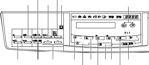
Indicators
GUIDE TO COMPONENTS AND THEIR FUNCTION |
Overall Information |
||||
1 |
2 |
3 |
4 |
||
|
|||||
5
1. Error indicators |
4. Counter |
These indicators are lit when a |
Displays the number of prints |
non-standard condition occurs |
entered. While printing, it shows |
within the machine. |
the number of prints remaining. |
2. Memory/Class Indicator |
5. Guidance Display |
Shows the number entered in |
Display the machine's condition. |
Memory or Class mode. |
|
3.Speed indicator
These indicators show the printing speed that is selected.
SM |
1-9 |
C231 |
Loading...