


DRILL STAND
Operation and Safety Notes
STOJAK DO WIERTARKI
Wskazówki dotyczące obsługi i bezpieczeństwa
FÚRÓÁLLVÁNY
Kezelési és biztonsági utalások
STOJALO ZA VRTALNI STROJ
Navodila za upravljanje in varnostna opozorila
STOJAN NA VRTAČKU
Pokyny pro obsluhu a bezpečnostní pokyny
STOJAN NA VŔTAČKU
Pokyny pre obsluhu a bezpečnostné pokyny
BOHRMASCHINENSTÄNDER
Bedienungsund Sicherheitshinweise
4 
Z31280

|
|
|
|
|
|
|
|
|
|
|
|
|
|
|
|
|
|
|
|
|
|
|
|
|
|
|
|
|
|
|
|
|
|
|
|
|
|
|
|
|
|
|
|
|
|
|
|
|
|
|
|
|
|
|
|
|
|
|
|
|
|
|
|
|
|
|
|
|
|
|
|
|
|
|
|
|
|
|
|
|
|
|
|
|
|
GB |
|
|
|
Operation and Safety Notes |
|
|
|
|
|
|
Page |
5 |
|
|
|||||||||||
|
|
PL |
|
|
|
Wskazówki dotyczące obsługi i bezpieczeństwa |
|
|
|
|
|
|
Strona |
7 |
|
|
|||||||||||
|
|
HU |
|
|
|
Kezelési és biztonsági utalások |
|
|
|
|
|
|
Oldal |
10 |
|
|
|||||||||||
|
|
SI |
|
|
|
Navodila za upravljanje in varnostna opozorila |
|
|
|
|
|
|
Stran |
13 |
|
|
|||||||||||
|
|
CZ |
|
|
|
Pokyny pro obsluhu a bezpečnostní pokyny |
|
|
|
|
|
|
Strana |
15 |
|
||||||||||||
|
|
SK |
|
|
|
Pokyny pre obsluhu a bezpečnostné pokyny |
|
|
|
|
|
|
Strana |
17 |
|
|
|||||||||||
|
|
DE / AT / CH |
|
|
|
Bedienungsund Sicherheitshinweise |
|
|
|
|
|
|
Seite |
20 |
|
|
|||||||||||
1 2
11
10
9
3
8
|
4 |
|
|
12 |
|
|
7
6
16 17
13
|
|
|
|
|
|
|
5 |
|
15 |
|
14 |
|
|
A |
B |
7
2
3

C |
13
|
|
|
|
|
|
|
|
|
|
|
|
|
|
14 |
|
|
4 |
|||
E |
17
G |
12 |
|
I |
10
8
D |
15 |
|
16
F |
3
H |
1 |
|
8 |
10
J |
4

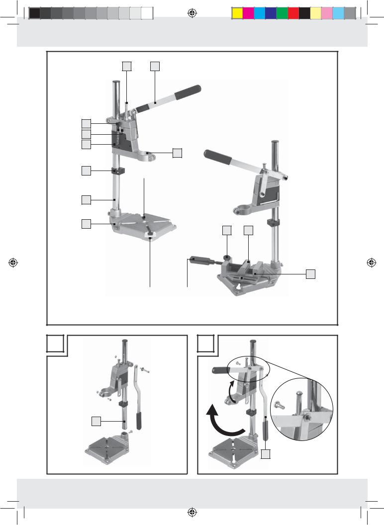
Drill stand
Intended use
The product is designed for commercial drills and is suitable for placing exactly defined holes at rightangles into wood, metal and ceramic tiles. It is possible to mount the work-piece securely during drilling. Consult the manufacturer‘s operating manual before using the drill. The product is not intended for commercial use.
|
Parts description |
|
Drill stand: |
||
1 |
Bolt |
|
2 |
Lever arm |
|
3 |
Drill holding fixture |
|
4 |
Guide slot (4 x) |
|
5 |
Drill hole (4 x) |
|
6 |
Base plate |
|
7 |
Pillar |
|
8 |
Block |
|
9 |
Slider |
|
10 |
Locking screw |
|
11 |
Drill depth gauge with indicator |
|
12 |
Screw |
|
Machine vice:
13Machine vice
14Long slot
15Locking device
16Quick-release button
17Clamping jaw
Contents
1Drill stand
1Hexagon key
1Machine vice
1Operating instructions
Technical Data
Drill holding fixture for |
|
clamping collar diameter: |
43 mm |
Drilling depth: |
to 60 mm steplessly |
|
adjustable |
Dimensions: |
155 x 505 x 225 mm |
|
(W x H x D) |
Clamping jaw width: |
65 mm |
Clamp width: |
65 mm |
Safety notes
YOU SHOULD STORE ALL SAFETY INFORMATION AND INSTRUCTIONS IN A SAFE PLACE IN CASE YOU NEED TO REFER TO THEM AGAIN IN THE FUTURE!
 CAUTION! RISK OF INJURY! When working with hand-operated electrical tool, slipping or loosening of the mounted work-piece can cause severe injuries. Therefore, never work on a mounted work-piece using a hand-operated electrical tool.
 CAUTION! RISK OF SHEARING OR CRUSHING INJURY! There is the risk of shearing or crushing injuries while working with the drill stand.
 CAUTION! RISK OF INJURY! Pay attention to flying chippings and splinters. There is the risk of injury.
Keep out of the reach of children. Store the product out of the reach of children.
Check the product for damage before each use. Please do not use this device if you find that it is damaged in any way.
Check that the screws are tight before each use.
Use the product on a solid, level and intact surface (e.g. a workbench).
Always disconnect the drill from the power supply before making adjustments or work breaks.
Wear protective gloves and safety goggles. The drill stand must be mounted on a workbench or a stable, tilt-free table, to ensure a safe work. Use the drill holes 5 in the base plate 6 .
GB 5
|
|
|
|
|
|
|
|
|
|
|
|
|
|
|
|
|
|
|
|
|
|
|
|
|
|
|
|
|
|
|
|
|
|
|
|
|
|
|
|
|
|
|
|
|
|
|
|
|
|
|
|
|
|
|
|
|
|
|
|
|
|
|
|
|
|
|
|
|
|
|
|
|
|
|
|
|
|
|
|
|
|
|
|
|
|
|
|
|
|
|
|
|
|
|
|
|
|
|
|
|
|
|
|
|
|
|
|
|
|
|
|
|
|
|
|
|
|
|
|
|
|
|
|
|
|
|
|
|
|
|
|
|
|
|
|
|
|
|
|
|
|
|
|
|
|
|
|
|
|
|
|
|
|
|
|
|
|
|
|
|
|
|
|
|
|
|
|
|
|
|
|
|
|
|
|
|
|
|
|
|
|
|
|
|
|
|
|
|
|
|
|
|
|
|
|
|
|
|
|
|
|
|
Assembly |
|
|
|
|
|
|
|
|
|
Adjusting the drill depth |
|
|
|
|
||||||||||||||||
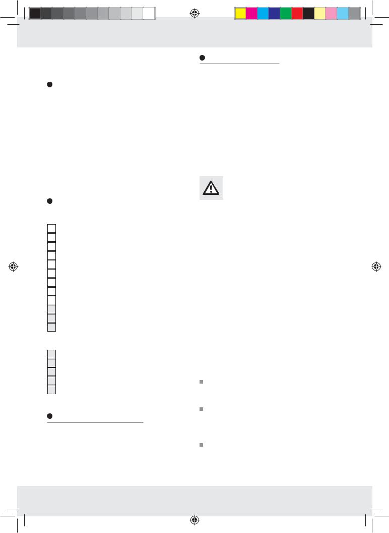
Note: You need a 5mm hexagon key (provided), two open-ended spanners (10 mm & 14 mm) and a slot screwdriver (1.2 x 8.0 mm) for assembly and adjustment.
Connect the pillar 7 to the base plate 6 . Then fix the slider 9 on the pillar (see Fig. A). Mount the lever arm 2 onto the slider (see Fig. B). Tighten the screws and nuts as tight as possible. Mount the machine vice 13 onto the base plate. To do this connect the screws with the guide slots 4 in the base plate through the two long slots 14 (see Fig. C).
Note: The machine vice can be positioned exactly by moving the guide slots and long slots.
Mounting the work-piece
Hold the quick-release button 16 pressed and pull the locking device 15 back as far as it goes (see Fig. D).
Place the work-piece into the machine vice 13 . Press the quick-release button and push the locking device with the clamping jaw 17 against the work-piece.
Fix the work-piece with a right turn (see Fig. E).
Clamping in and adjusting the drill
Fit the drill with its clamping collar into the drill holding fixture 3 and tighten securely (see Fig. F). Insert a suitable drill bit into the chuck. Unscrew bolt 12 (see Fig. G).
Move the slider 9 with the clamped in drill on the pillar 7 , until the drill nearly touches the work-piece.
Retighten screw securely.
Loosen the block 8 and slide it up to the slider 9 (see Fig. H).
Loosen the locking screw 10 by turning it to the left (see Fig. H).
Make sure that the bolt 1 will be released doing this and slides down to the lowest position. Move the lever arm 2 down and read o the desired drill depth on the drill gauge with indicator 11 .
Fix the locking screw 10 and block 8 with a right turn (see Fig. I).
Adjusting the work piece
Loosen the fixing screws of the machine vice 13 . Adjust the machine vice with the work piece by sliding it into position.
Mark the exact position and punch a drilling point on the work-piece. Retighten the machine vice (see Fig. J).
Storage and care
Store the hexagon key in the fixture on the slider. Store the product in a dry place, out of the reach of children.
Clean the product with a damp cloth.
Lightly grease the moving parts, rub the plain metal parts with an oily cloth to protect them from rust.
Disposal
The packaging is made from environmentally friendly materials, which may be disposed through your local recycling facilities.
Contact your local refuse disposal authority for more details of how to dispose of your worn-out product.
6GB
Stojak do wiertarki
Zastosowanie zgodne z przeznaczenie
Produkt dostosowany jest do standardowych wiertarek w celu dokładnego ustawienia odwiertów pod kątem prostym w drewnie metalu i płytek ceramicznych. Podczas wiercenia możliwe jest bezpieczne zamocowanie materiału przeznaczonego do obróbki. Przed użyciem wiertarki należy konieczne zapoznać się z instrukcją obsługi. Produkt nie jest przeznaczony do użytku komercyjnego.
|
Opis części |
|
Stojak na wiertarkę: |
||
1 |
Trzpień |
|
2 |
Ramię dźwigni |
|
3 |
Uchwyt na wiertarkę |
|
4 |
Wpust wprowadzący (4 x) |
|
5 |
Otwór wiertniczy (4 x) |
|
6 |
Płyta fundamentowa |
|
7 |
Słupek |
|
8 |
Opór nastawny |
|
9 |
Głowica dźwigniowa |
|
10Śruba mocująca
11Pomiar głębokości wiertła ze wskaźnikiem
12Śruba
Imadło maszynowe śrubowe:
13Imadło maszynowe śrubowe
14Otwór podłużny
15Ustalacz
16Głowica szybkomocująca
17Szczęka mocująca
Zawartość dostawy
1Stojak na wiertarkę
1Klucz imbusowy
1Imadło maszynowe śrubowe
1Instrukcja obsługi
Dane techniczne
Uchwyt na wiertarkę |
|
do urządzeń o średnicy: |
43 mm |
Głębokość: |
do 60 mm możliwa |
|
regulacja bezstop- |
|
niowa |
Wymiary: |
155 x 505 x 225 mm |
|
(szer. x wys. x gł.) |
Szerokość szczęki |
|
mocującej: |
65 mm |
Rozpiętość: |
65 mm |
Wskazówki dotyczące bezpieczeństwa
PRZECHOWUJ WSZYSTKIE WSKAZÓWKI DOTYCZĄCE BEZPIECZEŃSTWA I INSTRUKCJE NA PRZYSZŁOŚĆ!
 UWAGA! NIEBEZPIECZEŃSTWO POWSTANIA OBRAŻEŃ! W przypadku wypadnięcia lub poluzowania się umocowanych przedmiotów przeznaczonych do obróbki podczas pracy z ręcznymi narzędziami elektrycznymi może dojścić do ciężkich obrażeń. Dlatego nigdy nie należy obrabiać umocowanych przedmiotów przeznaczonych do obróbki urządzeniami elektrycznymi.
 OSTROŻNIE! NIEBEZPIECZEŃSTWO ZMIAŻDŻENIA! Podczas pracy ze stojakiem na wiertarkę istnieje możliwość zmiażdżenia.
 OSTROŻNIE! RYZYKO OBRAŻEŃ!
Należy zwrócić uwagę na latające wióry i drzazgi. Niebezpieczeństwo zranienia.
Produkt należy trzymać z dala od dzieci. Produkt należy przechowywać poza zasięgiem dzieci.
Przed użyciem należy skontrolować produkt pod względem uszkodzeń. Urządzenia nie należy używać w przypadku stwierdzenia uszkodzeń.
Przed każdym użyciem należy skontrolować dokładne umocowanie wszystkich śrub w urządzeniu.
PL 7
 Loading...