


PDM 250 A1


English ......................................................................................................... 2
Polski ........................................................................................................ 19
Magyar ..................................................................................................... 36
Slovenščina ............................................................................................... 53
Česky ........................................................................................................ 71
Slovenčina ................................................................................................ 88
V 1.2

POWERFIX PDM 250 A1
Content
Introduction ...................................................................................................... 3
Intended use ..................................................................................................... 3
Supplied items .................................................................................................. 4
Technical data................................................................................................... 5
Safety instructions ............................................................................................ 7
Copyright ......................................................................................................... 9
Prior to use ....................................................................................................... 9
Inserting/changing the battery ....................................................................................................... 10
First use .......................................................................................................... 11
Overflow indicator .......................................................................................................................... 11
DC voltage measurement ............................................................................................................... 11
AC voltage measurement ............................................................................................................... 11
AC current measurement ................................................................................................................ 12
DC current measurement ................................................................................................................ 12
Battery test ....................................................................................................................................... 12
Resistance measurement ................................................................................................................. 13
Continuity test .................................................................................................................................. 13
Diode test ......................................................................................................................................... 14
HOLD function ................................................................................................................................. 14
One-hand operation ....................................................................................................................... 15
Setting up/hanging up the multimeter ........................................................................................... 15
Cleaning / maintenance .................................................................................. 15
Maintenance ................................................................................................................................... 15
Replacing the fuse ........................................................................................................................... 16
Cleaning........................................................................................................................................... 17
Environmental and disposal information ........................................................ 17
Conformity information .................................................................................. 17
Warranty and servicing advice ....................................................................... 18
2 - English

POWERFIX PDM 250 A1
Introduction
Thank you for purchasing a POWERFIX product.
The POWERFIX Digital Multimeter PDM 250 A1, referred to below as multimeter, is used to
measure AC/DC voltages and AC/DC currents. The multimeter also has a battery test, a
resistance measurement, a diode test and a continuity test.
Intended use
This multimeter is not designed for commercial use or installation and operation in a company.
This multimeter may only be used for private purposes, and any other use is not as intended. This
multimeter meets all relevant norms and standards in conjunction with CE conformity. In the event
of any modification to the multimeter that was not approved by the manufacturer, compliance with
these standards is no longer guaranteed. The manufacturer does not accept any liability for any
resulting damage or faults in such cases.
Please observe the regulations and laws in the country of use.
English - 3

POWERFIX PDM 250 A1
Supplied items
Multimeter
2 test probes (including test lead)
Holster
9V battery
These instructions
These instructions have a fold-out cover. The multimeter is illustrated with a numbering system on
the inside of the cover. The numbers indicate the following:
1 Screen
2 Holster
3 HOLD button (Save button)
4 Range selector switch
5 COM jack (earth)
6 V/Ω jack
7 Test probes (including test lead)
8 10A jack
9 mA/BATT jack
10 On/off button
4 - English
POWERFIX PDM 250 A1
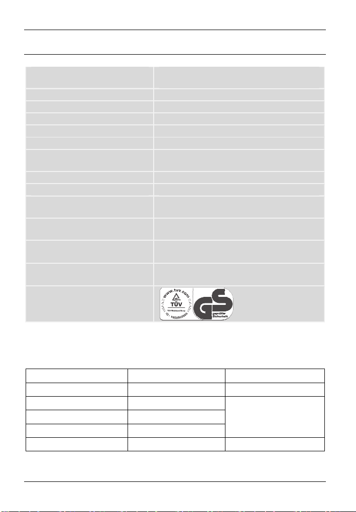
Technical data
Screen 3.5 digit LCD display, max. display: 1999
Measuring rate approximately 3 measurements per second
Test lead length each approximately 80 cm
Battery type Standard 9V battery
Overvoltage category CAT II 250 V
Hold function yes
Automatic polarity indicator yes
"Low Bat" indicator yes
Auto power OFF function yes
Operating temperature, air humidity 0°C to +40°C; max. 75 % rel. humidity
Storage temperature, air humidity -10°C to +50°C; max. 85 % rel. humidity
Dimensions (W x H x D) 85 x 164 x 35 mm (without holster)
93 x 178 x 52 mm (with holster)
Weight 204g (without holster, without battery)
345g (with holster, without battery)
Tested safety:
The technical data and design may be changed without notification.
DC voltage
Range Resolution Precision
200mV 0.1mV ± (0.5%+5)
2V 1mV
20V 10mV
200V 0.1V
250V 1V ± (1.0%+5)
Input impedance: 10MΩ
Overload protection: 250V DC/AC RMS
± (0.8%+5)
English - 5

POWERFIX PDM 250 A1
AC voltage
Range Resolution Precision
2V 1mV
20V 10mV
200V 0.1V
250V 1V ± (1.2%+5)
Input impedance: 10MΩ
Frequency range: 40Hz to 400Hz
Overload protection: 250V AC RMS
Display: average value (RMS of the sine wave)
DC current
Range Resolution Precision
200μA 0.1μA
2mA 1μA
20mA 10μA
200mA 0.1mA
10A 10mA ± (2.0%+5)
Overload protection: F 250mA / 250V fuse (10A range unfused)
Maximum input current: 10A (input current > 2A for continuous measurement < 15 seconds and
interval > 15 minutes)
AC current
Range Resolution Precision
2mA 1μA ± (1.2%+5)
20mA 10μA
200mA 0.1mA
10A 10mA ± (3.0%+7)
Overload protection: F 250mA / 250V fuse (10A range unfused)
Maximum input current: 10A (input current > 2A for continuous measurement < 15 seconds and
interval > 15 minutes)
Frequency range: 40Hz to 400Hz
Display: average value (RMS of the sine wave)
± (1.0%+5)
± (1.0%+5)
± (1.2%+5)
± (1.5%+5)
6 - English
POWERFIX PDM 250 A1
Resistance
Range Resolution Precision
200Ω 0.1Ω ± (1.0%+5)
2kΩ 1Ω
20kΩ 10Ω
200kΩ 0.1kΩ
2MΩ 1kΩ
20MΩ 10kΩ ± (1.2%+3)
Overload protection: 250V
Battery test
Range Consumption
1.5V ±20mA
9V ±5mA
The specified precision in ± (% of the display + number of digits) is guaranteed for a period of
one year at an ambient temperature from 18°C to 28°C and maximum air humidity of 75%.
± (0.8%+3)
Safety instructions
Before using this multimeter for the first time, always read the following instructions and pay
attention to all warnings, even if you are familiar with handling electronic devices. Store these
instructions in a safe place for future reference. If you sell the multimeter or pass it on, always
include these instructions.
This symbol indicates important information for safe operation of the
multimeter and the safety of the user.
This symbol indicates other important information on the topic.
English - 7
POWERFIX PDM 250 A1
Electrical devices do not belong in the hands of children. Persons with disabilities should
also only use electrical devices within the scope of their abilities. Never allow children or
persons with disabilities to use electrical devices unsupervised. They may not recognise
potential risks. Batteries and small parts may cause choking resulting in death or serious
injury. Store the battery in a safe place. If a battery is swallowed, seek medical help
immediately. Also always keep plastic packaging out of reach as it poses a suffocation risk!
If smoke is produced, or there are any unusual sounds or smells, stop measuring
immediately. In these cases, the multimeter should not be used until it has been inspected by
authorised service personnel. Never inhale smoke from a potential device fire. If you have
inhaled smoke, however, consult a doctor. The inhalation of smoke can be harmful.
The test probes may be handled only behind the finger protection as otherwise there is a risk
of an electric shock when measuring!
If the multimeter or the test probes are damaged (including test lead), they must not be used.
It poses an electric shock risk!
Pay particular attention to your safety when dealing with AC voltages over 30V or DC
voltages over 60V. It poses an electric shock risk!
Never operate the multimeter when the housing is open. It poses an electric shock risk!
Ensure that you do not touch the test probes and the jacks to be measured during a
measurement in order to avoid an electric shock.
Do not use the multimeter in wet or damp environments. Also ensure that your hands and
shoes are dry as there is a risk of an electric shock otherwise!
Do not use the multimeter in the vicinity of explosive gases or vapours or in a dusty
environment. It poses a risk of explosion!
Ensure that no fire sources (e.g. burning candles) are placed on or near the multimeter. It
poses a fire hazard!
Do not exceed the maximum specified input values for the individual measuring ranges.
Otherwise, the multimeter could be damaged.
The multimeter must be disconnected from the test object before changing the measuring
range as the multimeter could be damaged otherwise.
8 - English

POWERFIX PDM 250 A1
When working with the test probes, first connect the black test lead to the COM jack before
you connect the red test lead. When disconnecting the test probes, first remove the red test
probe.
Never connect a voltage source to the test probes if the areas continuity test, resistance
measurement, diode test and current measurement are selected. Otherwise, the multimeter
could be damaged.
The multimeter may not be exposed to any direct heat sources (e.g. heating) or any direct
sunlight or artificial light. Also avoid contact with dripping water and splashes and corrosive
liquids. Never operate the multimeter near water. In particular, the multimeter should never
be submerged in liquid (do not place any items filled with liquid, e.g. vases or drinks on the
multimeter). Also ensure that the multimeter is not exposed to any excessive shocks or
vibrations. Furthermore, no foreign objects may penetrate the multimeter. Otherwise, the
multimeter could be damaged.
Copyright
All information contained in these instructions is subject to copyright and is provided for
information purposes only. It is only permitted to copy or duplicate data and information with the
express and written consent of the author. This also includes commercial use of the content and
data. The text and illustrations are based on the state of the art at the time of printing.
Prior to use
Remove the multimeter and the accessories from the packaging.
Check the multimeter and the accessories for signs of damage. If damaged, the multimeter may
not be used.
English - 9
POWERFIX PDM 250 A1
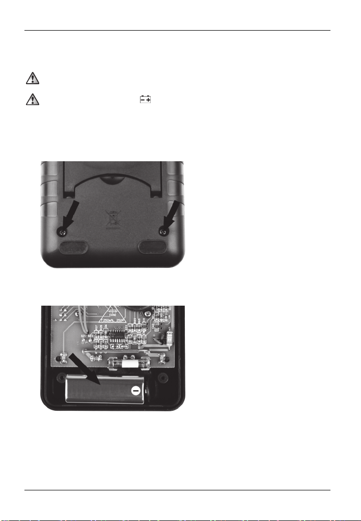
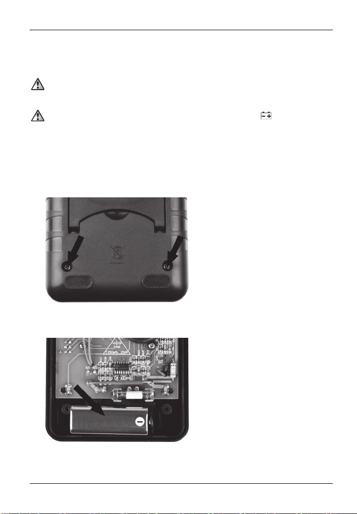
Inserting/changing the battery
The multimeter is powered by a 9V battery. To insert or replace the battery, proceed as follows:
Switch off the multimeter and remove all test leads before opening the multimeter!
If the battery is exhausted, the
replaced as soon as possible to ensure that the multimeter continues to work properly.
Remove the holster [2].
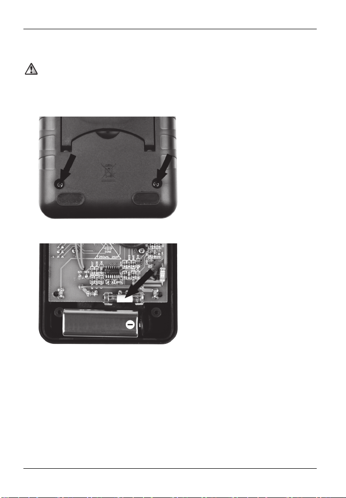
Remove the two screws on the back of the multimeter and remove the back panel.
Connect the 9V battery with the correct polarity (note + and –) to the battery clip and place
the 9V battery in the battery compartment.
icon appears on the display [1]. The battery should be
Replace the back panel and screw it tight with the two screws.
Re-insert the multimeter in the holster [2].
10 - English

POWERFIX PDM 250 A1
First use
Never exceed the maximum permissible input values.
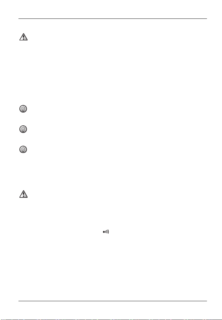
Before measuring, remove the cover of the test probes [7] and the test lead and switch on the
multimeter by pressing the on/off button [10]. The multimeter has an auto power OFF function
and switches itself off automatically after longer periods of non-use. However, you can also switch
off the multimeter directly with the on/off button [10].
You obtain a more accurate measurement result if you use the smallest possible measuring
range.
Overflow indicator
The multimeter has an overflow indicator. If a measured value exceeds the range limit of the
selected measuring range, "1" is indicated on the display [1]. In this case, switch to a higher
measuring range immediately if possible, or remove the test probes [7] from the test object.
DC voltage measurement
Connect the black test lead to the COM jack [5] and the red test lead to the V/Ω jack [6].
Set the range selector switch [4] to the desired range in the DC voltage measuring range
.
V
If you do not know the voltage, first set the highest possible measuring range and then
reduce it gradually to the lower ranges until you obtain a satisfactory measurement result.
Connect the test probes [7] to the test object.
The measurement result is then indicated on the display [1]. A negative sign is indicated in
front of the measured value for a negative measurement result.
AC voltage measurement
Connect the black test lead to the COM jack [5] and the red test lead to the V/Ω jack [6].
Set the range selector switch [4] to the desired range in the AC voltage measuring range V
If you do not know the voltage, first set the highest possible measuring range and then
reduce it gradually to the lower ranges until you obtain a satisfactory measurement result.
Connect the test probes [7] to the test object.
The measurement result is then indicated on the display [1].
English - 11
.
~

POWERFIX PDM 250 A1
AC current measurement
Connect the black test lead to the COM jack [5] and the red test lead to the 10A jack [8]
(for currents > 200mA) or to the mA/BATT jack [9] (for currents < 200mA).
Set the range selector switch [4] to the desired range in the AC current measuring range A
If you do not know the current, first set the highest possible measuring range and then reduce
it gradually to the lower ranges until you obtain a satisfactory measurement result.
Connect the test probes [7] in series to the test object.
The measurement result is then indicated on the display [1].
DC current measurement
Connect the black test lead to the COM jack [5] and the red test lead to the 10A jack [8]
(for currents > 200mA) or to the mA/BATT jack [9] (for currents < 200mA).
Set the range selector switch [4] to the desired range in the DC current measuring range
.
A
If you do not know the current, first set the highest possible measuring range and then reduce
it gradually to the lower ranges until you obtain a satisfactory measurement result.
Connect the test probes [7] in series to the test object.
The measurement result is then indicated on the display [1]. A negative sign is indicated in
front of the measured value for a negative measurement result.
Battery test
Connect the black test lead to the COM jack [5] and the red test lead to the mA/BATT jack
[9].
Set the range selector switch [4] to the corresponding battery voltage range 1.5V or 9V in
the BATT range.
.
~
Connect the red test probe [7] to the positive pole and the black test probe [7] to the
negative pole of the battery.
The measurement result is then indicated on the display [1].
In the measuring ranges BATT 1.5V and BATT 9V, the battery to be measured is charged by
an internal resistance, thus you obtain practical information on the condition and
functionality of the tested battery.
12 - English
POWERFIX PDM 250 A1
Resistance measurement
Ensure that all circuit elements, circuits and components to be measured and other test
objects are completely switched off and discharged. Otherwise, the multimeter could be
damaged.
Connect the black test lead to the COM jack [5] and the red test lead to the V/Ω jack [6].
Set the range selector switch [4] to the desired range in the Ω measuring range.
Connect the test probes [7] to the test object.
The measurement result is then indicated on the display [1].
For resistances > 1MΩ, the measurement may take a few seconds. In this case, wait until the
measured value has stabilised.
The test probes [7] should be handled only behind the finger protection to avoid a distorted
measurement result.
For measurements of low resistances (200Ω range), the internal resistance of the test leads
can lead to a distorted result. To avoid such an error, note the value of the measurement for
short-circuited test probes and deduct this from the value of the actual measurement.
Continuity test
Ensure that all circuit elements, circuits and components to be measured and other test
objects are completely switched off and discharged. Otherwise, the multimeter could be
damaged.
Connect the black test lead to the COM jack [5] and the red test lead to the V/Ω jack [6].
Set the range selector switch [4] to the
Connect the test probes [7] to the test object.
If the resistance is less than approximately
result is indica
ted on the display [1].
position in the Ω measuring range.
60
Ω, the buzzer sounds and the measurement
English - 13

POWERFIX PDM 250 A1
Diode test
Ensure that all circuit elements, circuits and components to be measured and other test
objects are completely switched off and discharged. Otherwise, the multimeter could be
damaged.
Connect the black test lead to the COM jack [5] and the red test lead to the V/Ω jack [6].
Set the range selector switch [4] to the
Connect the red test probe [7] to the anode and the black test probe [7] to the cathode of
the diode to be tested.
The forward voltage is indicated in volts on the display [1]. If "1" is displayed on the display
[1], the diode is measured in the reverse biased-direction or the diode is defective. Perform
an opposite pole measurement for check purposes.
position in the Ω measuring range.
HOLD function
A measured value on the display [1] can be saved by pressing the HOLD button [3]. Press the
HOLD button [3] again to return to the measuring mode.
14 - English
One-hand operation
You can also use the multimeter with one
hand. To do so, insert a test probe [7] in one
of the slots on the back of the holster [2]. You
can then perform your measurements as usual
without having to put down the multimeter.
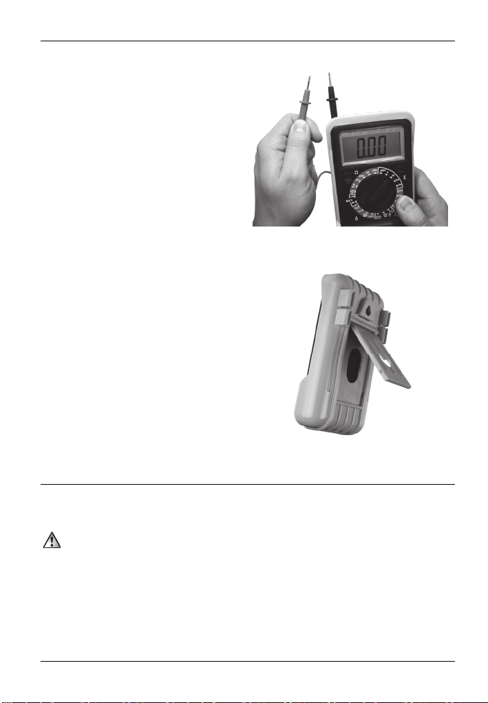
Setting up/hanging up the multimeter
You can set up or hang up the multimeter
using the holster [2]. Open out the stand at the
back of the holster [2] to set up the multimeter.
There is also a slot above the stand to
facilitate hanging up the multimeter.
POWERFIX PDM 250 A1
Cleaning / maintenance
Maintenance
Maintenance work is necessary if the multimeter has been damaged or if liquid or objects
have penetrated inside the housing, the multimeter has been exposed to rain or moisture or
if it does not work correctly or has been dropped. In these cases, the multimeter should not
be used until it has been inspected by authorised service personnel. Only have qualified
personnel carry out the maintenance work on the device.
English - 15
POWERFIX PDM 250 A1
Replacing the fuse
To replace the fuse, proceed as follows:
Switch off the multimeter and remove all test leads before opening the multimeter!
Remove the holster [2].
Remove the two screws on the back of the multimeter and remove the back panel.
Replace the fuse with another of the same type.
Replace the back panel and screw it tight with the two screws.
Re-insert the multimeter in the holster [2].
16 - English
POWERFIX PDM 250 A1
Cleaning
Switch off the multimeter and remove all test leads before cleaning the multimeter!
Use a dry cloth for cleaning and never use any solvent or cleaner that would corrode the plastic
materials. Ensure that no liquid enters the housing. Use a slightly damp cloth for more stubborn
dirt.
Environmental and disposal information
When this symbol appears on a product, this indicates that the product is
subject to the European Directive 2002/96/EC. All old electrical and
electronic devices must be separated from normal household waste and
disposed of at designated state facilities. The correct disposal of old devices in
this manner will prevent environmental pollution and human health hazards.
For further information about proper disposal, contact your local authorities,
waste disposal office or the shop where you bought the device.
Remember to protect the environment. Used batteries should not be disposed of in domestic
waste. They must be taken to a collection point for old batteries. Please note that only discharged
batteries may be deposited in collection bins for portable batteries. Care must be taken to ensure
that batteries that are not fully discharged do not short circuit.
Dispose of the packaging in an environmentally compatible manner. Cardboard can be put out
for municipal paper collections or brought to public collection points for recycling. Films and
plastic used for packaging the device are collected by your local disposal services and disposed
of in an environmentally compatible manner.
Conformity information
This device meets the basic requirements and other relevant regulations of the
EMC Directive 2004/108/EC, the Low Voltage Directive 2006/95/EC as
well as the RoHS Directive 2011/65/EU. The Declaration of Conformity can
be found at the end of these instructions.
English - 17
POWERFIX PDM 250 A1
Warranty and servicing advice
Warranty of TARGA GmbH
This device is sold with three years warranty from the date of purchase. Please keep the original
receipt in a safe place as proof of purchase. Before using your product for the first time, please
read the enclosed documentation or online help. Should any problems arise which cannot be
solved in this way, please call our hotline. Please have the article number and, if available, the
serial number to hand for all enquiries. If it is not possible to solve the problem on the phone, our
hotline support staff will initiate further servicing procedures depending on the fault. Within the
warranty period the product will be repaired or replaced free of charge as we deem appropriate.
No new warranty period commences if the product is repaired or replaced. Consumables such as
batteries, rechargeable batteries and lamps are not covered by the warranty.
Your statutory rights towards the seller are not affected or restricted by this warranty.
Service
E-Mail: service.GB@targa-online.com
E-Mail: service.IE@targa-online.com
E-Mail: service.MT@targa-online.com
E-Mail: service.CY@targa-online.com
TARGA GmbH
IAN: 89117
Manufacturer
Coesterweg 45
59494 SOEST
GERMANY
Phone: 0207 – 36 50 744
Phone: 01 – 242 15 83
Phone: 800 – 62 175
Phone: 800 – 92 496
18 - English

POWERFIX PDM 250 A1
Spis treści
Wstęp ............................................................................................................. 20
Użytkowanie zgodne z przeznaczeniem ......................................................... 20
Zakres dostawy .............................................................................................. 21
Dane techniczne .............................................................................................. 22
Przepisy bezpieczeństwa ................................................................................ 24
Prawo autorskie ............................................................................................. 26
Przed pierwszym uruchomieniem ................................................................... 26
Wkładanie / wymiana baterii ....................................................................................................... 27
Uruchomienie .................................................................................................. 28
Wskaźnik przepełnienia ................................................................................................................. 28
Pomiar napięcia stałego DC .......................................................................................................... 28
Pomiar napięcia przemiennego AC .............................................................................................. 28
Pomiar prądu przemiennego AC ................................................................................................... 29
Pomiar prądu stałego DC ............................................................................................................... 29
Test baterii........................................................................................................................................ 30
Pomiar rezystancji ........................................................................................................................... 30
Sprawdzenie ciągłości obwodu .................................................................................................... 31
Test diod .......................................................................................................................................... 31
Funkcja Hold ................................................................................................................................... 31
Obsługa jednoręczna ..................................................................................................................... 32
Ustawianie / zawieszanie miernika uniwersalnego .................................................................... 32
Konserwacja / czyszczenie ............................................................................. 32
Konserwacja .................................................................................................................................... 32
Wymiana bezpiecznika ................................................................................................................. 33
Czyszczenie .................................................................................................................................... 34
Wskazówki dotyczące ochrony środowiska i prawidłowego usuwania ........ 34
Deklaracja zgodności ...................................................................................... 34
Informacje na temat gwarancji i serwisowania .............................................. 35
Polski – 19

POWERFIX PDM 250 A1
Wstęp
Dziękujemy za zakup produktu POWERFIX.
Cyfrowy miernik uniwersalny POWERFIX PDM 250 A1, zwany dalej "miernik uniwersalny",
umożliwia pomiar napięć stałych i przemiennych oraz prądów stałych i przemiennych. Ponadto,
miernik uniwersalny jest wyposażony w test baterii, pomiar rezystancji, test diod i test ciągłości
obwodu.
Użytkowanie zgodne z przeznaczeniem
Ten miernik uniwersalny nie jest przewidziany do stosowania w przedsiębiorstwach ani w
zastosowaniach komercyjnych. Miernik uniwersalny jest przeznaczony wyłącznie do użytku
prywatnego, a każde inne użytkowanie uznaje się za niezgodne z przeznaczeniem. Ten miernik
uniwersalny spełnia wymagania wszystkich odnośnych norm i dyrektyw, związanych ze
zgodnością CE. W przypadku nieuzgodnionych z producentem modyfikacji miernika
uniwersalnego nie można zagwarantować spełnienia wymagań tych norm. Producent nie ponosi
żadnej odpowiedzialności za wynikłe z tego szkody lub zakłócenia.
Należy przestrzegać przepisów krajowych lub przepisów kraju użytkowania.
20 - Polski

POWERFIX PDM 250 A1
Zakres dostawy
Miernik uniwersalny
2 końcówki pomiarowe (łącznie z przewodami pomiarowymi)
Kabura
Bateria blokowa 9V
Niniejsza instrukcja
Niniejsza instrukcja ma odchylaną okładkę. Na wewnętrznej stronie odchylanej okładki jest
przedstawiony miernik uniwersalny wraz z oznaczeniami liczbowymi. Liczby mają następujące
znaczenie:
1 Wyświetlacz
2 Kabura
3 Przycisk HOLD (przycisk pamięci)
4 Przełącznik zakresów
5 Przyłącze COM (masa)
6 Przyłącze V/Ω
7 Końcówki pomiarowe (łącznie z przewodami pomiarowymi)
8 Przyłącze 10A
9 Przyłącze mA/BATT
10 Włącznik/wyłącznik
Polski – 21
POWERFIX PDM 250 A1
Dane techniczne
Wyświetlacz
Częstotliwość pomiaru ok. 3 pomiary/sekundę
Długość przewodów pomiarowych po ok. 80 cm
Typ baterii Bateria blokowa 9V
Kategoria przepięciowa CAT II 250 V
Funkcja Hold tak
Automatyczne wskazanie
biegunowości
Wskazanie niskiego poziomu baterii tak
Funkcja automatycznego wyłączenia tak
Temperatura robocza, wilgotność
powietrza
Temperatura składowania, wilgotność
powietrza
Wymiary (szer. x wys. x głęb.) 85 x 164 x 35 mm (bez kabury)
Masa 204 g (bez kabury, bez baterii)
Sprawdzone bezpieczeństwo:
Zastrzegamy możliwość zmian danych technicznych i konstrukcyjnych bez wcześniejszego
uprzedzenia.
Napięcie stałe
Zakres Rozdzielczość Dokładność
200mV 0,1mV ± (0,5%+5)
2V 1mV
20V 10mV
200V 0,1V
250V 1V ± (1,0%+5)
Impedancja wejściowa: 10MΩ
Ochrona przed przeciążeniem: 250V DC/AC RMS
3 ½-pozycyjny wyświetlacz LCD, maks. wskazanie:
1999
tak
0°C do +40 °C, maks. 75 % wilgotności
względnej
-10 °C do +50 °C, maks. 85 % wilgotności
względnej
93 x 178 x 52 mm (z kaburą)
345 g (z kaburą, bez baterii)
± (0,8%+5)
22 - Polski

POWERFIX PDM 250 A1
Napięcie przemienne
Zakres Rozdzielczość Dokładność
2V 1mV
20V 10mV
200V 0,1V
250V 1V ± (1,2%+5)
Impedancja wejściowa: 10MΩ
Zakres częstotliwości: 40Hz do 400Hz
Ochrona przed przeciążeniem: 250V AC RMS
Wskazania: Wartość średnia (RMS fali sinusoidalnej)
Prąd stały
Zakres Rozdzielczość Dokładność
200μA 0,1μA
2mA 1μA
20mA 10μA
200mA 0,1mA
10A 10mA ± (2,0%+5)
Ochrona przed przeciążeniem: Bezpiecznik F 250mA / 250V (zakres 10A niezabezpieczony)
Maksymalny prąd wejściowy: 10A (prąd wejściowy > 2A przy pomiarze ciągłym < 15 s i
interwale > 15 min)
Prąd przemienny
Zakres Rozdzielczość Dokładność
2mA 1μA ± (1,2%+5)
20mA 10μA
200mA 0,1mA
10A 10mA ± (3,0%+7)
Ochrona przed przeciążeniem: Bezpiecznik F 250mA / 250V (zakres 10A niezabezpieczony)
Maksymalny prąd wejściowy: 10A (prąd wejściowy > 2A przy pomiarze ciągłym < 15 s i
interwale > 15 min)
Zakres częstotliwości: 40Hz do 400Hz
Wskazania: Wartość średnia (RMS fali sinusoidalnej)
± (1,0%+5)
± (1,0%+5)
± (1,2%+5)
± (1,5%+5)
Polski – 23
POWERFIX PDM 250 A1
Rezystancja
Zakres Rozdzielczość Dokładność
200Ω 0,1Ω ± (1,0%+5)
2kΩ 1Ω
20kΩ 10Ω
200kΩ 0,1kΩ
2MΩ 1kΩ
20MΩ 10kΩ ± (1,2%+3)
Ochrona przed przeciążeniem: 250V
Test baterii
Zakres Zużycie
1,5V ±20mA
9V ±5mA
Podana dokładność w ± (% wskazania + liczba pozycji) jest gwarantowana przez okres jednego
roku przy temperaturze otoczenia 18°C do 28°C i maksymalnej wilgotności powietrza 75%.
± (0,8%+3)
Przepisy bezpieczeństwa
Przed pierwszym użyciem miernika uniwersalnego prosimy dokładnie zapoznać się z poniższymi
instrukcjami. Należy stosować się do wszystkich ostrzeżeń o zagrożeniach, nawet jeśli masz
doświadczenie w obsłudze urządzeń elektronicznych. Niniejszą instrukcję należy starannie
przechowywać do wykorzystania w przyszłości. W razie sprzedaży lub przekazania miernika
uniwersalnego należy koniecznie dołączyć do niego niniejszą instrukcję.
Symbol ten oznacza ważne instrukcje do bezpiecznej eksploatacji miernika
uniwersalnego i do ochrony użytkownika.
Ten symbol oznacza dalsze, przydatne informacje na ten temat.
24 - Polski
POWERFIX PDM 250 A1
Urządzenia elektryczne trzymać poza zasięgiem dzieci. Także osoby z upośledzeniami
powinny używać urządzeń elektrycznych tylko w granicach swoich możliwości. Nigdy nie
należy pozwalać dzieciom ani osobom z upośledzeniami używać urządzeń elektrycznych
bez nadzoru. Te grupy osób nie zawsze mogą prawidłowo rozpoznać ewentualne
zagrożenia. Baterie i drobne części mogą w razie połknięcia stanowić zagrożenie dla
życia. Baterię należy przechowywać poza zasięgiem dzieci. W razie połknięcia baterii
należy natychmiast wezwać lekarza. Folie z opakowań należy także przechowywać poza
zasięgiem dzieci. Istnieje niebezpieczeństwo uduszenia!
W razie stwierdzenia tworzenia się dymu, zauważenia dziwnych odgłosów lub zapachów
natychmiast przerwać pomiar. W takich przypadkach miernika uniwersalnego nie wolno
dalej używać, dopóki nie zostanie on sprawdzony przez specjalistę. W żadnym przypadku
nie wolno wdychać dymu z możliwego pożaru urządzenia. O ile mimo to doszło do
wdychania dymu, należy udać się do lekarza. Wdychanie dymu może być szkodliwe dla
zdrowia.
Końcówki pomiarowe należy chwytać tylko za kołnierzem ochronnym, w przeciwnym razie
podczas pomiaru grozi porażenie prądem elektrycznym!
W razie uszkodzenia miernika uniwersalnego lub końcówek pomiarowych (łącznie z
przewodami pomiarowymi) nie wolno ich dalej używać. Niebezpieczeństwo porażenia
prądem elektrycznym!
Należy szczególnie uważać na swoje bezpieczeństwo przy pomiarach napięć
przemiennych powyżej 30V lub napięć stałych powyżej 60V. Niebezpieczeństwo
porażenia prądem elektrycznym!
Nigdy nie używać miernika uniwersalnego przy otwartej obudowie. Niebezpieczeństwo
porażenia prądem elektrycznym!
Należy uważać, by podczas pomiaru nie dotknąć końcówek pomiarowych ani punktów
pomiaru, by uniknąć porażenia prądem elektrycznym.
Nie należy używać miernika uniwersalnego w mokrym lub wilgotnym otoczeniu. Należy
poza tym uważać, by dłonie i buty były suche, w przeciwnym razie istnieje
niebezpieczeństwo porażenia prądem elektrycznym!
Nie używać miernika uniwersalnego w pobliżu wybuchowych gazów, par ani w obecności
pyłów. Istnieje niebezpieczeństwo eksplozji!
Dopilnować, by na mierniku uniwersalnym lub w jego pobliżu nie było żadnych źródeł
otwartego ognia (np. palące się świece). Istnieje niebezpieczeństwo pożaru!
Polski – 25
POWERFIX PDM 250 A1
Nie należy przekraczać podanych maksymalnych wartości wejściowych dla
poszczególnych zakresów pomiarowych. W przeciwnym razie może dojść do uszkodzenia
miernika uniwersalnego.
Przed zmianą zakresu pomiarowego należy odłączyć miernik uniwersalny od obiektu
pomiarowego, gdyż przeciwnym razie może dojść do uszkodzenia miernika
uniwersalnego.
Podczas pracy z końcówkami pomiarowymi należy najpierw podłączyć czarny przewód
pomiarowy do przyłącza COM, a dopiero potem podłączyć czerwony przewód
pomiarowy. Podczas odłączania przewodów pomiarowych należy najpierw odłączyć
czerwony przewód.
Nigdy nie łącz źródła napięcia z końcówkami pomiarowymi, jeśli w mierniku uniwersalnym
wybrano zakresy pomiarowe test ciągłości obwodu, pomiar rezystancji, test diod lub
pomiar prądu. W przeciwnym razie może dojść do uszkodzenia miernika uniwersalnego.
Miernik uniwersalny nie może być narażony na oddziaływanie bezpośrednich źródeł ciepła
(np. grzejników) ani bezpośredniego światła słonecznego ani sztucznego. Należy także
unikać kontaktu z wodą rozpryskową i kroplową i agresywnymi cieczami. Nie używaj
miernika uniwersalnego w pobliżu wody. W szczególności, nigdy nie wolno zanurzać
miernika uniwersalnego w cieczach (nie stawiaj na mierniku uniwersalnym żadnych
przedmiotów napełnionych cieczą, np. wazonów ani napojów). Dopilnuj też, aby miernik
uniwersalny nie był narażony na nadmierne wstrząsy i drgania. Nie wolno dopuścić, by do
wnętrza miernika uniwersalnego dostały się ciała obce. W przeciwnym razie może dojść
do uszkodzenia miernika uniwersalnego.
Prawo autorskie
Cała zawartość tej instrukcji obsługi jest chroniona prawem autorskim i jest udostępniana
czytelnikowi wyłącznie jako źródło informacji. Jakiekolwiek kopiowanie lub powielanie danych i
informacji jest zabronione bez wyraźnej pisemnej zgody autora. Dotyczy to również
komercyjnego wykorzystania treści i danych. Tekst i ilustracje są zgodne ze stanem technicznym
w chwili druku.
Przed pierwszym uruchomieniem
Wyjmij miernik uniwersalny i akcesoria z opakowania.
Sprawdź, czy miernik uniwersalny i akcesoria nie są uszkodzone. W razie uszkodzenia nie
wolno uruchamiać miernika uniwersalnego.
26 - Polski
POWERFIX PDM 250 A1
Wkładanie / wymiana baterii
Miernik uniwersalny jest zasilany baterią blokową 9V. Aby włożyć lub wymienić baterię, należy
postępować w następujący sposób:
Wyłącz miernik uniwersalny i odłącz przewody pomiarowe, zanim otworzysz miernik
uniwersalny!
Przy rozładowanej baterii na wyświetlaczu [1] pojawia się symbol
działania miernika uniwersalnego należy wymienić baterię przy pierwszej nadarzającej się
okazji.
Usuń kaburę [2].
Odkręć dwa wkręty na tylnej stronie miernika uniwersalnego i wymontuj tylną ściankę
obudowy.
Podłącz prawidłowo baterię blokową 9V z zachowaniem biegunowości (+ i -) do klipsa do
baterii i włóż ją do wnęki baterii.
. Dla poprawnego
Załóż tylną ściankę obudowy i zamocuj ją dwoma wkrętami.
Włóż miernik uniwersalny do kabury [2].
Polski – 27

POWERFIX PDM 250 A1
Uruchomienie
W żadnym przypadku nie należy przekraczać dopuszczalnych wielkości wejściowych.
Przed pomiarem należy usunąć osłony końcówek pomiarowych [7] i włączyć miernik uniwersalny
przez naciśnięcie włącznika / wyłącznika [10]. Miernik uniwersalny jest wyposażony w funkcję
samoczynnego wyłączenia i po pewnym czasie bezczynności wyłącza się automatycznie.
Miernik uniwersalny można jednak wyłączyć bezpośrednio za pomocą włącznika / wyłącznika
[10].
Otrzymasz dokładniejszy wynik, stosując możliwie najmniejszy zakres pomiarowy.
Wskaźnik przepełnienia
Miernik uniwersalny jest wyposażony we wskaźnik przepełnienia. Jeżeli wartość pomiarowa
przekracza granicę ustawionego zakresu pomiarowego, wyświetlacz [1] pokazuje "1". W takim
przypadku należy możliwie jak najszybciej przejść do wyższego zakresu pomiarowego lub
odłączyć końcówki pomiarowe [7] od mierzonego obiektu.
Pomiar napięcia stałego DC
Podłącz czarny przewód pomiarowy do przyłącza COM [5], a czerwony przewód
pomiarowy do przyłącza V/Ω [6].
Za pomocą przełącznika zakresów pomiarowych [4] ustaw żądany zakres w zakresie
pomiarowym napięć stałych V
Jeżeli nie znasz napięcia, ustaw najpierw najwyższy zakres pomiarowy i stopniowo
przechodź do niższych zakresów pomiarowych, aż do uzyskania zadowalającego wyniku
pomiaru.
.
Połącz końcówki pomiarowe [7] z mierzonym obiektem.
Wynik pomiaru jest przedstawiony na wyświetlaczu [1]. Jeżeli wynik jest ujemny, przed
wartością pomiarową znajduje się znak minus.
Pomiar napięcia przemiennego AC
Podłącz czarny przewód pomiarowy do przyłącza COM [5], a czerwony przewód
pomiarowy do przyłącza V/Ω [6].
Za pomocą przełącznika zakresów pomiarowych [4] ustaw żądany zakres w zakresie
pomiarowym napięć przemiennych V
28 - Polski
.
~
 Loading...