


 Loading...
Respironics V60 Ventilator
Service Manual

For Technical Support and Customer Service, contact:
USA and Canada: 1-800-345-6443 (toll free) or 724-387-4000
Respironics Europe, Africa, Middle East: +33-1-47-52-30-00
Respironics Asia Pacific: +852-3194-2280
Facsimile: 724-387-5012
United States of America
Respironics California, Inc.
2271 Cosmos Court
Carlsbad, CA 92011
USA
Email and Web Addresses service@respironics.com clinical@respironics.com www.respironics.com
Authorized European Representative
Respironics Deutschland GmbH Gewerbestrasse 17
D-82211 Herrsching Germany +49-8-15-29-30-60
Copyright© 2009 Respironics California, Inc. and its affiliates.
All rights reserved.
This work is protected under Title 17 of the United States copyright code and is the sole property of Respironics California, Inc. No part of this document may be copied or otherwise reproduced, or stored in any electronic information retrieval system, except as specifically permitted under United States copyright law, without the prior written consent of Respironics California, Inc.

Table of Contents
1 Introduction and Intended Use . . . . . . . . . . . . . . . . . . . . . . . . . . . . . . . 1-1
1.1 Intended Use . . . . . . . . . . . . . . . . . . . . . . . . . . . . . . . . . . . . . . . . . . . . . . 1-2 1.2 Recommended Test Equipment, Tools, and Supplies . . . . . . . . . . . . . . . . . . 1-3 1.3 Where to Go for Help . . . . . . . . . . . . . . . . . . . . . . . . . . . . . . . . . . . . . . . . 1-5
2 Warnings and Cautions . . . . . . . . . . . . . . . . . . . . . . . . . . . . . . . . . . . . 2-1
2.1 General . . . . . . . . . . . . . . . . . . . . . . . . . . . . . . . . . . . . . . . . . . . . . . . . . . 2-1 2.2 Preparing for Ventilation . . . . . . . . . . . . . . . . . . . . . . . . . . . . . . . . . . . . . . 2-4 2.3 Operation. . . . . . . . . . . . . . . . . . . . . . . . . . . . . . . . . . . . . . . . . . . . . . . . . 2-6 2.4 Alarms and Messages . . . . . . . . . . . . . . . . . . . . . . . . . . . . . . . . . . . . . . . . 2-6 2.5 Care and Maintenance . . . . . . . . . . . . . . . . . . . . . . . . . . . . . . . . . . . . . . . 2-6 2.6 First-Time Installation. . . . . . . . . . . . . . . . . . . . . . . . . . . . . . . . . . . . . . . . 2-7 2.7 Communications Interface. . . . . . . . . . . . . . . . . . . . . . . . . . . . . . . . . . . . . 2-7 2.8 Diagnostic Mode. . . . . . . . . . . . . . . . . . . . . . . . . . . . . . . . . . . . . . . . . . . . 2-7
3 Theory of Operation . . . . . . . . . . . . . . . . . . . . . . . . . . . . . . . . . . . . . . . 3-1
3.1 Pneumatics . . . . . . . . . . . . . . . . . . . . . . . . . . . . . . . . . . . . . . . . . . . . . . . 3-1
3.1.1 Air Inlet . . . . . . . . . . . . . . . . . . . . . . . . . . . . . . . . . . . . . . . . . . . . . . . 3-2
3.1.2 Air Inlet Filter . . . . . . . . . . . . . . . . . . . . . . . . . . . . . . . . . . . . . . . . . . 3-2
3.1.3 Air Flow Sensor . . . . . . . . . . . . . . . . . . . . . . . . . . . . . . . . . . . . . . . . . 3-3
3.1.4 Machine and Proximal Pressure Transducers . . . . . . . . . . . . . . . . . . . . . 3-3
3.1.5 Barometric Pressure Transducer. . . . . . . . . . . . . . . . . . . . . . . . . . . . . . 3-3
3.1.6 Oxygen Pressure Transducer . . . . . . . . . . . . . . . . . . . . . . . . . . . . . . . . 3-3
3.1.7 Manifold, Oxygen Inlet Filter, Filter Element . . . . . . . . . . . . . . . . . . . . . 3-4
3.1.8 Oxygen Solenoid Valve . . . . . . . . . . . . . . . . . . . . . . . . . . . . . . . . . . . . 3-4
3.1.9 Oxygen Flow Sensor . . . . . . . . . . . . . . . . . . . . . . . . . . . . . . . . . . . . . . 3-4
3.1.10 Blower. . . . . . . . . . . . . . . . . . . . . . . . . . . . . . . . . . . . . . . . . . . . . . . 3-4
3.1.11 Solenoid Valves . . . . . . . . . . . . . . . . . . . . . . . . . . . . . . . . . . . . . . . . 3-5
3.2 Electronics. . . . . . . . . . . . . . . . . . . . . . . . . . . . . . . . . . . . . . . . . . . . . . . . 3-6
3.2.1 Power management (PM) PCBA . . . . . . . . . . . . . . . . . . . . . . . . . . . . . . 3-7
3.2.2 Power Supply . . . . . . . . . . . . . . . . . . . . . . . . . . . . . . . . . . . . . . . . . . . 3-7
3.2.3 Internal Battery . . . . . . . . . . . . . . . . . . . . . . . . . . . . . . . . . . . . . . . . . 3-7
3.2.4 CPU PCBA . . . . . . . . . . . . . . . . . . . . . . . . . . . . . . . . . . . . . . . . . . . . . 3-8
3.2.5 Motor Controller (MC) PCBA . . . . . . . . . . . . . . . . . . . . . . . . . . . . . . . 3-10
3.2.6 Data Acquisition (DA) PCBA . . . . . . . . . . . . . . . . . . . . . . . . . . . . . . . 3-10
3.2.7 Flow Sensors . . . . . . . . . . . . . . . . . . . . . . . . . . . . . . . . . . . . . . . . . . 3-10
1049766 Rev A |
V60 Ventilator Service Manual |
iii |

Table of Contents
3.2.8 User Interface . . . . . . . . . . . . . . . . . . . . . . . . . . . . . . . . . . . . . . . . . 3-11
3.2.9 LCD Assembly . . . . . . . . . . . . . . . . . . . . . . . . . . . . . . . . . . . . . . . . . 3-11
3.2.10 Backlight Inverter PCBA . . . . . . . . . . . . . . . . . . . . . . . . . . . . . . . . . 3-11
3.2.11 Touch Screen Assembly . . . . . . . . . . . . . . . . . . . . . . . . . . . . . . . . . 3-12
3.2.12 Nav-Ring Assembly (Rotary Adjustment) . . . . . . . . . . . . . . . . . . . . . . 3-12
3.2.13 Power Switch Overlay . . . . . . . . . . . . . . . . . . . . . . . . . . . . . . . . . . . 3-12
3.2.14 Switch PCBA . . . . . . . . . . . . . . . . . . . . . . . . . . . . . . . . . . . . . . . . . 3-12
3.2.15 UI PCBA . . . . . . . . . . . . . . . . . . . . . . . . . . . . . . . . . . . . . . . . . . . . 3-13
3.3 Electronic Signal Paths . . . . . . . . . . . . . . . . . . . . . . . . . . . . . . . . . . . . . . 3-14
4 Periodic Maintenance . . . . . . . . . . . . . . . . . . . . . . . . . . . . . . . . . . . . . 4-1
4.1 Annual Preventive Maintenance Instructions . . . . . . . . . . . . . . . . . . . . . . . . 4-2
5 Diagnostic Mode and Troubleshooting . . . . . . . . . . . . . . . . . . . . . . . . . 5-1
5.1 System Settings . . . . . . . . . . . . . . . . . . . . . . . . . . . . . . . . . . . . . . . . . . . . 5-2
5.1.1 Selecting a Language . . . . . . . . . . . . . . . . . . . . . . . . . . . . . . . . . . . . . 5-3
5.1.2 Setting Date and Time . . . . . . . . . . . . . . . . . . . . . . . . . . . . . . . . . . . . 5-5
5.1.3 Restoring Default Settings. . . . . . . . . . . . . . . . . . . . . . . . . . . . . . . . . . 5-6
5.1.4 Selecting Pressure Units . . . . . . . . . . . . . . . . . . . . . . . . . . . . . . . . . . . 5-7
5.1.5 Enabling Software Options. . . . . . . . . . . . . . . . . . . . . . . . . . . . . . . . . . 5-8
5.1.6 Baud Rate . . . . . . . . . . . . . . . . . . . . . . . . . . . . . . . . . . . . . . . . . . . . . 5-9
5.2 Service . . . . . . . . . . . . . . . . . . . . . . . . . . . . . . . . . . . . . . . . . . . . . . . . . 5-10
5.2.1 Viewing Ventilator Information . . . . . . . . . . . . . . . . . . . . . . . . . . . . . . 5-11
5.2.2 Pneumatic Controls . . . . . . . . . . . . . . . . . . . . . . . . . . . . . . . . . . . . . 5-12
5.2.3 Output Controls . . . . . . . . . . . . . . . . . . . . . . . . . . . . . . . . . . . . . . . . 5-13
5.2.4 Miscellaneous . . . . . . . . . . . . . . . . . . . . . . . . . . . . . . . . . . . . . . . . . 5-14
5.3 Touch Screen Calibration . . . . . . . . . . . . . . . . . . . . . . . . . . . . . . . . . . . . 5-18
5.4 Diagnostic Codes, Alarms, and Troubleshooting . . . . . . . . . . . . . . . . . . . . . 5-19
5.5 Miscellaneous Troubleshooting Tips . . . . . . . . . . . . . . . . . . . . . . . . . . . . . 5-31
6 Reports and Software Downloads . . . . . . . . . . . . . . . . . . . . . . . . . . . . |
6-1 |
6.1 Setting Up the Service PC . . . . . . . . . . . . . . . . . . . . . . . . . . . . . . . . . . . . . 6-1 6.1.1 Setting Up the Serial Interface Using HyperTerminal . . . . . . . . . . . . . . . 6-2 6.1.2 Setting Up the Serial Interface Using Tera Term . . . . . . . . . . . . . . . . . . 6-6 6.2 Generating a Diagnostic Report (DRPTA) . . . . . . . . . . . . . . . . . . . . . . . . . 6-17 6.3 Clearing the Significant Event Log . . . . . . . . . . . . . . . . . . . . . . . . . . . . . . 6-20 6.4 Downloading Ventilator Software . . . . . . . . . . . . . . . . . . . . . . . . . . . . . . . 6-21 6.5 Programming the Ventilator Serial Number and Power-On Hours . . . . . . . . . 6-21 6.5.1 Programming the Ventilator Serial Number . . . . . . . . . . . . . . . . . . . . . 6-21 6.5.2 Programming Ventilator Power-On Hours. . . . . . . . . . . . . . . . . . . . . . . 6-23
iv |
V60 Ventilator Service Manual |
1049766 Rev A |

Table of Contents
7 Component Removal/Installation . . . . . . . . . . . . . . . . . . . . . . . . . . . . . . 7-1
7.1 Disconnecting Power. . . . . . . . . . . . . . . . . . . . . . . . . . . . . . . . . . . . . . . . . 7-2 7.2 Air Inlet Filter . . . . . . . . . . . . . . . . . . . . . . . . . . . . . . . . . . . . . . . . . . . . . 7-3 7.3 Internal Battery . . . . . . . . . . . . . . . . . . . . . . . . . . . . . . . . . . . . . . . . . . . . 7-3 7.4 Top Cover . . . . . . . . . . . . . . . . . . . . . . . . . . . . . . . . . . . . . . . . . . . . . . . . 7-5 7.5 AC Inlet . . . . . . . . . . . . . . . . . . . . . . . . . . . . . . . . . . . . . . . . . . . . . . . . . . 7-6 7.6 Fan . . . . . . . . . . . . . . . . . . . . . . . . . . . . . . . . . . . . . . . . . . . . . . . . . . . . . 7-7 7.7 Oxygen Inlet. . . . . . . . . . . . . . . . . . . . . . . . . . . . . . . . . . . . . . . . . . . . . . . 7-8 7.8 Motor Controller (MC) PCBA . . . . . . . . . . . . . . . . . . . . . . . . . . . . . . . . . . . 7-9 7.9 Separating the UI from the Base . . . . . . . . . . . . . . . . . . . . . . . . . . . . . . . 7-10 7.10 Front Panel . . . . . . . . . . . . . . . . . . . . . . . . . . . . . . . . . . . . . . . . . . . . . 7-11 7.11 Gas Outlet Port. . . . . . . . . . . . . . . . . . . . . . . . . . . . . . . . . . . . . . . . . . . 7-12 7.12 UI Retainer . . . . . . . . . . . . . . . . . . . . . . . . . . . . . . . . . . . . . . . . . . . . . 7-13 7.13 Proximal Pressure Port . . . . . . . . . . . . . . . . . . . . . . . . . . . . . . . . . . . . . 7-14 7.14 Speakers . . . . . . . . . . . . . . . . . . . . . . . . . . . . . . . . . . . . . . . . . . . . . . . 7-15 7.15 Power Management (PM) PCBA . . . . . . . . . . . . . . . . . . . . . . . . . . . . . . . 7-16 7.16 Power Supply . . . . . . . . . . . . . . . . . . . . . . . . . . . . . . . . . . . . . . . . . . . . 7-17 7.17 CPU PCBA . . . . . . . . . . . . . . . . . . . . . . . . . . . . . . . . . . . . . . . . . . . . . . 7-18 7.18 Real-Time Clock Battery . . . . . . . . . . . . . . . . . . . . . . . . . . . . . . . . . . . . 7-19 7.19 Left Side Wall . . . . . . . . . . . . . . . . . . . . . . . . . . . . . . . . . . . . . . . . . . . 7-20 7.20 Gas Delivery Subsystem (GDS). . . . . . . . . . . . . . . . . . . . . . . . . . . . . . . . 7-21 7.21 Right Side Wall . . . . . . . . . . . . . . . . . . . . . . . . . . . . . . . . . . . . . . . . . . 7-23 7.22 Oxygen Inlet Filter . . . . . . . . . . . . . . . . . . . . . . . . . . . . . . . . . . . . . . . . 7-24 7.23 Data Acquisition (DA) PCBA . . . . . . . . . . . . . . . . . . . . . . . . . . . . . . . . . 7-25 7.24 Air and Oxygen Flow Sensor Assembly . . . . . . . . . . . . . . . . . . . . . . . . . . 7-27 7.25 Oxygen Solenoid Valve . . . . . . . . . . . . . . . . . . . . . . . . . . . . . . . . . . . . . 7-28 7.26 Solenoid Valves . . . . . . . . . . . . . . . . . . . . . . . . . . . . . . . . . . . . . . . . . . 7-29 7.27 Blower. . . . . . . . . . . . . . . . . . . . . . . . . . . . . . . . . . . . . . . . . . . . . . . . . 7-30 7.28 Opening the User Interface (UI)/ Rear Bezel . . . . . . . . . . . . . . . . . . . . . . 7-31 7.29 Power Switch Overlay . . . . . . . . . . . . . . . . . . . . . . . . . . . . . . . . . . . . . . 7-32 7.30 Switch PCBA . . . . . . . . . . . . . . . . . . . . . . . . . . . . . . . . . . . . . . . . . . . . 7-33 7.31 Nav-Ring Assembly. . . . . . . . . . . . . . . . . . . . . . . . . . . . . . . . . . . . . . . . 7-34 7.32 Front Bezel, Touch Screen. . . . . . . . . . . . . . . . . . . . . . . . . . . . . . . . . . . 7-35 7.33 LCD . . . . . . . . . . . . . . . . . . . . . . . . . . . . . . . . . . . . . . . . . . . . . . . . . . 7-36 7.34 User Interface (UI) PCBA . . . . . . . . . . . . . . . . . . . . . . . . . . . . . . . . . . . 7-38 7.35 Backlight Inverter PCBA . . . . . . . . . . . . . . . . . . . . . . . . . . . . . . . . . . . . 7-39 7.36 LCD Tray . . . . . . . . . . . . . . . . . . . . . . . . . . . . . . . . . . . . . . . . . . . . . . . 7-40 7.37 Bottom Feet. . . . . . . . . . . . . . . . . . . . . . . . . . . . . . . . . . . . . . . . . . . . . 7-41 7.38 Labels . . . . . . . . . . . . . . . . . . . . . . . . . . . . . . . . . . . . . . . . . . . . . . . . . 7-42
1049766 Rev A |
V60 Ventilator Service Manual |
v |

Table of Contents
8 Performance Verification . . . . . . . . . . . . . . . . . . . . . . . . . . . . . . . . . . . 8-1
8.1 Required Test Equipment . . . . . . . . . . . . . . . . . . . . . . . . . . . . . . . . . . . . . 8-5 8.2 Preliminary Cleaning, Inspection and Setup . . . . . . . . . . . . . . . . . . . . . . . . 8-7 8.3 View and Record Ventilator Information . . . . . . . . . . . . . . . . . . . . . . . . . . . 8-8 8.4 Pneumatic Calibration Analyzer Setup . . . . . . . . . . . . . . . . . . . . . . . . . . . . 8-9 8.4.1 Measurement Selection Screen . . . . . . . . . . . . . . . . . . . . . . . . . . . . . . 8-9 8.4.2 Averaging Setup Menu . . . . . . . . . . . . . . . . . . . . . . . . . . . . . . . . . . . 8-10 8.4.3 Trigger Options. . . . . . . . . . . . . . . . . . . . . . . . . . . . . . . . . . . . . . . . . 8-11 8.4.4 Configurations Menu. . . . . . . . . . . . . . . . . . . . . . . . . . . . . . . . . . . . . 8-12 8.5 Performance Verification Procedures . . . . . . . . . . . . . . . . . . . . . . . . . . . . 8-15 8.5.1 Electrical Safety (Test 1). . . . . . . . . . . . . . . . . . . . . . . . . . . . . . . . . . 8-15 8.5.2 Leak Tests (Test 2) . . . . . . . . . . . . . . . . . . . . . . . . . . . . . . . . . . . . . . 8-17 8.5.3 Controls (Test 3). . . . . . . . . . . . . . . . . . . . . . . . . . . . . . . . . . . . . . . . 8-20 8.5.4 Pressure Accuracy (Test 4) . . . . . . . . . . . . . . . . . . . . . . . . . . . . . . . . 8-21 8.5.5 Air Delivery/Flow Accuracy (Test 5) . . . . . . . . . . . . . . . . . . . . . . . . . . 8-24 8.5.6 Oxygen Flow Accuracy (Test 6). . . . . . . . . . . . . . . . . . . . . . . . . . . . . . 8-27 8.5.7 Oxygen Accuracy (Test 7) . . . . . . . . . . . . . . . . . . . . . . . . . . . . . . . . . 8-29 8.5.8 S/T Performance (Test 8) . . . . . . . . . . . . . . . . . . . . . . . . . . . . . . . . . 8-31 8.5.9 Alarms (Test 9) . . . . . . . . . . . . . . . . . . . . . . . . . . . . . . . . . . . . . . . . 8-33 8.5.10 Power Fail (Test 10) . . . . . . . . . . . . . . . . . . . . . . . . . . . . . . . . . . . . 8-35 8.5.11 Internal Battery (Test 11) . . . . . . . . . . . . . . . . . . . . . . . . . . . . . . . . 8-36 8.6 Returning Ventilator to Operation . . . . . . . . . . . . . . . . . . . . . . . . . . . . . . . 8-37 8.7 Performance Verification Troubleshooting/Repair . . . . . . . . . . . . . . . . . . . . 8-37 8.7.1 Test 1: Electrical Safety . . . . . . . . . . . . . . . . . . . . . . . . . . . . . . . . . . 8-38 8.7.2 Test 2: Leak Tests . . . . . . . . . . . . . . . . . . . . . . . . . . . . . . . . . . . . . . 8-38 8.7.3 Test 3: Controls . . . . . . . . . . . . . . . . . . . . . . . . . . . . . . . . . . . . . . . . 8-39 8.7.4 Test 4: Pressure Accuracy . . . . . . . . . . . . . . . . . . . . . . . . . . . . . . . . . 8-40 8.7.5 Test 5: Air Delivery/Flow Accuracy . . . . . . . . . . . . . . . . . . . . . . . . . . . 8-40 8.7.6 Test 6: Oxygen Flow Accuracy . . . . . . . . . . . . . . . . . . . . . . . . . . . . . . 8-41 8.7.7 Test 7: Oxygen Accuracy . . . . . . . . . . . . . . . . . . . . . . . . . . . . . . . . . . 8-41 8.7.8 Test 8: S/T Performance . . . . . . . . . . . . . . . . . . . . . . . . . . . . . . . . . . 8-41 8.7.9 Test 9: Alarms . . . . . . . . . . . . . . . . . . . . . . . . . . . . . . . . . . . . . . . . . 8-42 8.7.10 Test 10: Power Fail. . . . . . . . . . . . . . . . . . . . . . . . . . . . . . . . . . . . . 8-42 8.7.11 Test 11: Internal Battery . . . . . . . . . . . . . . . . . . . . . . . . . . . . . . . . . 8-43 8.8 Electrical Safety Data Form . . . . . . . . . . . . . . . . . . . . . . . . . . . . . . . . . . . 8-44 8.9 Performance Verification Data Form . . . . . . . . . . . . . . . . . . . . . . . . . . . . . 8-45
vi |
V60 Ventilator Service Manual |
1049766 Rev A |

Table of Contents
9 Replacement Parts List. . . . . . . . . . . . . . . . . . . . . . . . . . . . . . . . . . . . . 9-1
9.1 Complete Parts List . . . . . . . . . . . . . . . . . . . . . . . . . . . . . . . . . . . . . . . . . 9-1
9.2 Recommended Inventory Parts List . . . . . . . . . . . . . . . . . . . . . . . . . . . . . . 9-7
9.3 Ventilator Chassis . . . . . . . . . . . . . . . . . . . . . . . . . . . . . . . . . . . . . . . . . . 9-10
9.4 Pneumatics . . . . . . . . . . . . . . . . . . . . . . . . . . . . . . . . . . . . . . . . . . . . . . 9-12
9.5 Electronics. . . . . . . . . . . . . . . . . . . . . . . . . . . . . . . . . . . . . . . . . . . . . . . 9-13
10 Specifications . . . . . . . . . . . . . . . . . . . . . . . . . . . . . . . . . . . . . . . . . . 10-1
10.1 Control settings . . . . . . . . . . . . . . . . . . . . . . . . . . . . . . . . . . . . . . . . . . 10-1 10.2 Patient data . . . . . . . . . . . . . . . . . . . . . . . . . . . . . . . . . . . . . . . . . . . . . 10-3 10.3 Alarms. . . . . . . . . . . . . . . . . . . . . . . . . . . . . . . . . . . . . . . . . . . . . . . . . 10-4 10.4 Menu window settings. . . . . . . . . . . . . . . . . . . . . . . . . . . . . . . . . . . . . . 10-4 10.5 Operator-accessible diagnostic mode functions . . . . . . . . . . . . . . . . . . . . 10-5 10.6 Physical characteristics. . . . . . . . . . . . . . . . . . . . . . . . . . . . . . . . . . . . . 10-5 10.7 Environmental specifications . . . . . . . . . . . . . . . . . . . . . . . . . . . . . . . . . 10-6 10.8 Pneumatic specifications . . . . . . . . . . . . . . . . . . . . . . . . . . . . . . . . . . . 10-6 10.9 Electrical specifications . . . . . . . . . . . . . . . . . . . . . . . . . . . . . . . . . . . . 10-7 10.10 Other specifications . . . . . . . . . . . . . . . . . . . . . . . . . . . . . . . . . . . . . . 10-8 10.11 Contact Information . . . . . . . . . . . . . . . . . . . . . . . . . . . . . . . . . . . . . . 10-8
Appendix A Respi-Link . . . . . . . . . . . . . . . . . . . . . . . . . . . . . . . . . . . . . . . . . . . . . . A-1
A.1 Downloading Ventilator Software . . . . . . . . . . . . . . . . . . . . . . . . . . . . . . . . . A-1
A.2 Installing Ventilator Options . . . . . . . . . . . . . . . . . . . . . . . . . . . . . . . . . . . . A-6
A.3 Reinitiate a Software Package. . . . . . . . . . . . . . . . . . . . . . . . . . . . . . . . . . . A-8
A.4 Remote Troubleshooting. . . . . . . . . . . . . . . . . . . . . . . . . . . . . . . . . . . . . . A-13
Appendix B Field Communications . . . . . . . . . . . . . . . . . . . . . . . . . . . . . . . . . . . . . B-1
Index. . . . . . . . . . . . . . . . . . . . . . . . . . . . . . . . . . . . . . . . . . . . . . . Index-1
1049766 Rev A |
V60 Ventilator Service Manual |
vii |

Table of Contents
(This page is intentionally blank.)
viii |
V60 Ventilator Service Manual |
1049766 Rev A |

Chapter 1. Introduction and Intended Use
The V60 ventilator is a microprocessor-controlled, positive pressure ventilator assist system. The ventilator provides noninvasive and invasive ventilatory support for spontaneously breathing adult and pediatric patients.
The ventilator has a variety of modes and monitoring capabilities to assist in assessing performance and patient-to-ventilator synchrony. The safety features include in-depth alarms and a variety of integrated safety and self-diagnostic features. Many system functions are automatically checked at startup and during operation.
The ventilator includes a touch screen user interface (UI) and navigation ring (nav-ring) that allows the operator to select ventilator and alarm settings and displays of ventilator and patient data.
The ventilator is designed to be upgradeable, and features communications capabilities and an internal battery backup option.
Read this manual thoroughly before performing service or maintenance on the V60 ventilator. This manual includes advanced troubleshooting, calibration, and maintenance instructions for the ventilator. All maintenance and repair work should be performed by qualified biomedical technicians who have appropriate training and authorization to provide maintenance, repair, and service for the V60.
Review the operating instructions for the V60 ventilator before running tests, checking operational readiness, or initiating patient use. These instructions include important information about ventilator safety and operation.
For additional information about accessories or related equipment, such as humidifiers and remote alarm systems, refer to the appropriate instruction manual prior to operating the V60 ventilator. Review the applicable warnings and cautions in the V60 User Manual before operating the ventilator.
1049766 Rev A |
V60 Ventilator Service Manual |
1-1 |

Chapter 1
Introduction and Intended Use
1.1 Intended Use The Respironics V60 ventilator is an assist ventilator that is intended to augment patient breathing. It is intended for spontaneously breathing individuals who require mechanical ventilation: patients with respiratory failure, chronic respiratory insufficiency, or obstructive sleep apnea in a hospital or other institutional settings under the direction of a physician.
The ventilator is intended to support pediatric patients weighing 20 kg (44 lb.) or greater to adult patients. It is also intended for intubated patients meeting the same selection criteria as the noninvasive applications. The ventilator is intended to be used by qualified medical professionals such as physicians, nurses, and respiratory therapists. The ventilator is intended to be used only with various combinations of Respironics recommended patient circuits, interfaces (masks), humidifiers, and other accessories.
1-2 |
V60 Ventilator Service Manual |
1049766 Rev A |
1.2 Recommended
Test Equipment,
Tools, and Supplies
Chapter 1
Introduction and Intended Use
Table 1-1 lists the recommended tools, test equipment, and materials required to service and maintain the V60 ventilator.
Table 1-1: Recommended Test Equipment, Tools, and Materials
Description |
Manufacturer and Model |
|
|
Test Equipment |
|
|
|
Digital multimeter (DMM) accurate to three decimal |
Local Supplier |
places |
|
|
|
Electrical safety analyzer |
Dale LT 5440 or equivalent |
|
|
Pneumatic calibration analyzer capable of measuring |
Respironics P/N 1040311 or equivalent |
low pressure (cmH2O), flow rate (LPM), and volume |
|
(liters) |
|
|
|
Temperature/humidity monitor |
Fisher Scientific 11661-14 or |
|
equivalent |
|
|
Test lung |
IngMar QuickLung or equivalent |
|
|
Service Tools and Supplies |
|
|
|
V60 Service Kit, which includes: |
Respironics P/N 1054291 |
|
|
Adapter, 22-mm OD, both ends |
Respironics P/N 1002505 |
|
|
Adapter, 25-pin to 9-pin |
Respironics P/N 1058403 |
|
|
Adapter, torque, cap/collar |
Respironics P/N 1056005 |
|
|
BiPAP test adapter, 0.25-in. |
Respironics P/N 332353 |
|
|
Cable, null modem |
Respironics P/N 1022815 |
|
|
Cable, TTL communications |
Respironics P/N 1058778 |
|
|
Circuit tube, 18-in. smooth-bore (qty. 2) |
Respironics P/N 1000060 |
|
|
Coupling, straight, silicone |
Respironics P/N 500-1000-43 |
|
|
Forceps, locking, red plastic |
Respironics P/N 1058430 |
|
|
Plug, low-pressure |
Respironics P/N 1058270 |
|
|
Plug, tapered 23/32 - 61/64 in., silicone (qty. 2) |
Respironics P/N 1055322 |
|
|
Plug, tapered 9/16 - 3/4 in., silicone |
Respironics P/N 1055323 |
|
|
Pressure pick-off port (oxygen enrichment |
Respironics P/N 312710 |
attachment SNGL) |
|
|
|
Proximal pressure line tubing |
Respironics P/N 312114 |
|
|
Remote alarm test cable |
Respironics P/N 1027818 |
|
|
Remote alarm test cable adapter |
Respironics P/N 1027817 |
|
|
1049766 Rev A |
V60 Ventilator Service Manual |
1-3 |

Chapter 1
Introduction and Intended Use
Table 1-1: Recommended Test Equipment, Tools, and Materials
Description |
Manufacturer and Model |
|
|
Syringe, system leak test |
Respironics P/N 1058271 |
|
|
Valve, ball |
Respironics P/N 1058431 |
|
|
Valve, oxygen/regulator shut-off |
Respironics P/N 1058380 |
|
|
Whisper Swivel II |
Respironics P/N 332113 |
|
|
Adapter, USB to serial |
Respironics P/N 1022895 or equivalent |
|
|
Cleaning cloth |
Local supplier |
|
|
Fitting, system leak test syringe (replacement) |
Respironics P/N 1060263 |
|
|
Isopropyl alcohol |
Local supplier |
|
|
Lubricant, KRYTOX GPL 226 |
Respironics P/N 1021021 or equivalent |
|
|
Metric hex key set (rounded ends), 1.5 to 4 mm |
Local supplier |
|
|
Mild detergent or antiseptic wipes |
Local supplier |
|
|
Needle nose pliers |
Local supplier |
|
|
PC or laptop (required for downloading software and |
Required: Windows XP operating |
capturing diagnostic codes) |
systems, serial port, and USB port |
|
|
Pliers |
Local supplier |
|
|
Screwdriver, #0 Phillips |
Local supplier |
|
|
Screwdriver, #1 Phillips |
Local supplier |
|
|
Screwdriver, #2 Phillips |
Local supplier |
|
|
Screwdriver, #3 Phillips |
Local supplier |
|
|
Screwdriver, pen size, Phillips |
Local supplier |
|
|
Screwdriver, pen size, slotted |
Local supplier |
|
|
Socket, deep, 5/16-in. |
Local supplier |
|
|
Socket, deep, 9/16-in. |
Local supplier |
|
|
Torque driver capable of 11.2 to 283 N cm / |
Local supplier |
1 to 25 in.-lbf |
|
|
|
Torque driver capable of 226 to 1130 N cm/ |
Local supplier |
20 to 100 in.-lbf |
|
|
|
Vacuum, ESD-safe |
3M Model 497-AJM or equivalent |
|
|
Workstation, antistatic |
3M Model 725 or equivalent |
|
|
1-4 |
V60 Ventilator Service Manual |
1049766 Rev A |

Chapter 1
Introduction and Intended Use
1.3 Where to Go for For Technical Support and Customer Service, contact:
Help
USA and Canada: 800-345-6443 or 724-387-4000
Respironics Europe, Africa, Middle East: +33-1-47-52-30-00
Respironics Asia Pacific: +852-3194-2280
Facsimile: +1-724-387-5012
1049766 Rev A |
V60 Ventilator Service Manual |
1-5 |

Chapter 1
Introduction and Intended Use
(This page is intentionally blank.)
1-6 |
V60 Ventilator Service Manual |
1049766 Rev A |

Chapter 2. Warnings and Cautions
Before servicing the Respironics V60 ventilator, read and understand this service manual, especially safety considerations. These safety considerations are for reference only, and are not intended to supersede your institution’s protocol for service or safe use of noninvasive ventilation.
The instructions in this manual are primarily reserved for use by a qualified service technician.
|
WARNING: |
Alerts the user to the possibility of injury, death, or other serious adverse |
|
|
|
reactions associated with the use or misuse of the device. |
|
|
|
|
|
|
|
|
|
CAUTION: Alerts the user to the possibility of a problem with the device associated with its use or misuse, such as device malfunction, device failure, damage to the device, or damage to other property.
NOTE: |
Emphasizes information of particular importance. |
|
|
2.1 General |
WARNING: |
An alternative means of ventilation shall be available whenever the ventilator |
|
|
is in use. If a fault is detected in the ventilator, disconnect the patient from it |
|
|
and immediately start ventilation with such a device. The ventilator must be |
|
|
removed from clinical use and serviced by Respironics-authorized service |
|
|
personnel. |
|
WARNING: |
Use the Respironics V60 ventilator on spontaneously breathing patients only. |
|
|
It is an assist ventilator and is intended to augment the ventilation of a |
|
|
spontaneously breathing patient. It is not intended to provide the total |
|
|
ventilatory requirements of the patient. |
|
WARNING: |
We do not recommend you use the Respironics V60 ventilator on patients who |
|
|
require ventilation at predetermined tidal volumes. The ventilator provides |
|
|
continuous positive airway pressure (CPAP) and positive pressure ventilation |
|
|
(S/T, PCV, and AVAPS) and is indicated for assisted ventilation only. These |
|
|
modes do not provide ventilation with guaranteed tidal volume delivery. |
|
WARNING: |
We do not recommend you use AVAPS on patients who require rapid and |
|
|
frequent IPAP adjustments to maintain a consistent tidal volume. AVAPS, a |
|
|
volume targeted mode, changes the IPAP setting in order to achieve the target |
|
|
tidal volume. During AVAPS setup, there may be a period of time before the |
|
|
target tidal volume is achieved. AVAPS is ideal for more stabilized patients. |
1049766 Rev A |
V60 Ventilator Service Manual |
2-1 |

Chapter 2
Warnings and Cautions
WARNING: |
To reduce the risk of CO2 rebreathing, make sure EPAP pressures and |
|
|
exhalation times are sufficient to clear all exhaled gas through the exhalation |
|
|
port. In noninvasive ventilation continuous air flow through the port flushes |
|
|
exhaled gases from the circuit. The ability to completely exhaust exhaled gas |
|
|
from the circuit depends on the EPAP setting and I:E ratio. Higher tidal |
|
|
volumes further increase the volume of CO2 rebreathed by the patient. |
|
WARNING: |
To reduce the risk of CO2 rebreathing, monitor the patient for changes in |
|
|
respiratory status at the start of ventilation and with each change in ventilator |
|
|
settings, circuit configuration, or patient condition. Pay attention to ventilator |
|
|
alarms that warn of increased CO2 rebreathing risk. |
|
WARNING: |
Be aware of the possibility of contamination from patient exhalate being |
|
|
exhausted into the room through the exhalation port. |
|
WARNING: |
To ensure accuracy of oxygen administration and to monitor for the presence |
|
|
of contamination (incorrect gas connected), use an external oxygen monitor |
|
|
to verify the oxygen concentration in the delivered gas. |
|
WARNING: |
To reduce the risk of fire, use the ventilator in well-ventilated areas away from |
|
|
flammable anesthetics. Do not use in a hyperbaric chamber or other similarly |
|
|
oxygen-enriched environments. Do not use near an open flame. |
|
WARNING: |
To reduce the risk of electric shock from liquid entering the device, do not put |
|
|
a container filled with a liquid on the ventilator. |
|
WARNING: |
To reduce patient risk of hypoxemia, keep free-flowing oxygen away from air |
|
|
inlet of ventilator. |
|
WARNING: |
Connect to the ventilator only items that are specified as part of or compatible |
|
|
with the ventilator system. Additional equipment connected to medical |
|
|
electrical equipment must comply with the respective IEC or ISO standards. |
|
|
Furthermore, all configurations shall comply with the requirements for |
|
|
medical electrical systems (see IEC 60601-1-1 or clause 16 of edition 3 of |
|
|
IEC 60601-1, respectively). Anybody connecting additional equipment to |
|
|
medical electrical equipment configures a medical system and is therefore |
|
|
responsible for ensuring that the system complies with the requirements for |
|
|
medical electrical systems. Also be aware that local laws may take priority |
|
|
over the above mentioned requirements. If in doubt, consult Respironics. |
|
WARNING: |
To reduce the risk of fire, explosion, leakage, or other hazard, take these |
|
|
precautions with respect to the battery: |
|
|
• |
Do not attempt to disassemble, open, drop, crush, bend or deform, insert |
|
|
foreign objects into, puncture, or shred the battery pack; modify or |
|
|
remanufacture it; immerse or expose it to water or other liquids; expose |
|
|
it to fire, excessive heat (including soldering irons); or put it in a |
|
|
microwave oven. |
|
• |
Replace the battery only with another battery specified by the |
|
|
manufacturer. |
|
• |
Follow all instructions for proper use of the battery. |
|
• |
Do not short-circuit the battery or allow metallic or conductive objects to |
|
|
contact the battery connector housing. |
|
• |
Use the battery with the Respironics V60 ventilator only. |
2-2 |
V60 Ventilator Service Manual |
1049766 Rev A |

Chapter 2
Warnings and Cautions
WARNING: |
The nurse call/remote alarm should be considered a backup to the ventilator’s |
|
primary alarm system. |
WARNING: |
To ensure that the alarm will be heard, make sure the alarm loudness is |
|
adequate and avoid blocking the alarm speakers beneath the ventilator. |
CAUTION: |
Federal law (USA) restricts this device to sale by or on the order of a |
|
physician. |
CAUTION: |
The Respironics V60 ventilator is designed to operate in the temperature |
|
range of 5 to 40 ºC (41 to 104 ºF). To minimize the risk of overheating the |
|
device, do not operate adjacent to heaters or other heat sources. |
NOTE: |
The displays shown in this manual may not exactly match what you see on |
|
your own ventilator. |
NOTE: |
Pressures are indicated on the ventilator in cmH2O. Millibars and |
|
hectopascals (hPa) are used by some institutions instead. Since 1 |
|
millibar equals 1 hPa, which equals 1.016 cmH2O, the units may be |
|
used interchangeably. |
NOTE: |
The ventilator is not intended for use as an ambulance transport ventilator |
|
or as an Automatic Transport Ventilator as described by the American |
|
Hospital Association and referenced by the FDA. It is intended to allow |
|
the patient to be transported within the hospital setting using a cart to |
|
move the ventilator. |
NOTE: |
When attachments or other components or subassemblies are added to |
|
the ventilator breathing system, the pressure gradient across the |
|
ventilator breathing system, measured with respect to the ventilator |
|
outlet, may increase. |
NOTE: |
The Respironics V60 ventilator parts that have patient contact are free of |
|
latex. |
NOTE: |
If an alarm persists for no apparent reason, discontinue ventilator use and |
|
contact Respironics. |
NOTE: |
If you detect any unexplained changes in the performance or visual |
|
displays of the ventilator, discontinue ventilator use and contact |
|
Respironics. |
NOTE: |
The Respironics V60 ventilator does not support automatic record |
|
keeping. |
1049766 Rev A |
V60 Ventilator Service Manual |
2-3 |

Chapter 2
Warnings and Cautions
2.2 Preparing for Ventilation
WARNING: |
To ensure the correct performance of the ventilator and the accuracy of |
|
patient data, we recommend you use only Respironics-approved accessories |
|
with the ventilator. |
WARNING: |
To prevent possible asphyxia and to reduce the risk of CO2 rebreathing, take |
|
these precautions with respect to mask and exhalation port use: |
|
• |
Use only a mask with an exhalation port or a nasal mask for noninvasive |
|
|
ventilation. |
|
• |
Do not occlude the exhalation port. |
|
• |
Turn on the ventilator and verify that the port is operational before |
|
|
application. Pressurized gas from the ventilator should cause a |
|
|
continuous flow of air to exhaust from the leak port, flushing exhaled gas |
|
|
from the circuit. |
WARNING: |
Never leave the mask on the patient while the ventilator is not operating. |
|
|
When the ventilator is not operating, the exhalation port does not allow |
|
|
sufficient exhaust to eliminate CO2 from the circuit. Substantial CO2 |
|
|
rebreathing may occur. |
|
WARNING: |
To ensure normal air circulation and exchange, do not cover or block the |
|
|
ports on the ventilator or ventilator circuit. Do not block the air inlet panel on |
|
|
the right side of the ventilator. |
|
WARNING: |
To prevent possible patient injury and possible water damage to the ventilator, |
|
|
make sure the humidifier is set to appropriate temperature and humidification |
|
|
settings. |
|
WARNING: |
To prevent the possibility of inadequate humidification, pay close attention to |
|
|
the humidifier’s functioning when operating the ventilator at an ambient |
|
|
temperature > 30 ºC (86 ºF). The ventilator warms the air delivered to the |
|
|
patient above ambient temperature, which may impair the humidifier’s |
|
|
performance. |
|
WARNING: |
To reduce the risk that the patient will aspirate condensed water from the |
|
|
breathing circuit, position any humidifier lower than both the ventilator and |
|
|
the patient. |
|
WARNING: |
To prevent possible patient injury and equipment damage, do not turn the |
|
|
humidifier on until the gas flow has started and is regulated. Starting the |
|
|
heater or leaving it on without gas flow for prolonged periods may result in |
|
|
heat build-up, causing a bolus of hot air to be delivered to the patient. Circuit |
|
|
tubing may melt under these conditions. Turn the heater power switch off |
|
|
before stopping gas flow. |
|
WARNING: |
To reduce the risk of fire, use only patient circuits intended for use in oxygen- |
|
|
enriched environments. Do not use antistatic or electrically conductive |
|
|
tubing. |
|
WARNING: |
To prevent patient or ventilator contamination, recommend you use a |
|
|
Respironics-approved main flow bacteria filter on the patient gas outlet port. |
|
|
Filters not approved by Respironics may degrade system performance. |
|
2-4 |
V60 Ventilator Service Manual |
1049766 Rev A |

Chapter 2
Warnings and Cautions
WARNING: |
To reduce the risk of bacterial contamination or damage, handle bacteria |
|
filters with care. |
WARNING: |
To reduce the risk of strangulation from patient tubing, use a tubing support |
|
arm and secure the proximal pressure line with clips. |
WARNING: |
To reduce the risk of electric shock, connect the ventilator to an AC supply |
|
mains with protective earth only. |
WARNING: |
Do not use extension cords, adapters, or power cords with the ventilator that |
|
are not approved by Respironics. |
WARNING: |
To prevent unintentional disconnection of the power cord, always use the |
|
correct, Respironics-supplied power cord and lock it into place with the |
|
power cord retainer before you switch the ventilator on. The retainer is |
|
designed to hold the connector end of the Respironics-supplied cord securely |
|
in place. |
WARNING: |
To reduce the risk of electric shock, regularly inspect the AC power cord and |
|
verify that it is not frayed or cracked. |
WARNING: |
To reduce the risk of strangulation, route the power cord to avoid |
|
entanglement. |
WARNING: |
To reduce the risk of power failure, pay close attention to the battery’s charge |
|
level. The battery’s operation time is approximate and is affected by ventilator |
|
settings, discharge and recharge cycles, battery age, and ambient |
|
temperature. Battery charge is reduced at low ambient temperatures or in |
|
situations where the alarm is continuously sounding. |
WARNING: |
To ensure the ventilator’s safe operation, always run the full preoperational |
|
check described in the operator’s manual before using the ventilator on a |
|
patient. If the ventilator fails any tests, remove it from clinical use |
|
immediately. Do not use the ventilator until necessary repairs are completed |
|
and all tests have passed. |
WARNING: |
To prevent possible patient injury, disconnect the patient from the ventilator |
|
before running the preoperational check. Make sure another source of |
|
ventilatory support is available. |
WARNING: |
To prevent possible patient injury due to nonannunciating alarms, verify the |
|
operation of any remote alarm device before use. |
CAUTION: |
To prevent possible damage to the ventilator, ensure that the connection |
|
to the oxygen supply is clean and unlubricated, and that there is no water |
|
in the oxygen supply gas. |
CAUTION: |
For 120 V equipment, grounding reliability can only be achieved when it |
|
is connected to an equivalent receptacle marked “hospital only” or |
|
“hospital grade.” |
1049766 Rev A |
V60 Ventilator Service Manual |
2-5 |

Chapter 2
Warnings and Cautions
2.3Operation
2.4Alarms and Messages
2.5Care and Maintenance
WARNING: |
To prevent possible patient injury, avoid setting alarm limits to extreme |
|
values, which can render the alarm system useless. |
WARNING: |
If AC power fails and the backup battery is not installed or is depleted, an |
|
audible and visual alarm annunciates for at least 2 minutes. Immediately |
|
discontinue ventilator use and secure an alternative means of ventilation. As |
|
in most ventilators with passive exhalation ports, when power is lost, |
|
sufficient air is not provided through the circuit and exhaled air may be |
|
rebreathed. |
WARNING: |
WARNING: To reduce the risk of electric shock, power down the ventilator and |
|
disconnect it from AC power before cleaning or servicing it. |
WARNING: |
WARNING: To prevent patient or ventilator contamination, inspect and replace |
|
the main flow bacteria filter between patients and at regular intervals (or as |
|
stated by the manufacturer). |
WARNING: |
WARNING: To prevent possible patient injury, inspect and verify the proper |
|
operation of the exhalation port regularly during use. |
CAUTION: |
Do not attempt to sterilize or autoclave the ventilator. |
CAUTION: |
To prevent possible damage to the ventilator, use only those cleaning |
|
agents listed in this manual. |
CAUTION: |
To prevent possible damage to the touchscreen, take care when cleaning |
|
it. Do not drip water and/or soap solution. After cleaning and rinsing, |
|
remove all moisture with a dry, soft cloth. Never clean the touchscreen |
|
with an abrasive brush or device, since this will cause irreparable |
|
damage. |
CAUTION: |
To avoid introducing foreign matter into the ventilator and to ensure |
|
proper system performance, change the air inlet filter at regular intervals |
|
(or as stipulated by your institution). |
CAUTION: |
To ensure proper system performance, use a Respironics-approved air |
|
inlet filter. |
CAUTION: |
Because some environments cause a quicker collection of lint and dust |
|
than others, inspect the filters more often when needed. The air inlet |
|
filter should be replaced; the cooling fan filter should be cleaned. |
CAUTION: |
To prevent possible damage to the ventilator, always ship it with the |
|
original packing material. If the original material is not available, contact |
|
Respironics to order replacements. |
2-6 |
V60 Ventilator Service Manual |
1049766 Rev A |
2.6 First-Time
Installation
2.7 Communications
Interface
Chapter 2
Warnings and Cautions
WARNING: |
Never attempt to disconnect or reconnect the battery during operation. |
CAUTION: To prevent possible damage to the ventilator, always secure it to its stand or securely place it on a flat, stable surface that is free of dirt and debris. Do not use the ventilator adjacent to, or stack it with, other equipment.
WARNING: |
Connect to the ventilator only items that are specified as part of or compatible |
|
with the ventilator system. Additional equipment connected to medical |
|
electrical equipment must comply with the respective IEC or ISO standards. |
|
Furthermore, all configurations shall comply with the requirements for |
|
medical electrical systems (see IEC 60601-1-1 or clause 16 of edition 3 of |
|
IEC 60601-1, respectively). Anybody connecting additional equipment to |
|
medical electrical equipment configures a medical system and is therefore |
|
responsible for ensuring that the system complies with the requirements for |
|
medical electrical systems. Also be aware that local laws may take priority |
|
over the above mentioned requirements. If in doubt, consult Respironics. |
WARNING: |
It is the responsibility of the end user to validate the compatibility and use of |
|
information transmitted from the ventilator with the device to be connected to |
|
the ventilator. |
WARNING: |
The data provided through the communications interface is for reference only. |
|
Decisions for patient care should be based on the clinician’s observations of |
|
the patient. |
WARNING: |
To prevent possible patient injury due to nonannunciating alarms, verify the |
|
operation of any remote alarm device before use. |
WARNING: |
To ensure the functionality of the remote alarm, connect only Respironics- |
|
approved cables to the remote alarm port. |
CAUTION: |
The remote alarm port is intended to connect only to an SELV (safety |
|
extra-low voltage and ungrounded system with basic insulation to |
|
ground), in accordance with IEC 60601-1. To prevent damage to the |
|
remote alarm, make sure the signal input does not exceed the maximum |
|
rating of 24 VAC or 36 VDC at 500 mA with a minimum current of |
|
> 1 mA. |
2.8 Diagnostic Mode |
WARNING: |
To prevent possible patient injury, do not enter the diagnostic mode while a |
|
|
patient is connected to the ventilator. Verify that the patient is disconnected |
|
|
before proceeding. |
1049766 Rev A |
V60 Ventilator Service Manual |
2-7 |

Chapter 2
Warnings and Cautions
(This page is intentionally blank.)
2-8 |
V60 Ventilator Service Manual |
1049766 Rev A |

Chapter 3. Theory of Operation
3.1 Pneumatics
The V60 ventilator is a microprocessor-controlled gas flow control and monitoring system that can deliver air and oxygen to augment or replace the work normally performed by the patient’s respiratory system. The ventilator uses electromechanical control circuits, flow and pressure monitors, and software programs to deliver pressure controlled breaths.
The ventilator includes a user interface (UI), internal blower, and gas delivery subsystem (GDS) that mixes air and oxygen. The ventilator can operate from a 40 to 87 psig (276 to 600 kPa) medical grade oxygen source for enriched oxygen operation. The internal power supply that can operate from mains (100 to 240 V AC 50/60 Hz) or internal battery (14.4 V DC) power. The ventilator also includes several communications interfaces.
Schematic diagrams of the V60 ventilator are available upon request.
The pneumatic subsystem delivers and monitors pressurized gas to the patient in response to commands from the CPU subsystem. The pneumatic subsystem includes the:
•Manifold
•Blower
•Oxygen solenoid valve
•Air and oxygen flow sensors
•Pressure transducers
•Solenoid valves
•Motor controller (MC) PCBA
•Data acquisition (DA) PCBA
The ventilator uses ambient air and high-pressure oxygen. Air enters through an inlet filter. Oxygen enters though a high-pressure inlet, and a proportional valve provides the operator-set concentration. The system mixes the air and oxygen, pressurizes it in the blower, and then regulates it to the user-set pressure. To do this, the ventilator compares the proximal (patient) pressure measurement with the ventilator outlet (machine) pressure, and adjusts the machine pressure to compensate for the pressure drop across the inspiratory filter, patient circuit, and humidifier. This helps ensure accurate and responsive pressure delivery and leak compensation.
The ventilator delivers gas to the patient through a main flow (inspiratory) bacteria filter, a single-limb patient breathing circuit, a humidification device (optional), and a patient interface such as a mask or ET tube. A pressure tap
1049766 Rev A |
V60 Ventilator Service Manual |
3-1 |

Chapter 3: Theory of Operation
proximal to the patient is used to monitor patient pressure. The internal exhalation port continually clears gas from the ventilator airway to ensure delivery of an accurate oxygen mixture.
Figure 3-1 shows a pneumatic schematic of the V60 ventilator.
Proximal pressure sensor
Machine pressure sensor
Ambient pressure
|
|
|
|
|
|
|
|
|
Air inlet |
|
|
|
|
|
|
|
|
|
|
|
|
|
|
|
|
|
|
|
|
||
|
|
|
|
|
|
|
|
|
|
|
|
|
|
|
|
|
|
|
|
|
|
|
|
|
|
|
|
Ambient |
|||
|
|
|
|
|
|
|
|
|
filter |
|
|
|
Bypass |
|
|
|
|
|
|
|
|
|
|
|
|
||||||
|
|
|
|
|
|
|
|
|
|
|
|
|
|
|
|
|
|
|
|
|
|
|
|
pressure |
|||||||
|
|
|
|
|
|
|
|
|
|
|
|
element |
|
|
|
|
|
|
|
|
|
|
|
|
|||||||
|
|
|
|
|
|
|
|
|
|
|
|
|
|
|
|
|
|
|
|
|
|
|
|
|
|
||||||
|
|
|
|
|
|
|
|
|
|
|
|
|
|
|
|
|
|
|
|
|
|
|
|
|
|
|
|
||||
|
Ambient air |
|
|
|
|
|
|
|
|
|
|
|
|
|
|
|
|
|
|
|
|
|
|
|
|
||||||
|
|
|
|
|
|
|
|
|
|
|
|
|
|
|
|
|
|
|
|||||||||||||
|
|
|
|
|
|
|
|
|
|
|
|
|
|
|
|
|
|
|
|
|
Purge |
||||||||||
|
|
|
|
|
|
|
|
|
|
|
|
|
|
|
|
|
|
|
|
|
|
|
|
||||||||
|
|
|
|
|
|
|
|
|
|
|
|
|
|
|
|
|
|
Machine |
|||||||||||||
|
inlet |
|
|
|
|
|
|
|
|
|
|
|
|
|
|
|
|
|
|
solenoid |
|
|
|
|
|
|
|
||||
|
|
|
|
|
|
|
|
|
|
|
|
|
|
|
|
|
|
pressure |
|
|
|
|
|||||||||
|
|
|
|
|
|
|
|
|
|
|
|
|
|
|
|
|
|
|
|
|
|
|
|
|
|
|
|
|
|
||
|
|
|
|
|
|
|
|
|
|
|
|
|
|
|
|
|
|
|
|
|
|
|
|
|
|
|
|
||||
|
|
|
|
|
|
|
|
|
|
|
|
|
|
|
|
|
|
|
|
|
line |
|
|
|
|
|
|
|
|
|
|
|
|
|
|
|
|
|
|
|
|
|
|
|
|
|
|
|
|
|
|
|
|
|
|
|
|
|
|
|
|
||
|
|
|
|
|
|
|
|
|
|
|
|
|
|
|
|
|
|
|
|
|
|
|
|
|
|
|
|
|
|
|
|
|
|
|
|
|
|
|
|
|
|
|
|
|
|
Air flow |
|
|
|
|
|
|
|
|
|
|
|
|
|
||||
|
|
|
|
|
|
|
|
|
|
|
|
|
|
|
|
|
|
|
|
|
|
|
|
|
|
|
Proximal |
|
|||
|
|
|
|
|
|
|
|
|
|
|
|
|
|
sensor |
|
|
|
|
|
|
|
|
|
|
|
|
|
|
|||
|
|
|
|
|
|
|
|
|
|
|
|
|
|
|
|
|
|
|
|
|
|
|
|
|
|
|
pressure |
|
|||
|
|
|
|
|
|
|
|
|
|
|
|
|
|
|
|
|
|
|
|
|
|
|
|
|
|
|
|
|
|
|
|
|
|
|
|
|
|
|
|
|
|
|
|
|
|
|
|
|
|
|
|
|
|
|
|||||||||
|
|
|
|
|
|
|
|
|
|
|
|
|
|
|
|
|
|
|
|
|
|
|
|
|
|
|
|
|
|
|
|
|
|
|
|
|
|
|
|
|
|
|
|
|
|
|
|
|
|
|
|
|
|
|
|
|
|
|
|
|
|
|
|
|
|
|
|
|
|
|
|
|
|
|
|
|
|
|
Mixing |
|
|
|
|
|
|
|
|
|
|
|
|
|
|||
|
|
|
|
|
|
|
|
|
|
|
|
|
|
|
|
|
|
|
|
|
|
|
Patient port |
|
|
|
|||||
|
|
|
|
|
|
|
|
|
|
|
|
|
|
|
air & O2 |
|
|
|
|
|
|
|
|
|
|
|
|||||
|
|
|
|
|
|
O2 inlet |
|
|
|
|
|
|
|
|
|
|
|
|
|
|
|
|
|
|
|
|
|||||
|
|
|
|
|
|
|
|
|
|
|
|
|
|
|
|
|
|
|
|
|
|
|
|
|
|
||||||
|
|
|
|
|
|
|
|
|
|
|
|
|
|
|
|
|
|
|
|
|
|
|
|
|
|
|
|
|
|
||
|
|
|
|
|
pressure |
|
|
|
|
|
|
|
|
|
|
|
|
|
|
|
|
|
|
|
|
|
|
|
|
||
|
|
|
|
|
|
|
|
|
|
|
|
|
O2 flow |
|
|
|
|
Blower |
|
|
|
|
|
|
|
|
|||||
|
|
|
|
|
|
|
|
|
|
|
|
|
|
|
|
|
|
|
|
|
Barometric |
||||||||||
|
|
|
|
|
|
|
|
|
|
|
|
|
|||||||||||||||||||
|
|
|
|
|
|
|
|
|
|
|
|
|
|
sensor |
|
|
|
|
|
|
|
|
|
|
pressure sensor |
|
|
|
|
||
|
|
|
|
O2 |
|
|
|
|
|
|
|
|
|
|
|
|
|
|
|
|
|
|
|
||||||||
|
|
|
|
|
|
|
|
|
|
|
|
|
|
|
|
|
|
|
|
|
|
|
|
|
|
|
|
||||
|
|
|
|
|
|
|
|
|
|
|
|
|
|
|
|
|
|
|
|
|
|
|
|
|
|
|
|
|
|
|
|
|
|
|
|
inlet |
|
|
|
|
|
|
|
|
|
|
|
|
|
|
|
|
|
|
|
|
|
|
|
|
|
|
|
|
|
|
|
|
|
|
|
|
|
|
|
|
|
|
|
|
|
|
|
|
|
|
|
|
|
|
|
|
|
|
|
|
|
|
|
|
|
Proportional |
|
|
|
|
|
|
|
|
|
|
|
|
|
|
|
|
|
|
|
|
|
|
|||
High pressure |
|
|
filter |
|
|
|
|
|
|
|
|
|
|
|
|
|
|
|
|
|
|
|
|
|
|
|
|
||||
|
|
|
|
solenoid valve |
|
|
|
|
|
|
|
|
|
|
|
|
|
|
|
|
|
|
|
|
|
|
|||||
oxygen inlet |
|
|
|
|
|
|
|
|
|
|
|
|
|
|
|
|
|
|
|
|
|
|
|
|
|
|
|
||||
|
|
|
|
|
|
|
|
|
|
|
|
|
|
|
|
|
|
|
|
|
|
|
|||||||||
|
|
|
|
|
|
|
|
|
|
|
|
|
|
|
|
|
|
|
|
|
|
|
|
|
|
|
|
|
|
||
|
|
|
|
|
|
|
|
|
|
|
|
|
|
|
|
|
|
|
|
|
|
|
|
|
|
|
|
|
|
|
|
|
|
|
|
|
|
|
|
|
|
|
|
|
|
|
|
|
|
|
|
|
|
|
|
|
|
|
|
|
|
|
|
|
|
|
|
|
|
|
|
|
|
|
|
|
|
Bypass |
|
|
|
|
|
|
|
|
|
|
|
Ambient |
|||||
|
|
|
|
|
|
|
|
|
Sintered flow |
|
|
|
|
|
|
|
|
|
|
|
|
pressure |
|
||||||||
|
|
|
|
|
|
|
|
|
|
element |
|
|
|
|
|
|
|
|
|
|
|
|
|||||||||
|
|
|
|
|
|
|
|
|
|
|
|
|
|
|
|
|
|
|
|
|
|
|
|||||||||
normalizers |
Internal exhalation port |
|
Figure 3-1: V60 Ventilator Pneumatic Subsystem Schematic
3.1.1Air Inlet
Ambient air is entrained through the air inlet.
Air inlet
3.1.2Air Inlet Filter
The air inlet filter is designed to filter 5-micron particles at 70% efficiency at 150 SLPM flow.
Air inlet filter
3-2 |
V60 Ventilator Service Manual |
1049766 Rev A |
Chapter 3: Theory of Operation
|
3.1.3 Air Flow Sensor |
|
The air flow sensor measures a subset (bypass flow) of total flow in the |
|
pneumatic air path and interpolates the measurements according to constants |
Manifold |
that are calculated during gas delivery subsystem (GDS) calibration. The air |
Air flow sensor |
flow sensor also helps provide closed-loop control of gas flow during oxygen |
|
blending. |
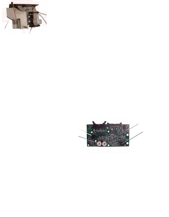
3.1.4 Machine and Proximal Pressure Transducers
The machine and proximal pressure transducers on the DA PCBA measure the machine and proximal pressure over a range of -20 to +65 cmH2O.
3.1.5 Barometric Pressure Transducer
The barometric pressure transducer on the DA PCBA measures barometric pressure over a range of 525 to 850 mmHg.
3.1.6 Oxygen Pressure Transducer
The oxygen pressure transducer on the DA PCBA measures inlet pressure over
Oxygen pressure |
Proximal |
pressure |
|
transducer |
transducer |
|
Barometric |
Machine pressure |
pressure |
transducer |
transducer |
|
DA PCBA |
a range of 0 to 87 psig. An alarm results if oxygen supply pressure is below 40 psig (276 kPa) or above 92 psig (634 kPa).
1049766 Rev A |
V60 Ventilator Service Manual |
3-3 |
Chapter 3: Theory of Operation
Oxygen filter element
3.1.7 Manifold, Oxygen Inlet Filter, Filter Element
Oxygen
inlet
filter The manifold includes a connection for the oxygen inlet, allowing countryspecific oxygen connections to be attached to the manifold. The manifold provides the pneumatic interfaces to the air inlet, oxygen inlet, blower inlet, and proximal and machine pressure lines.
 Manifold
The oxygen inlet filter removes 5-micron particles from the oxygen gas supply. A 40-micron sintered bronze filter element acts to reduce turbulence in the oxygen flow. The 40-micron oxygen breather vent reduces noise in the oxygen flow.
 Oxygen breather vent
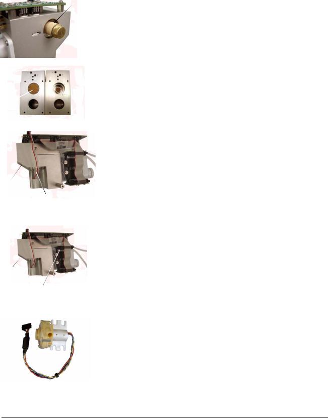
3.1.8Oxygen Solenoid Valve
The oxygen solenoid valve and valve driver circuitry control the flow of oxygen according to the set O2 and flow. The oxygen solenoid valve is closed when there is a loss of power or system reset.
Manifold
Oxygen solenoid valve
Manifold
Oxygen flow sensor
Blower
3.1.9Oxygen Flow Sensor
The oxygen flow sensor measures a subset (bypass flow) of the total flow. These measurements are interpolated according to constants that are calculated during GDS calibration. Together, the oxygen solenoid valve and flow sensor provide closed-loop control for delivered oxygen flow.
3.1.10 Blower
The blower is controlled by the MC PCBA, and generates flow and pressure for the system. The blower includes an impeller, housing, and a three-phase brushless DC motor. The blower delivers a maximum pressure of less than 125 cmH2O in a dead-head condition, can accelerate from 10,000 to 22,500 revolutions per minute (RPM) in 120 msec from a nominal 5- to 25-cmH2O pressure rise. Maximum motor speed is approximately 40,000 RPM. The blower motor has internal Hall Effect sensors that are monitored by the MC PCBA and measure impeller speed.
3-4 |
V60 Ventilator Service Manual |
1049766 Rev A |

Chapter 3: Theory of Operation
3.1.11 Solenoid Valves
Manifold
Four solenoid valves are mounted on the manifold and controlled by the DA Solenoid valves (x4) PCBA. These three-way autozero solenoids include SOL1 (purge solenoid), SOL2 and SOL4 (machine pressure autozero solenoids), and SOL3 and SOL4
(proximal pressure autozero solenoids).
Solenoid valves
SOL3, SOL4: Proximal pressure autozero solenoids. SOL4: Also connects machine pressure to the proximal pressure transducer during autozero.
SOL2, SOL4: Machine pressure autozero solenoids.
SOL1: Purge solenoid, uses the machine pressure line to purge the proximal pressure line.
1049766 Rev A |
V60 Ventilator Service Manual |
3-5 |

Chapter 3: Theory of Operation
3.2 Electronics
The electronics system provides software-based control and monitoring, power management, user input, display, subsystem I/O, external communication, and alarms. The electronics system includes a Cirrus EP9307 microcontroller for control and monitor processing.
Control tasks include breath delivery, patient data calculation, and alarm detection/response. Monitoring tasks include controlling the LCD, front panel keys and indicators, inputs, and primary alarm output. An independent watchdog control provides safety monitoring.
The electronics system includes:
•Power management (PM) PCBA
•Power supply
•Internal battery
•CPU PCBA
•Motor controller (MC) PCBA
•Data acquisition (DA) PCBA
•Flow sensors
•User interface
•Liquid crystal display (LCD)
•Backlight inverter PCBA
•Touch screen assembly
•Nav-ring assembly
•Power switch overlay
•Switch PCB
•User interface (UI) PCBA
3-6 |
V60 Ventilator Service Manual |
1049766 Rev A |
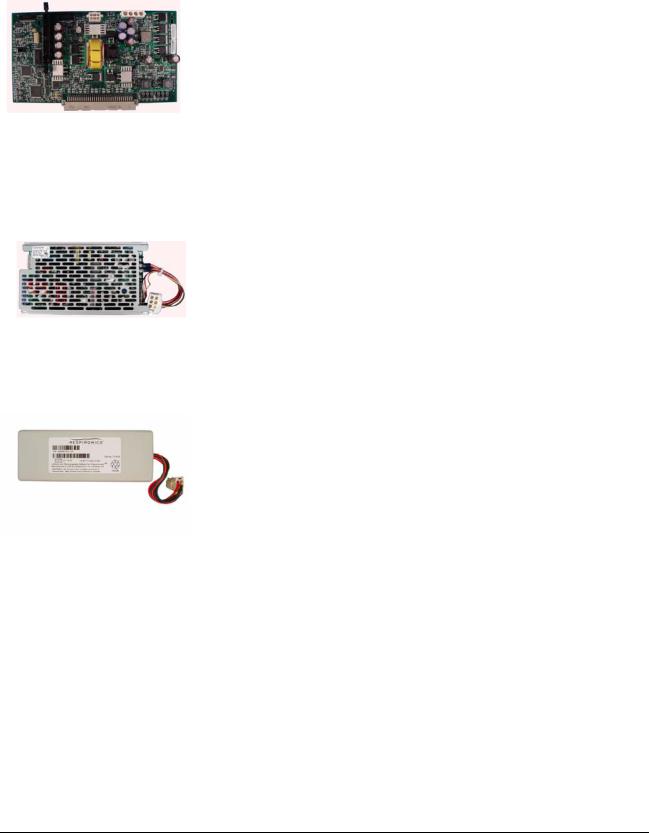
PM PCBA
Power supply
Chapter 3: Theory of Operation
3.2.1Power management (PM) PCBA
•Battery charging and management circuitry
•Internal supply voltages (supply voltages: 3.3 V, 5 V, 12 V, 35 V).
•Fan power and tach monitoring.
•Backup alarm control circuitry, including power fail detection.
•Power switch control circuitry.
•System alarm and reset management.
•Electrical interfaces between the CPU PCBA, LCD, and the user interface (UI) PCBA.
•Includes an EEPROM for calibration data, board identification information, and PM PCBA power-on hours.
3.2.2Power Supply
•Provides ventilator and battery recharging power from AC line voltage.
•Converts AC line voltage (100 to 240 VAC, 50 to 60 Hz) into 24 VDC power.
•Includes input over-current, output over-voltage, and output currentlimiting protection.
3.2.3 Internal Battery
• 14.4-V, 11.5-Ah lithium-ion battery has a run-time of at least six hours under normal conditions.
|
• Provides operating power when AC power is not available. |
Internal battery |
• Provides charge and temperature status to the PM PCBA. |
|
|
|
• Internal circuitry monitors battery status, provides self-contained |
|
fault control features, and communicates this information to the PM |
|
PCBA. |
1049766 Rev A |
V60 Ventilator Service Manual |
3-7 |

Chapter 3: Theory of Operation
3.2.4 |
CPU PCBA |
• Microprocessor: once in a run state, the microprocessor can only be |
|
|
reset by a watchdog timeout or out-of-specification power condition. |
|
Monitors operation of the ventilator and controls delivery of air and |
|
oxygen to the patient. Verifies safe ventilator operation. |
• Flash memory: 8 MB program storage. |
|
• RAM: 8 MB for program execution and volatile data storage. |
|
• EEPROM: 4 KB of storage for board-specific information (including |
|
|
operating hours, time since last service, serial numbers, part |
|
numbers, and software and hardware revisions). |
• Watchdog timer: disables the blower and oxygen flow if not strobed by |
|
CPU PCBA |
software within a predefined time window that is independent of the |
|
CPU master clock. In addition, ensures that software is operating. |
• Real-time clock (RTC): a time of day clock that provides the date and |
|
|
time to the ventilator, and is powered by a dedicated 3-V lithium coin |
|
cell battery. |
• LCD interface supports a display of 1024 horizontal x 768 vertical |
|
|
pixels in 256 colors with a refresh rate of at least 50 Hz. The CPU |
|
PCBA controls LCD brightness by varying a control voltage over a |
|
range of 0 to 3.5 V (minimum to maximum brightness). |
• Touch screen interface supports a five-wire type touch screen. |
|
• Nav-ring rotary adjustment interface with a minimum resolution of 24 ticks per revolution.
• User key switches: interfaces to front panel keys.
• Alarm subsystem: includes a speaker driver circuit for the two main speakers, a backup piezo alarm, and a three-wire relay-controlled remote alarm interface (normal open, NO, or normal closed, NC) on the ventilator back panel.
• Blower speed monitor measures blower speeds from 3,000 to 50,000 RPM with 2% accuracy.
• Electrical interfaces to the power management (PM) and motor controller (MC) PCBAs.
• Two USB ports and an ethernet connection are designed for future enhancements. Table 3-1 summarizes hospital information system (HIS) RS-232 port pinout.
3-8 |
V60 Ventilator Service Manual |
1049766 Rev A |
Loading...