


AJ-D95DCP

AJ- DCP
Digital Video Cassette Recorder
Operating Instructions
F10399W3040
D
Printed in Japan
VQT8017-3
P

2
indicates safety information.
IMPORTANT
“Unauthorized recording of copyrighted
television programs, video tapes and other
materials may infringe the right of copyright
owners and be contrary to copyright laws.”
$
Do not insert fingers or any objects into the video
cassette holder.
$
Avoid operating or leaving the unit near strong magnetic
fields. Be especially careful of large audio speakers.
$
Avoid operating or storing the unit in an excessively hot,
cold, or damp environment as this may result in
damage both to the recorder and to the tape.
$
Do not spray any cleaner or wax directly on the unit.
$
If the unit is not going to be used for a length of time,
protect it from dirt and dust.
$
Do not leave a cassette in the recorder when not in use.
$
Do not block the ventilation slots of the unit.
$
Use this unit horizontally and do not place anything on
the top panel.
$
Cassette tape can be used only for one-side, one
direction recording. Two-way or two-track recordings
cannot be made.
$
Cassette tape can be used for either Color or Black &
White recording.
$
Do not attempt to disassemble the recorder.
There are no user serviceable parts inside.
$
If any liquid spills inside the recorder, have the recorder
examined for possible damage.
$
Refer any needed servicing to authorized service
personnel.
CAUTION
RISK OF ELECTRIC SHOCK
DO NOT OPEN
CAUTION: TO REDUCE THE RISK OF ELECTRIC SHOCK,
DO NOT REMOVE COVER (OR BACK).
NO USER SERVICEABLE PARTS INSIDE.
REFER TO SERVICING TO QUALIFIED SERVICE PERSONNEL.
The lightning flash with arrowhead symbol,
within an equilateral triangle, is intended to
alert the user to the presence of uninsulated
“dangerous voltage” within the product’s
enclosure that may be of sufficient magnitude
to constitute a risk of electric shock to persons.
The exclamation point within an equilateral
triangle is intended to alert the user to the
presence of important operating and
maintenance (service) instructions in the
literature accompanying the appliance.
CAUTION:
Do not install or place this unit in a bookcase,
built-in cabinet or in another confined space
in order to keep well ventilated condition.
Ensure that curtains and any other materials
do not obstruct the ventilation condition to
prevent risk of electric shock or fire hazard
due to overheating.
WARNING:
TO REDUCE THE RISK OF FIRE OR SHOCK
HAZARD, DO NOT EXPOSE THIS EQUIPMENT
TO RAIN OR MOISTURE.
CAUTION:
TO REDUCE THE RISK OF FIRE OR SHOCK
HAZARD AND ANNOYING INTERFERENCE,
USE THE RECOMMENDED ACCESSORIES
ONLY.
CAUTION:
TO REDUCE THE RISK OF FIRE OR SHOCK
HAZARD, REFER MOUNTING OF THE
OPTIONAL INTERFACE BOARD TO
QUALIFIED SERVICE PERSONNEL.
FCC Note:
This device complies with Part 15 of the FCC Rules.
To assure continued compliance follow the attached
installation instructions and do not make any
unauthorized modifications.
This equipment has been tested and found to comply
with the limits for a class A digital device, pursuant to
Part 15 of the FCC Rules. These limits are designed to
provide reasonable protection against harmful
interference when the equipment is operated in a
commercial environment. This equipment generates,
uses, and can radiate radio frequency energy and, if
not installed and used in accordance with the
instruction manual, may cause harmful interference to
radio communications. Operation of this equipment in a
residential area is likely to cause harmful interference
in which case the user will be required to correct the
interference at his own expense.
CAUTION:
TO REDUCE THE RISK OF FIRE OR SHOCK
HAZARD, REFER CHANGE OF SWITCH
SETTING INSIDE THE UNIT TO QUALIFIED
SERVICE PERSONNEL.
3883A160

3
Contents
Introduction . . . . . . . . . . . . . . . . . . . . . . . 4
Features . . . . . . . . . . . . . . . . . . . . . . . . . . 4
Parts and Their Functions . . . . . . . . . . . . 5
Front panel . . . . . . . . . . . . . . . . . . . . . . . . . . . . . . 5
Connector areas . . . . . . . . . . . . . . . . . . . . . . . . . . 9
Example of Connections . . . . . . . . . . . . 11
Tapes . . . . . . . . . . . . . . . . . . . . . . . . . . . . 12
Types of tapes and their recording times . . . . . . 12
Operations . . . . . . . . . . . . . . . . . . . . . . . 13
Turning on the power/inserting a cassette . . . . . 13
Stop mode . . . . . . . . . . . . . . . . . . . . . . . . . . . . . 13
Recording . . . . . . . . . . . . . . . . . . . . . . . . . . . . . . 14
Pause/recording
(back-space assemble recording) . . . . . . . . . . . 14
Playback . . . . . . . . . . . . . . . . . . . . . . . . . . . . . . . 15
Cue/review . . . . . . . . . . . . . . . . . . . . . . . . . . . . . 15
Still-picture playback . . . . . . . . . . . . . . . . . . . . . . 15
Linear 0.3a speed playback . . . . . . . . . . . . . . . . 16
Variable speed playback . . . . . . . . . . . . . . . . . . 16
Audio channels . . . . . . . . . . . . . . . . . . . . . . . . . . 17
Time Codes/User’s Bit . . . . . . . . . . . . . . 19
Time codes . . . . . . . . . . . . . . . . . . . . . . . . . . . . . 19
User’s bit . . . . . . . . . . . . . . . . . . . . . . . . . . . . . . . 19
Setting the time code . . . . . . . . . . . . . . . . . . . . . 19
Setting the user’s bit . . . . . . . . . . . . . . . . . . . . . . 20
Time code/user’s bit playback . . . . . . . . . . . . . . 20
Superimposed Screens . . . . . . . . . . . . . 21
Setup (Initial Settings) . . . . . . . . . . . . . 23
Setting method using on-screen menus . . . . . . . 23
How to return to the factory settings . . . . . . . . . . 23
How to set the user defaults . . . . . . . . . . . . . . . . 24
How to load the user defaults . . . . . . . . . . . . . . . 25
How to protect the menus . . . . . . . . . . . . . . . . . . 25
How to release the menu protection . . . . . . . . . . 26
How to display the DIAG menu . . . . . . . . . . . . . 26
Setup Menus . . . . . . . . . . . . . . . . . . . . . . 27
SYSTEM menu . . . . . . . . . . . . . . . . . . . . . . . . . . 27
BASIC menu . . . . . . . . . . . . . . . . . . . . . . . . . . . . 29
OPERATION menu . . . . . . . . . . . . . . . . . . . . . . 30
INTERFACE menu . . . . . . . . . . . . . . . . . . . . . . . 31
TAPE PROTECT menu . . . . . . . . . . . . . . . . . . . 32
TIME CODE menu . . . . . . . . . . . . . . . . . . . . . . . 33
VIDEO menu . . . . . . . . . . . . . . . . . . . . . . . . . . . 35
AUDIO menu . . . . . . . . . . . . . . . . . . . . . . . . . . . 36
Error Messages . . . . . . . . . . . . . . . . . . . 38
Emergency Eject . . . . . . . . . . . . . . . . . . 39
Video Head Cleaning . . . . . . . . . . . . . . . 40
Condensation . . . . . . . . . . . . . . . . . . . . . 40
Maintenance . . . . . . . . . . . . . . . . . . . . . . 40
Specifications . . . . . . . . . . . . . . . . . . . . . 41

4
Introduction
The AJ-D95DCP is a multi-purpose digital VTR which
is capable not only of 525i/50 Mbps recording and
playback using 1/4-inch wide compact cassette tapes
but of recording and playback onto existing DVCPRO
(25 Mbps) cassette tapes as well.
This VTR with its high picture quality, which is due to
the use of digital compression technology, significantly
reduces the deterioration in the quality of both sound
and picture accompanying dubbing operations.
Its compact size and light-weight design makes it easy
for the unit to be carried around and installed in a
rack.
A dialogue system enables the unit’s settings to be
performed while monitoring the on-screen menus that
appear on the TV monitor.
Features
Compact size and lightweight
The unit is 8-7/16˝ (214 mm) wide, 5-1/4˝ (132 mm) high
and 16-15/16˝ (430 mm) deep, weighing 17.16 lb (7.8
kg).
It comes equipped with grips, which come in handy
when the unit is to be carried.
Efficient installation in a rack
The unit’s width is less than one-half of the standard
19 inches, while its height is equivalent to 3U.
This means that the unit can be installed in a rack with
twice the efficiency of previous units, a feature which
makes it economical as well.
Long-time recording and playback
When an L size cassette is used, the maximum
recording and playback time is 92 minutes in the 50
Mbps mode and 184 minutes in the 25 Mbps mode.
(using AJ-5P92LP )
Both L and M size cassettes supported
This unit employs a front loading mechanism to
support the recording or playback of DVCPRO or
DVCPRO 50 format size L and M cassette tapes.
AC or DC operation
This unit supports power supplied from both AC 120V
and DC 12V sources.
Back-space assemble recording function
By using the REC button and PAUSE button
together— a combination which activates the auto
back function— pictures can be joined smoothly with
no disturbances.
On-screen menu settings
Detailed function settings tailored to the individual
user can be performed on-screen.
Audio level controls featured
The level of the signals for the two audio channels can
be adjusted for recording and playback applications.
Time codes
Incorporated inside the unit is a TCG/TCR (time code
generator/time code reader). It is also possible to
input time codes from an external source to enable
regeneration with an external time code.
Installation of SDI connector enabled
An optional SDI input/output board (model AJ-YA95P)
for deriving the maximum from the digital VTR’s
features can be installed.
9-pin remote control
This unit comes with a 9-pin remote control connector
so that the unit can be operated using an optional
external remote controller (model AJ-A95P).
Encoder remote control
The unit’s 15-pin encoder remote control connector
enables adjustments to be made to the analog video
output section using an optional external encoder
remote controller (model AU-ER65B).
For AJ-5P92LP cassette tapes recorded using the
DVCPRO (25 Mbps) mode, use a VTR supporting
DVCPRO (25 Mbps) 184 minute tapes.
5
CH1
AUDIO OUT
25
CH1
ST
CH2
AUDIO MON SELECT
CH 3·4
50Mbps
CH2
REC
INPUT SELECT
ON
OFF
C
B
POWER
EJECT
LOCAL
MENU
ANALOG
SDI
OFF
REC INHIBIT
ON
REMOTE
PB
PULL
FOR VAR
PLAY
PAUSE/STILL
REC TAPE
EE
SET
DATA
jiMODEMENU UP
DOWNPAGE
REW STOP FF
SEARCH
RESET
COUNTER
50
WIDE
REMOTE
REC
INH
CH 1
CH 2
dB -30
-25 -20 -16 -12 -8 -4 0
-
CTL
TC
UB
HOURS MINUTES SECONDS FRAMES
SERVOSCH
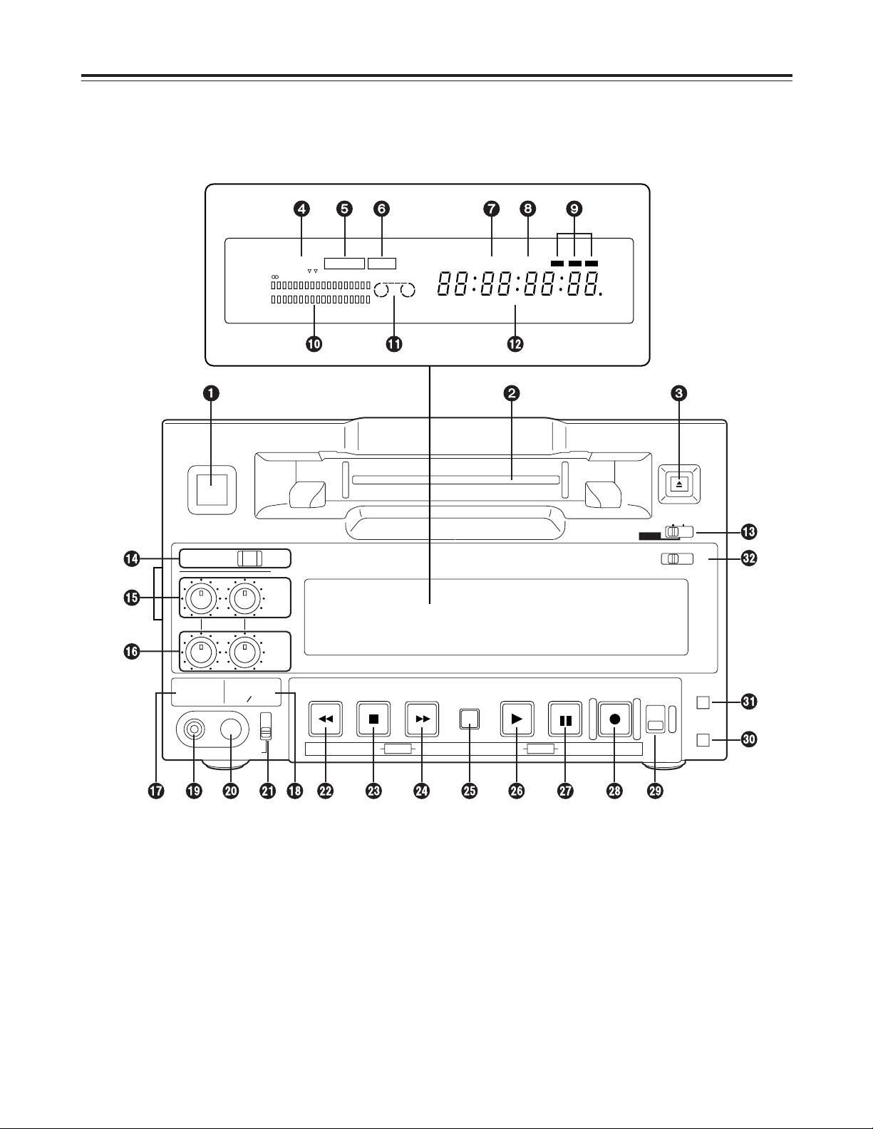
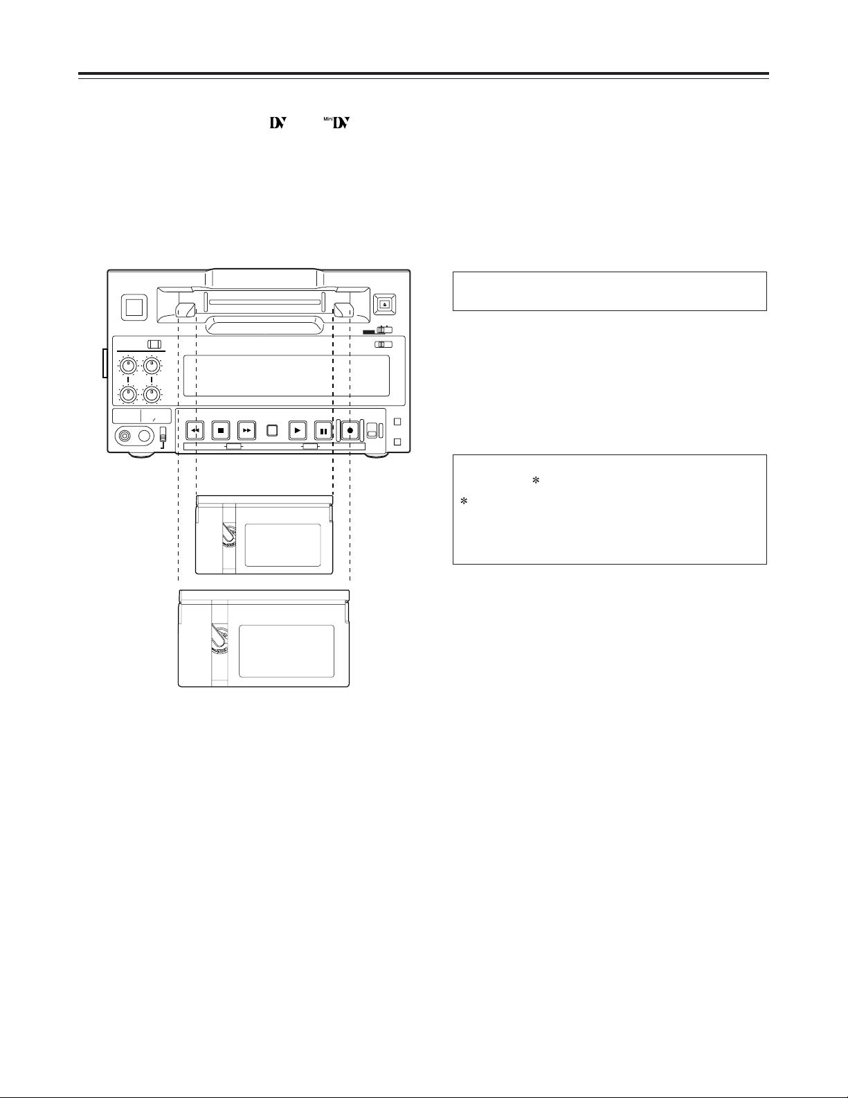
Parts and Their Functions
Front panel
Counter display area

6
Front panel
1
POWER switch
When this switch is pressed, the power is turned on
and the counter display area lights; when it is
pressed again, the power is turned off.
2
Cassette insertion slot
Newsgathering cassettes and general-purpose
cassettes are inserted into this slot.
<Note>
Do not insert DV cassettes, which are designed for
general consumer applications.
3
EJECT button
When this button is pressed, the tape inside is
unloaded and several seconds later it is
automatically ejected.
If the counter display area is set to the CTL display,
the display will be reset.
4
REC and REC INH lamps
REC:
This lamps lights during recording.
REC INH:
This lamp lights when the cassette is set
to the accidental erasure prevention
status. It also lights when the REC
INHIBIT switch Pis at the ON setting.
In this status, recording is not possible.
5
REMOTE lamp
This lamp lights when the REMOTE setting has
been selected by the LOCAL/MENU/REMOTE
switch =.
6
WIDE lamp
This lamp lights when the WIDE mode has been
selected.
7
SCH lamp
This lamp lights when the external sync signal
subcarrier phase is within the specified range.
8
SERVO lamp
This lamp lights when the drum servo and capstan
servo lock.
9
Channel condition lamps
One of these lamps lights in accordance with the
error rate statuses. (Green
Blue Red)
Green:
This lamp lights when both the error rates for
the video and audio playback signals are at
an acceptable level.
Blue:
This lamp lights when the error rate for
either the video and audio playback signals
has deteriorated. A normal playback picture
will appear even when this lamp is lighted.
Red:
This lamp lights when either the video or
audio playback signals are subject to
correction or interpolation.
:
Level meter
This displays the levels of the audio signals.
The level of the input audio signals is displayed
during recording and E-E selection; the level of the
output audio signals is displayed during playback.
;
Cassette insertion and tape travel display lamp
This lamp lights when a cassette has been inserted
into the unit.
: When a tape has been inserted and the
STANDBY ON status has been
established
: When a tape has been inserted and the
STANDBY OFF (HALF LOADING) status
has been established
: While the tape is traveling, the segment
display moves as the tape travels.
: The “” symbol at the stopped side
flashes when the fan has shut down.
<
Counter display area
The TC and CTL counts, the on-screen information
and other messages are displayed in this area.
If DC power is supplied to the unit, the whole
display will flash as a warning when the voltage has
dropped.
When the voltage drops to 10.6V or so, the power
will automatically be turned off.
=
LOCAL/MENU/REMOTE switch
This switch is set when menu settings are to be
performed or when the unit is to be controlled from
an external source.
LOCAL:
Set here when the unit is to be controlled
using the controls on its operation panel.
MENU:
Set here when on-screen menu settings
are to be performed.
REMOTE:
Set here when the unit is to be controlled
using an external remote controller
(model AJ-A95P).
Parts and Their Functions

7
>
INPUT SELECT button and lamp
This button is used to select the input signals.
Each time it is pressed, ANALOG and SDI signals
are selected alternately.
<Note>
It is not possible to select ANALOG for the video
signals and SDI for the audio signals or vice versa:
the same setting must be used for both sets of
signals.
ANALOG:
This is selected when analog composite
video signals and analog audio signals
are input. When it is selected, the
ANALOG lamp lights.
The ANALOG lamp flashes when this
setting is selected but no analog
composite video signals are input.
SDI:
SDI input signals can be selected when
the optional SDI input/output board has
been installed. When it is selected, the
SDI lamp lights. The SDI lamp flashes
when this setting is selected but no SDI
signals are input.
?
Audio signal CH1 and CH2 recording level controls
These controls are used to adjust the recording
levels of the CH1 and CH2 audio signals.
They use a “pull to vary level” system which means
that the levels can be adjusted after they have been
pulled up. The default signal levels apply when
they are pushed down.
@
Audio signal CH1 and CH2 playback level controls
These controls are used to adjust the playback
levels of the CH1 and CH2 audio signals.
They use a “pull to vary level” system which means
that the levels can be adjusted after they have been
pulled up. The default signal levels apply when
they are pushed down.
<Note>
The cue audio signal level cannot be adjusted.
A
CH3 and CH4 lamp
This lamp lights when TR3/4 is selected as the
setup menu item No.711 setting in the 50 Mbps
mode. It also lights in the E-E mode when the
optional SDI input/output board has been installed,
SDI input is selected, and CH3/4 is selected as the
setup menu item No.712 setting. (During playback,
the lamp is lighted by the No.712 setting.)
(See page 37)
B
50 Mbps lamp
This lamp lights when the 50 Mbps mode has been
established.
C
Headphones jack
When a pair of stereo headphones are connected
to this jack, the sound of the recording or playback
can be monitored through the headphones.
D
Volume control
This control is used to adjust the headphone
volume.
E
Audio monitor selector switch
This switch is used to select the audio monitor
output and headphone output channels.
CH1:
The CH1 sound is output through both the left
and right channels.
ST:
The sound selected by the settings of setup
menu items No.708 and No.709 is output.
CH2:
The CH2 sound is output through both the left
and right channels.
F
REW button
This button is pressed to rewind the tape. The
playback pictures can be monitored when the
TAPE/EE switch Mis set to TAPE.
Pressing the REW button while in the search mode
(search still, forward search, forward search still,
reverse search still) causes operation to switch to
reverse search, and reverse playback occurs at the
speed selected using setting No. 100 on the setup
menu. (See pages 15 and 30.)
Pressing the REW button while in the slow mode
(slow still, forward slow, forward slow still) causes
operation to switch to reverse linear 0.3aplayback.
(See page 16.)
Noise will appear during linear 0.3aplayback: this
is normal and not indicative of malfunctioning.
G
STOP button
This button is pressed to stop the tape travel. The
playback pictures can be monitored when the
TAPE/EE switch Mis set to TAPE.
The tape drum continues to rotate even in the stop
mode, and the tape remains in close contact with
the drum.
When the stop mode continues beyond the
prescribed period of time, the unit is automatically
set to the STANDBY OFF (HALF LOADING) mode
in order to protect the tape.
The stop mode is established immediately after a
cassette has been inserted into the unit.
Parts and Their Functions

8
Parts and Their Functions
H
FF button
This button is pressed to fast forward the tape. The
playback pictures can be monitored when the
TAPE/EE switch Mis set to TAPE.
Pressing the FF button while in the search mode
(search still, reverse search, reverse search still,
forward search still) causes operation to switch to
forward search, and fast forward playback occurs at
the speed selected using setting No. 100 on the
setup menu. (See pages 15 and 30.)
Pressing the FF button while in the slow mode
(slow still, reverse slow, reverse slow still) causes
operation to switch to forward linear 0.3aplayback.
(See page 16.)
Noise will appear during linear 0.3aplayback: this
is normal and not indicative of malfunctioning.
I
SEARCH button
This button is pressed to switch to the search mode
or the slow mode. (See pages 15 and 16.)
J
PLAY button
This button is pressed to commence playback.
Recording is commenced when it is pressed
together with the REC button.
K
PAUSE/STILL button
When this button is pressed during recording, the
tape is temporarily stopped.
Recording is resumed when it is pressed again.
When this button is pressed during playback, the
still picture mode is established. Playback is
resumed when it is pressed again.
Pressing the PAUSE/STILL button during forward
or reverse search operation causes the tape to
pause (forward or reverse search still). Pressing the
button a second time causes forward or reverse
search operation to resume.
Pressing the PAUSE/STILL button during forward
or reverse slow operation causes the tape to pause
(forward or reverse slow still). Pressing the button a
second time causes forward or reverse slow
operation to resume.
Linear 0.3aplayback takes place during forward or
reverse slow operation. Noise will appear during
still and linear 0.3aplayback: this is normal and not
indicative of malfunctioning. (See page 16.)
L
REC button
Recording is commenced when this button is
pressed together with the PLAY button. When it is
pressed in the stop or eject mode, the input video
signals and audio signals can be monitored even
when the TAPE/EE switch is set to TAPE.
It is also possible to use the button to check the
time code generator’s value. (REC CHECK mode)
When the STOP button or any other function button
is pressed, the REC CHECK mode will be released.
M
TAPE/EE switch
This switch is used to select the signals to be
output in the stop, fast forward or rewind mode.
TAPE:
The signals which are played back from the
tape are output.
EE:
The input signals which were selected by the
INPUT SELECT button are output.
<Notes>
O
When REC has been set for setup menu item
No.105, the E-E mode will be established in the
stop mode regardless of the position of the
TAPE/EE switch. (See page 30)
O
The picture and sound may break up when the
position of the switch is changed.
N
COUNTER button
This button is used to switch the counter display
area. Each time it is pressed, the setting is
changed in the following sequence: CTL
TC
UB r CTL, etc.
CTL:
The tape timer (control signal) appears on the
display.
TC:
The time code appears on the display.
UB:
The user bit appears on the display.
r: The amount of tape remaining is displayed in
1-minute increments.
(Example)
“r102” = 102 minutes of tape are remaining.
O
RESET button
When this button is pressed in the CTL mode, the
counter display is reset to 00:00:00:00.
P
REC INHIBIT button
This button is used to allow or inhibit recording onto
the cassette tape.
ON:
Recording on the cassette tape is inhibited.
The REC INHIBIT lamp on the display lights.
OFF:
Provided that the accidental erasure
prevention mechanism on the cassette tape is
set to the recording enable position, a
recording can be made on the cassette tape.
9
CH 1 CH 2AUDIO
OUT
CH 1 CH 2AUDIO
IN
REF VIDEO IN
VIDEO
IN OUT
ON
OFF
75 Ω
TC IN
TC OUT
VIDEO MON
OUT
AUDIO
MON OUT
LR
ENCODER
REMOTE
DC OUT
12V 250mA
AC IN
REMOTE
DC IN
SIGNAL
GND
FUSE 125V 2.5A
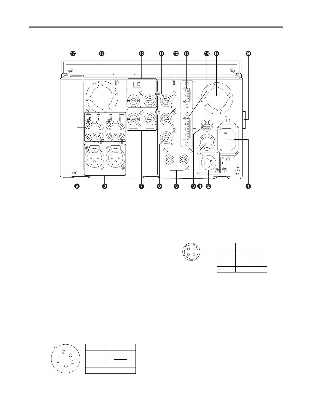
Connector areas
Parts and Their Functions
3
DC OUT socket
This is the DC 12V output connector.
It is used to supply power to the external remote
controller (model AJ-A95P).
The DC power cable is packed with the model AJA95P controller.
4
Fuse holder
This contains a 2.5A fuse.
5
AUDIO MONITOR OUT (Lch/Rch) connectors
These are the output connectors for the audio
monitor signals. It is possible to select the channel
through which the audio monitor signals are to be
output using the audio monitor selector switch on
the front panel and setup menu item No.708.
(See page 36)
3
1
2
4
Pin No. Signal
1 Ground
2
3
4 +12 V
1
2
3
4
Pin No. Signal
1 Ground
2
3
4 +12 V
1
AC IN socket
This is the AC power inlet.
The accessory power cord is connected here.
Use an AC 120V (±10%) power supply to operate
this unit.
When the voltage has dropped to an extremely low
level, the unit’s power is automatically switched off.
It will take several minutes for the unit to be reset
even after the supply voltage is restored. In a case
like this, set the POWER switch to OFF, wait
several minutes, and start up the unit again. AC
power takes precedence when both AC and DC
power supplies have been connected.
2
DC IN socket
This is the input connector for the DC 12V power.
Use the optional AC adaptor (model AJ-B75).
When the voltage has dropped to around 10.6V, the
unit’s power is automatically switched off. It will
take several minutes for the unit to be reset even
after the supply voltage is restored. AC power
takes precedence when both AC and DC power
supplies have been connected.
10
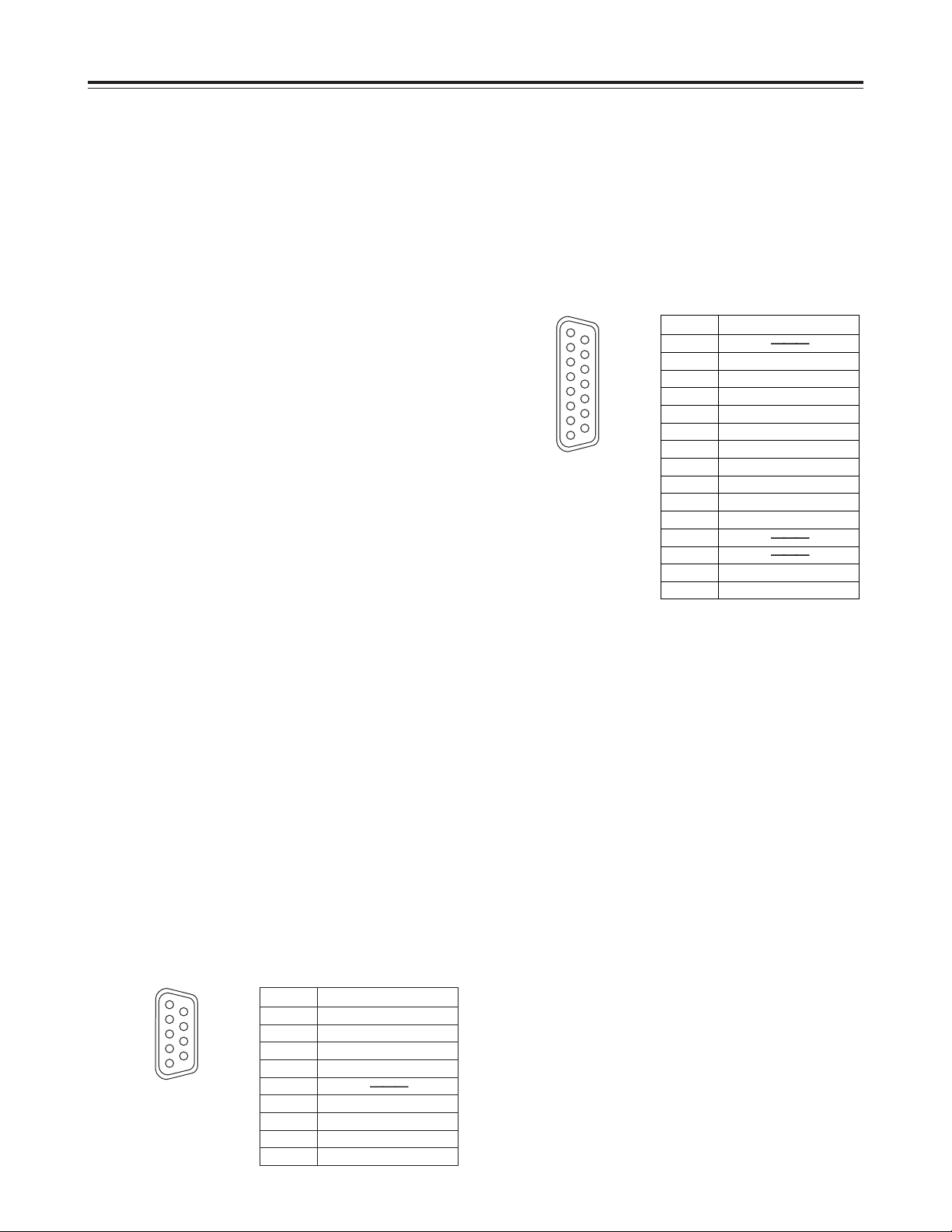
Connector area
Parts and Their Functions
Pin No. Signal
1 Frame Ground
2 Transmit A
3 Receive B
4 Receive Common
5
6 Transmit Common
7 Transmit B
8 Receive A
9 Frame Ground
1
6
9
5
Pin No. Signal
1
2 Set Up
3 C Level
4 Ground
5 +9 V
6 System H
7 SYS. SC. Coarse (2)
8 –9 V
9 Hue
10 Video Level
11 Ret Ground
12
13
14 SYS. SC. Fine
15 SYS. SC. Coarse (1)
1
8
9
15
?
Fan motor
This motor drives the fan to cool down the unit.
@
Grip
Grips are provided on the side panels. However,
when the unit is to be operated, lay it flat.
A
Slot for SDI card (option)
This is the slot for the optional component serial
interface board (SDI input/output board: model AJYA95P).
6
VIDEO MONITOR OUT connector
This is the output connector for the video monitor
signals. Superimposed video signals can be output
to this connector.
Superimposing can be set to ON or OFF by setup
menu item No.002. (See page 29)
7
VIDEO IN and OUT connectors
These are the input connector and output
connectors for the analog composite video signals.
8
AUDIO OUT (CH1/CH2) connectors
These are the output connectors for the analog
audio signals.
9
AUDIO IN (CH1/CH2) connectors
These are the input connectors for the analog audio
signals.
:
REF VIDEO IN connectors and 75 Ω termination
switch
These are the input connectors for the reference
video signals.
Input black burst signals or composite video signals
which comply with the RS-170A standard.
Set the switch to ON for termination.
;
TC IN connector
This is the connector for recording the external time
codes on the tape.
<
TC OUT connector
During playback, the playback time code is output
to this connector. During recording, the time code
generated by the internal time code generator is
output.
=
REMOTE CONTROL connector
This unit can be operated from an external source
by connecting an optional external remote controller
(model AJ-A95P) to this connector.
<Notes>
O
Set the LOCAL/MENU/REMOTE switch to the
REMOTE position.
O
This complies with the RS-422A interface
standard but the functions associated with editing
do not work.
>
ENCODER REMOTE connector
An optional external encoder remote controller
(model AU-ER65B) is connected to this connector
when the video output signal settings are to be
adjusted from an external source.
<Note>
Set setup menu item No.00 to REMOTE.
(See page 27)
11
CH 1 CH 2AUDIO
OUT
CH 1 CH 2AUDIO
IN
REF VIDEO IN
VIDEO
IN OUT
ON
OFF
75 Ω
TC IN
TC OUT
VIDEO MON
OUT
AUDIO
MON OUT
LR
ENCODER
REMOTE
DC OUT
12V 250mA
AC IN
REMOTE
DC IN
SIGNAL
GND
FUSE 125V 2.5A
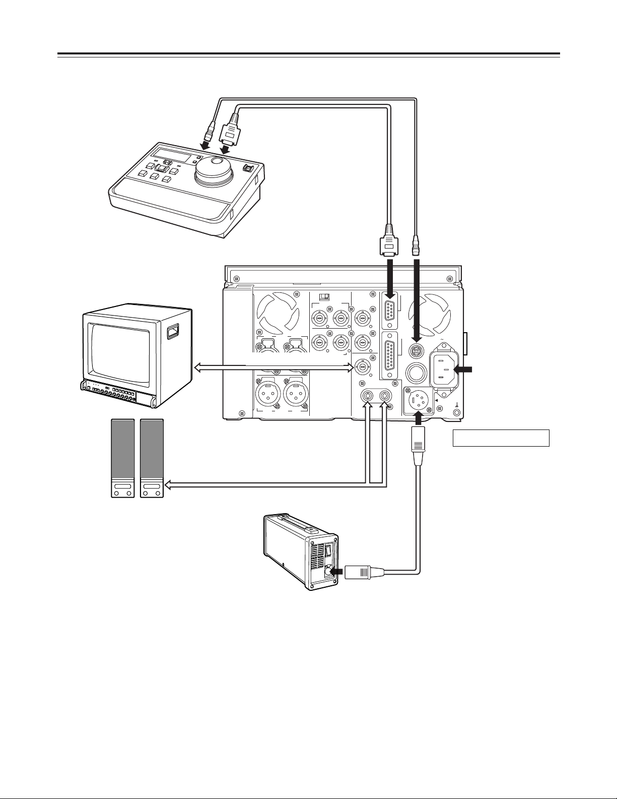
Example of Connections
Monitor
Speakers with
built-in amplifier
VIDEO MONITOR output
VIDEO MONITOR output
AC cable
(packed with unit)
AC 120V or AC adaptor
AJ-B75 (option)
4-pin DC power cable (packed with AJ-B75)
9-pin RS-422A cable (option)
4-pin DC power cable (packed with AJ-A95P)
AJ-D95DC
AJ-A95P
Video input signals and reference
video input signals
When signals are to be input simultaneously to the
VIDEO IN connectors and REF VIDEO IN connectors,
make sure that the respective signals are
synchronized.
If these signals are not synchronized, the E-E picture
may dance, the advance of the time code display may
slow down, the response to operations may slow
down or some other phenomenon may occur
(although the signals will be recorded normally).
In a case like this, a normal picture display can be
restored by setting setup menu item No.600 to VF.
(See page 35)
12
Tapes
Types of tapes and their recording
times
M size cassettes
O
50 Mbps mode
Tapes with a recording/playback length of up to
33 minutes:
O
25 Mbps mode
Tapes with a recording/playback length of up to
66 minutes:
L size cassettes
O
50 Mbps mode
Tapes with a recording/playback length of up to
92 minutes:
O
25 Mbps mode
Tapes with a recording/playback length of up to
184 minutes:
AJ-P34LP, AJ-P66LP, AJ-P94LP, AJ-P126LP,
AJ-5P92LP
For AJ-5P92LP cassette tapes recorded using
the DVCPRO (25 Mbps) mode, use a VTR
supporting DVCPRO (25 Mbps) 184 minute
tapes.
AJ-P12MP, AJ-P24MP, AJ-P33MP, AJ-P46MP,
AJ-P66MP
CH1
AUDIO OUT
25
CH1
ST
CH2
AUDIO MON SELECT
CH 3·4
50Mbps
CH2
REC
INPUT SELECT
ON
OFF
C
B
POWER
EJECT
LOCAL
MENU
ANALOG
SDI
OFF
REC INHIBIT
ON
REMOTE
PB
PULL
FOR VAR
PLAY
PAUSE/STILL
REC TAPE
EE
SET
DATA
jiMODEMENU UP
DOWNPAGE
REW STOP FF
SEARCH
RESET
COUNTOR
50
M size
cassette
L size
cassette
<Notes>
DV tapes bearing either the “” or “” logo for
regular consumer applications cannot be used. Do
not insert them into the unit.
Align the cassette with the center of the insertion slot,
and push it in gently.
Once inserted, the cassette tape is loaded
automatically.
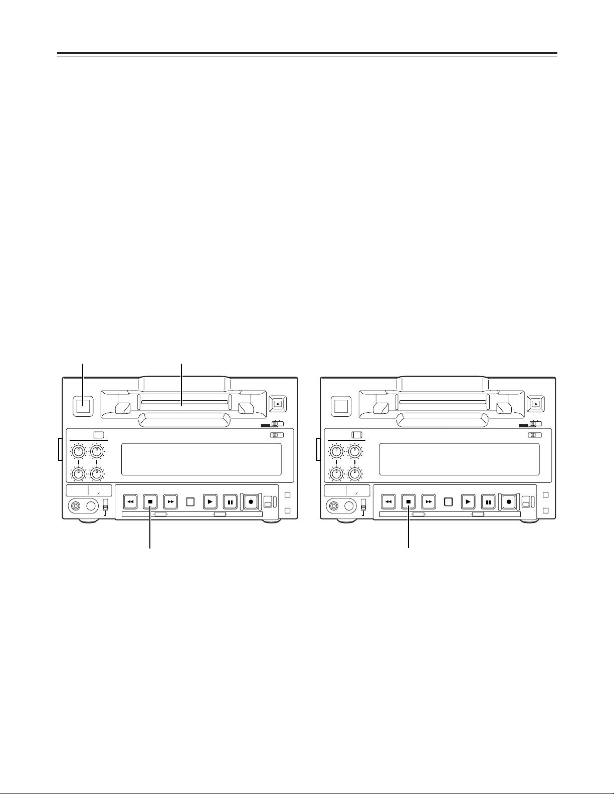
13
Stop mode
CH1
AUDIO OUT
25
CH1
ST
CH2
AUDIO MON SELECT
CH 3·4
50Mbps
CH2
REC
INPUT SELECT
ON
OFF
C
B
POWER
EJECT
LOCAL
MENU
ANALOG
SDI
OFF
REC INHIBIT
ON
REMOTE
PB
PULL
FOR VAR
PLAY
PAUSE/STILL
REC TAPE
EE
SET
DATA
jiMODEMENU UP
DOWNPAGE
REW STOP FF
SEARCH
RESET
COUNTER
50
1
CH1
AUDIO OUT
25
CH1
ST
CH2
AUDIO MON SELECT
CH 3·4
50Mbps
CH2
REC
INPUT SELECT
ON
OFF
C
B
POWER
EJECT
LOCAL
MENU
ANALOG
SDI
OFF
REC INHIBIT
ON
REMOTE
PB
PULL
FOR VAR
PLAY
PAUSE/STILL
REC TAPE
EE
SET
DATA
jiMODEMENU UP
DOWNPAGE
REW STOP FF
SEARCH
RESET
COUNTER
50
Operations
<Precaution for setting STILL TIMER>
O
At times when, for instance, the same part of the
same tape is repeatedly used, the cumulative
standby time in the same position will be increased.
In order to protect the tape, make the standby time
in the same position as short as possible.
1 2
3
Turn on the power.
1
The stop mode is established when the STOP
button is pressed.
The stop lamp lights, and the tape stops
traveling.
O
In order to protect the tape, the tape protection
mode is established after the time set in setup
menu item No.400 “STILL TIMER” has
elapsed. (See page 32)
When the STOP, REW, FF or PLAY button is
pressed, the corresponding mode is
established.
1
Insert the cassette tape.
Insert the cassette tape at the designated
position without forcing it in any way.
2
Check that the STOP lamp has lighted.
When the tape is inserted, the cylinder starts
rotating automatically, the tape is loaded, and the
stop mode is established.
3
<Note>
The STOP button flashes when no reference video
input signals are supplied if ON has been selected as
the setup menu item No.104 setting. (See page 30)
Before proceeding to operate the unit, check that it
has been connected properly.
This unit must be placed on a level surface before any
attempt is made to operate it.
Turning on the power/inserting
the cassette

14
Operations
<Notes>
O
It is not possible to select ANALOG for the video
input signals and SDI for the audio input signals or
vice versa— the same setting must be used for
both sets of signals.
O
The input signals cannot be recorded properly if a
recording inhibit signal is recorded with them.
O
Check that the SERVO lamp remains lighted during
recording. The pictures played back will be
disturbed if the lamp is flashing or off.
O
When PB has been selected as the setup menu
item No.105 setting, it will take two to three
seconds for recording to commence after the REC
and PLAY buttons have been pressed. (See page
30)
Set this menu item to REC to start the recording
faster. However, with REC set for this item, it takes
longer for the image to appear during playback after
the PLAY button is pressed.
Recording
Use the setup menu item No.007 to select
recording in either the 50 Mbps mode or 25
Mbps mode.
(See page 29)
1
Press the PAUSE/STILL button while the
cassette tape is being played.
1
Press the REC button to set the unit to the
REC PAUSE mode.
The monitor screen display now switches to the
E-E picture.
If the setup menu item No. 110 “AUTO BACK” is
set to “REC-P” or “ALL,” the tape is rewound two
to three seconds from the position at which the
PAUSE/STILL button was pressed.
(See page 31.)
2
3
Set the accidental erasure prevention tab on
the cassette to the “recording enable”
position, and insert the tape.
2
1. Selecting the input video and audio signals
1) Connect the signals that are to be
recorded.
2) Select the video and audio input signals
using the INPUT SELECT button on the
front panel.
2. Adjusting the audio levels
O
Adjust the audio input signal levels.
The audio signals are recorded at the
appropriate level when the audio recording
level controls are in the pushed-in position.
4
Press the PLAY button while holding down
the REC button.
The REC and PLAY lamps light, and recording
commences.
If the setup menu item No. 110 “AUTO BACK”
is set to “ALL,” the tape is first rewound two to
three seconds from the position at which the
REC and PLAY buttons were pressed,
advanced, and then recording starts from the
point at which the REC and PLAY buttons
were pressed. This ensures that there are no
gaps between recorded sections.
(See page 31.)
5
To stop recording, press the STOP button.
Recording now stops and the unit is set to the
stop mode.
6
Press the STOP button to set the unit to the
stop mode.
3
Pause/recording
(with back-space assemble recording)
Press the PAUSE/STILL button to start
recording.
The tape travels to the position where the
PAUSE/STILL button was pressed in step
1
, and
recording commences.
<Notes>
O
The E-E picture now appears on the screen.
O
Recording with back-space assemble
recording from the 50 Mbps mode to the 25
Mbps mode and vice versa is not possible.
Press the PAUSE/STILL button to pause
recording.
If the setup menu item No. 110 “AUTO BACK” is
set to “REC-P” or “ALL,” the tape is rewound two
to three seconds from the position at which the
PAUSE/STILL button was pressed and then
pauses.
4
Repeat steps 3and 4above to add recorded
sections with no gaps in between.
5
 Loading...