


This product is eligible for the P2HD
5 Year Warranty Repair Program. For Operating Instructions details, see page 163.
Memory Card Camera-Recorder
Model No. AG-HPX300P
Before operating this product, please read the instructions carefully and save this manual for future use.
S0109T3059 -P D |
ENGLISH |
|
Printed in Japan |
VQT2C25-3 |

Read this first! |
|
|
indicates safety information. |
|
|
CAUTION |
CAUTION: |
RISK OF ELECTRIC SHOCK |
Do not jar, swing, or shake the unit by its handle while |
DO NOT OPEN |
the conversion lens or another accessory is attached. |
|
|
|
Due to the added weight of the conversion lens, any |
CAUTION: TO REDUCE THE RISK OF ELECTRIC SHOCK, |
strong jolt to the handle may damage the unit or |
DO NOT REMOVE COVER (OR BACK). |
result in personal injury. |
NO USER-SERVICEABLE PARTS INSIDE. |
|
REFER TO SERVICING TO QUALIFIED SERVICE PERSONNEL. |
CAUTION: |
|
The lightning flash with arrowhead |
|
In order to maintain adequate ventilation, do |
|
symbol, within an equilateral triangle, is |
|
not install or place this unit in a bookcase, |
|
intended to alert the user to the presence |
|
built-in cabinet or any other confined space. |
|
of uninsulated “dangerous voltage” within |
|
To prevent risk of electric shock or fire hazard |
|
the product’s enclosure that may be of |
|
||
|
due to overheating, ensure that curtains |
||
sufficient magnitude to constitute a risk of |
|
||
|
and any other materials do not obstruct the |
||
electric shock to persons. |
|
||
|
ventilation. |
||
The exclamation point within an equilateral |
|
||
|
|
||
|
|
||
triangle is intended to alert the user to |
|
CAUTION: |
|
the presence of important operating and |
|
||
maintenance (servicing) instructions in the |
|
Do not lift the unit by its handle while |
|
literature accompanying the appliance. |
|
the tripod is attached. When the tripod is |
|
|
|
attached, its weight will also affect the unit’s |
|
WARNING: |
|||
|
handle, possibly causing the handle to break |
||
• TO REDUCE THE RISK OF FIRE OR |
|
and hurting the user. To carry the unit while |
|
SHOCK HAZARD, DO NOT EXPOSE THIS |
|
the tripod is attached, take hold of the tripod. |
|
EQUIPMENT TO RAIN OR MOISTURE. |
|
|
|
|
|
||
|
CAUTION: |
||
• TO REDUCE THE RISK OF FIRE OR SHOCK |
|
||
HAZARD, KEEP THIS EQUIPMENT AWAY |
|
EXCESSIVE SOUND PRESSURE FROM |
|
FROM ALL LIQUIDS. USE AND STORE ONLY |
|
EARPHONES AND HEADPHONES CAN |
|
IN LOCATIONS WHICH ARE NOT EXPOSED |
|
CAUSE HEARING LOSS. |
|
TO THE RISK OF DRIPPING OR SPLASHING |
|
|
|
|
|
||
LIQUIDS, AND DO NOT PLACE ANY LIQUID |
|
CAUTION: |
|
CONTAINERS ON TOP OF THE EQUIPMENT. |
|
Do not leave the unit in direct contact with |
|
|
|
the skin for long periods of time when in use. |
|
WARNING: |
|||
|
Low temperature burn injuries may be |
||
Always keep memory cards (optional |
|
||
|
suffered if the high temperature parts of this |
||
accessory) or accessories (FRONT AUDIO |
|
||
|
unit are in direct contact with the skin for |
||
LEVEL knob, knob screw, BNC cap, XLR |
|
||
|
long periods of time. |
||
connector cap, rear lens cap, zoom lever, |
|
||
|
When using the equipment for long periods |
||
connector cap) out of the reach of babies and |
|
||
small children. |
|
of time, make use of the tripod. |
|
|
|
|
CAUTION:
TO REDUCE THE RISK OF FIRE OR SHOCK
HAZARD AND ANNOYING INTERFERENCE, USE
THE RECOMMENDED ACCESSORIES ONLY.


 indicates safety information.
FCC NOTICE (USA)
Declaration of Conformity
Model Number: |
AG-HPX300P |
Trade Name: |
Panasonic |
Responsible Party: |
Panasonic Corporation of North America One Panasonic Way, Secaucus, NJ |
|
07094 |
Support contact: |
Panasonic Broadcast & Television Systems Company 1-800-524-1448 |
This device complies with Part 15 of FCC Rules. Operation is subject to the following two conditions:
(1) This device may not cause harmful interference, and (2) this device must accept any interference received, including interference that may cause undesired operation.
To assure continued compliance, follow the attached installation instructions and do not make any unauthorized modifications.
CAUTION:
This equipment has been tested and found to comply with the limits for a Class B digital device, pursuant to Part 15 of the FCC Rules. These limits are designed to provide reasonable protection against harmful interference in a residential installation. This equipment generates, uses and can radiate radio frequency energy and, if not installed and used in accordance with the instructions, may cause harmful interference to radio communications. However, there is no guarantee that interference will not occur in a particular installation. If this equipment does cause harmful interference to radio or television reception, which can be determined by turning the equipment off and on, the user is encouraged to try to correct the interference by one of the following measures:
•Reorient or relocate the receiving antenna.
•Increase the separation between the equipment and receiver.
•Connect the equipment into an outlet on a circuit different from that to which the receiver is connected.
•Consult the dealer or an experienced radio/TV technician for help.
The user may find the booklet “Something About Interference” available from FCC local regional offices helpful.
FCC Warning:
To assure continued FCC emission limit compliance, follow the attached installation instructions and the user must use only shielded interface cables when connecting to host computer or peripheral devices. Also, any unauthorized changes or modifications to this equipment could void the user’s authority to operate this device.
NOTIFICATION (Canada)
This class B digital apparatus complies with Canadian ICES-003.
IMPORTANT
“Unauthorized recording of copyrighted television programs, video tapes and other materials may infringe the right of copyright owners and be contrary to copyright laws.”
For USA-California Only
This product contains a CR Coin Cell Lithium Battery which contains Perchlorate Material – special handling may apply.
See www.dtsc.ca.gov/hazardouswaste/perchlorate.
A rechargeable battery that is recyclable powers the product you have perchased.

Precautions for Use
Caution regarding laser beams
The MOS sensor may be damaged if it is exposed to laser light.
When using the camera-recorder in locations where laser irradiation equipment is used, be careful not to allow the laser beam to shine directly on the lens.
PLEASE NOTE:
When preparing to record important events, always shoot some advance test footage, to verify that both pictures and sound are being recorded normally.
Should video or audio recording fail due to a malfunction of this camera-recorder or the P2 cards used, we will not assume liability for such failure.
Disposing and transferring ownership of memory card devices
Formatting or deleting a memory card device in this camera or a PC will only change file management data and leave data on the card intact. It is recommended that the card either be physically destroyed or that commercially sold software be used to completely delete any data on the card. Note that managing card data is the owner’s responsibility.
Information on software for this product
1.Included with this product is software licensed under the GNU General Public License (GPL) and GNU Lesser General Public License (LGPL), and users are hereby informed that they have the right to obtain, change and redistribute the source codes of this software.
Details on GPL and LGPL can be found on the installation CD provided with the unit. Refer to the folder called “LDOC”. (Details are given in the original (English-language) text.)
To obtain the source codes, go to the following home page: https://eww.pavc.panasonic.co.jp/pro-av/
The manufacturer asks users to refrain from directing inquiries concerning the source codes they have obtained and other details to its representatives.
2.Included with this product is software which is licensed under MIT-License.
Details on MIT-License can be found on the installation CD provided with the unit. Refer to the folder called “LDOC”. (Details are given in the original (English-language) text.)
This product is licensed under the AVC Patent Portfolio License for the personal and non-commercial use of the following activities of a consumer but no license is granted or implied for any other use.
Encode video in compliance with the AVC standard (“AVC video”)
Decode AVC video that was encoded by a consumer engaged in a personal and non-commercial activity.
Decode AVC video that was obtained from a video provider licensed to provide AVC video
Additional information may be obtained from MPEG LA, LLC (http://www.mpegla.com).
Trademarks
The SD and SDHC logos are trademarks.
Multi Media Card (MMC) is a registered trademark of Infineon Technologies AG.
Apple, Macintosh, Mac OS are registered trademarks or trademarks of Apple, Inc. in the United States and/or other countries.
Unislot is a registered trademark of Ikegami Tsushinki Co., Ltd.
Microsoft and Windows are registered trademarks or trademarks of Microsoft Corporation in the United States and/or other countries.
Other names of companies and products are trademarks or registered trademarks of the respective companies.

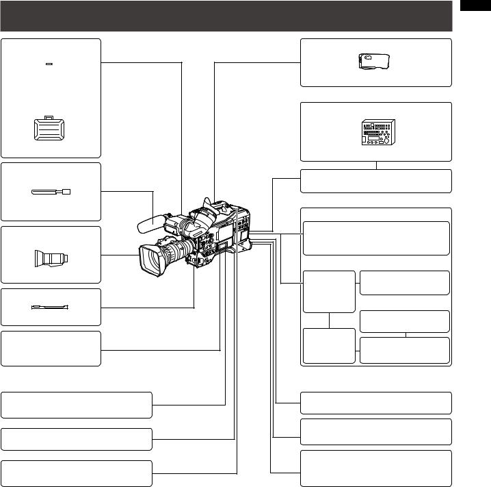
Contents
Read this first! .................................................................................................................. |
2 |
Precautions for Use ......................................................................................................... |
4 |
Chapter 1 Overview
Camera Unit Features ...................................................................................................... |
8 |
Recording and Playback Features ................................................................................ |
10 |
Outline of operations ..................................................................................................... |
12 |
Saving and editing on external devices ................................................................ |
12 |
System Confiiguration .................................................................................................... |
13 |
Standard accessories .................................................................................................... |
14 |
Chapter 2 Parts and Their Functions
Power Supply and Accessory Mounting Section .................................................. |
15 |
Audio (input) Function Section .............................................................................. |
16 |
Audio (output) Function Section ............................................................................ |
17 |
Shooting and Recording/Playback Functions Section .......................................... |
18 |
Menu/Thumbnail Operation Section ...................................................................... |
22 |
Time Code Section ................................................................................................ |
23 |
Warning and Status Display Functions .................................................................. |
24 |
LCD Monitor ........................................................................................................... |
24 |
Viewfinder .............................................................................................................. |
25 |
Chapter 3 Recording and Playback
Setting Date and Time of Internal Clock ........................................................................ |
26 |
P2 Cards ........................................................................................................................ |
28 |
Inserting P2 Cards ................................................................................................. |
28 |
Removing P2 Cards ............................................................................................... |
28 |
To Prevent Accidental Erasure of P2 Card Content ............................................... |
29 |
P2 CARD ACCESS LED and status of P2 cards ................................................... |
29 |
P2 card recording times ........................................................................................ |
30 |
Handling P2 Card Recording ................................................................................ |
31 |
Basic Procedures .......................................................................................................... |
32 |
Shooting ................................................................................................................. |
33 |
Normal Recording ................................................................................................. |
33 |
Standard and Native Recording .................................................................................... |
34 |
Standard recording (pull-down recording) ............................................................ |
34 |
Native recording .................................................................................................... |
34 |
Variable Frame Rate (VFR) Recording .......................................................................... |
35 |
Native VFR Recording ........................................................................................... |
35 |
Standard VFR recording(pulldown recording) ....................................................... |
35 |
Using VFR Recording Function ............................................................................. |
36 |
Special Recording Modes ............................................................................................. |
38 |
Pre-recording (PRE REC) ...................................................................................... |
38 |
Interval recording (INTERVAL REC) ...................................................................... |
39 |
One-shot recording (ONE SHOT REC) .................................................................. |
39 |
Loop recording (LOOP REC) ................................................................................. |
40 |
PROXY Recording Function (Optional) ................................................................. |
40 |
Hot Swap Recording ............................................................................................. |
40 |
REC REVIEW Function ........................................................................................... |
40 |
Shot Marker (SHOT MARK) Recording Function ................................................... |
41 |
Text Memo Recording Function ............................................................................. |
41 |
Normal and Variable Speed Playback .......................................................................... |
42 |
Chapter 4 Adjustments and Settings for Recording
Selecting recording signals ................................................................................... |
43 |
List of recording formats and functions ................................................................. |
44 |
Recording settings and recording function table .................................................. |
45 |
Selecting video output ........................................................................................... |
45 |
List of recording, playback and output formats .................................................... |
46 |
Adjusting the White Balance and Black Balance .......................................................... |
48 |
Adjusting the White Balance ................................................................................. |
48 |
Adjusting the Black Balance ................................................................................. |
49 |
Setting the Electronic Shutter ........................................................................................ |
51 |
Setting the Shutter Mode and Speed .................................................................... |
51 |
Placing the Camera-recorder in SYNCHRO SCAN Mode ..................................... |
51 |
FBC (Flash Band Compensation) Function ................................................................... |
52 |

Setting FBC function .............................................................................................. |
52 |
Assigning functions to USER buttons ............................................................................ |
53 |
Selecting Audio Input Signals and Adjusting Recording Levels ................................... |
54 |
Selecting Audio Input Signals ............................................................................... |
54 |
Adjusting Recording Levels .................................................................................. |
54 |
Selecting Function for the FRONT AUDIO LEVEL Control .................................... |
55 |
CH3 and CH4 Recording Levels ........................................................................... |
55 |
Setting Time Data .......................................................................................................... |
56 |
Recording time codes and user bits ..................................................................... |
57 |
Setting user bits ..................................................................................................... |
58 |
Entering the User Bits ............................................................................................ |
58 |
Setting the Time Code ........................................................................................... |
60 |
Externally Locking the Time Code ......................................................................... |
62 |
Outputting the time code externally ...................................................................... |
63 |
GENLOCK and time code input/output connection and setup ............................. |
64 |
Counter Setting and Display .................................................................................. |
64 |
Viewfinder Screen Status Displays ................................................................................ |
65 |
Viewfinder Status Indication Layout ...................................................................... |
65 |
Selecting Viewfinder Display Information .............................................................. |
65 |
Screen displays ..................................................................................................... |
66 |
Center Information Display .................................................................................... |
69 |
Checking and displaying shooting status ............................................................. |
71 |
MODE CHECK indication ...................................................................................... |
72 |
Center marker display ........................................................................................... |
73 |
Safety zone markers .............................................................................................. |
73 |
Audio level meter magnification ............................................................................ |
73 |
Zebra pattern display ............................................................................................ |
74 |
Focus assist function ............................................................................................. |
75 |
Adjusting and setting the LCD monitor ......................................................................... |
76 |
Waveform monitor function .................................................................................... |
77 |
Adjusting and Setting up the Viewfinder ....................................................................... |
78 |
Adjusting Right and Left Viewfinder Position ......................................................... |
78 |
Diopter Adjustment ................................................................................................ |
78 |
Using the Viewfinder .............................................................................................. |
78 |
Emphasizing Image Outlines ................................................................................. |
79 |
Setting the viewfinder to monochrome mode ........................................................ |
79 |
Handling setup data ...................................................................................................... |
80 |
Configuration of setup data files ............................................................................ |
80 |
Handling SD memory cards .................................................................................. |
81 |
Formatting, Writing and Reading an SD memory card ......................................... |
81 |
How to Use Scene File Data .................................................................................. |
82 |
Saving scene files and other settings on SD memory cards ................................. |
84 |
Chapter 5 Preparation
Power Supply ................................................................................................................. |
86 |
Mounting the Battery and Setting the Battery Type ............................................... |
86 |
Use of the external DC power supply .................................................................... |
88 |
Mounting and Adjusting the Lens .................................................................................. |
89 |
Mounting the Lens ................................................................................................. |
89 |
Adjusting the Lens Flange Back ............................................................................ |
90 |
White Shading Compensation ............................................................................... |
91 |
Setting Chromatic Aberration Compensation (CAC) ............................................ |
92 |
Preparing for Audio Input .............................................................................................. |
95 |
When Using the Front Microphone ........................................................................ |
95 |
Using a wireless receiver ....................................................................................... |
95 |
When Using Audio Devices ................................................................................... |
96 |
Attaching Accessories ................................................................................................... |
97 |
Mounting the Camera on a Tripod ......................................................................... |
97 |
Attaching the Shoulder Strap ................................................................................ |
97 |
Attaching the Rain Cover ....................................................................................... |
98 |
Attaching the FRONT AUDIO LEVEL Control Knob .............................................. |
98 |
Attaching the Eye Cup ........................................................................................... |
98 |
DC OUT Connector and External REC Start/Stop Switch Connection .......................... |
99 |
Connecting the AJ-RC10G Remote Controller ............................................................ |
100 |
Chapter 6 Manipulating Clips with Thumbnails
Thumbnail Operations ................................................................................................. |
101 |
Thumbnail Manipulations Overview ..................................................................... |
101 |

Thumbnail Screen ................................................................................................ |
102 |
Selecting Thumbnails .......................................................................................... |
104 |
Playing back Clips ............................................................................................... |
104 |
Switching the Thumbnail Display ........................................................................ |
105 |
Changing thumbnails .......................................................................................... |
106 |
Shot Mark ............................................................................................................. |
106 |
Text Memo ........................................................................................................... |
107 |
Deleting Clips ...................................................................................................... |
108 |
Restoring Clips .................................................................................................... |
109 |
Reconnection of Incomplete Clips ...................................................................... |
109 |
Copying Clips ...................................................................................................... |
109 |
Setting of Clip Meta Data ..................................................................................... |
110 |
Setting of Proxy (optional) ................................................................................... |
114 |
Formatting a P2 Card .......................................................................................... |
114 |
Formatting SD memory cards .............................................................................. |
115 |
Setting the Thumbnail Display Mode ................................................................... |
115 |
Properties ............................................................................................................ |
116 |
Chapter 7 Menu Operations
Viewfinder and LCD Menus ......................................................................................... |
120 |
Using the menus .................................................................................................. |
120 |
Initializing the menu settings ............................................................................... |
121 |
Setup menu structure .................................................................................................. |
122 |
Setup menu list ............................................................................................................ |
124 |
SCENE FILE screen ............................................................................................. |
124 |
SYSTEM SETUP screen ....................................................................................... |
126 |
SW MODE screen ................................................................................................ |
128 |
RECORDING SETUP screen ............................................................................... |
129 |
AUDIO SETUP screen ......................................................................................... |
130 |
OUTPUT SEL screen ........................................................................................... |
132 |
DISPLAY SETUP screen ...................................................................................... |
132 |
BATTERY SETUP screen ...................................................................................... |
134 |
CARD FUNCTIONS screen ................................................................................. |
136 |
LENS SETUP screen ............................................................................................ |
136 |
OTHER FUNCTIONS screen ............................................................................... |
137 |
DIAGNOSTIC screen ........................................................................................... |
138 |
OPTION MENU screen ........................................................................................ |
138 |
Chapter 8 Connecting to External Devices
Functionality Provided by Connections to USB 2.0 Connector ................................... |
139 |
Connecting to a computer in USB device mode ................................................. |
139 |
USB host mode ................................................................................................... |
140 |
Connections to the DVCPRO/DV Connector ............................................................... |
145 |
Recording signals input to the DVCPRO/DV connector ...................................... |
145 |
Control of external devices through 1394 connection ......................................... |
146 |
Chapter 9 Maintenance and Inspections
|
Inspections Before Shooting ....................................................................................... |
147 |
|
Preparing for Inspections .................................................................................... |
147 |
|
Inspecting the Camera Unit ................................................................................. |
147 |
|
Inspecting the Memory Recording Functions ..................................................... |
148 |
|
Maintenance ................................................................................................................ |
150 |
|
Eyepiece Care ..................................................................................................... |
150 |
|
Cleaning Inside the Viewfinder ............................................................................ |
150 |
|
Charging the internal battery ............................................................................... |
150 |
|
Warning System ........................................................................................................... |
151 |
|
Warning Description Tables ................................................................................. |
151 |
|
Warning and Error Display for Thumbnail Operation and USB HOST MODE ..... |
153 |
|
Updating the firmware incorporated into the unit ........................................................ |
155 |
|
|
|
Chapter 10 Index |
|
|
|
|
|
Chapter 11 Specifications |
|
|
|
Dimensions and specifications .................................................................................... |
160 |
|
Dimensions .......................................................................................................... |
160 |
|
Specifications ...................................................................................................... |
160 |
|
Connector signal description ...................................................................................... |
164 |

Overview Chapter 1
Chapter 1 Overview
The AG-HPX300P P2 memory card camera-recorder features a camera unit equipped with a 1/3 inch 2.2 megapixel 3MOS sensor and a recording and playback unit that provides AVC-Intra 100 compression recording as standard to offer HD full pixel and full sampling for superb image quality and high-quality video.
It handles multiple HD and SD formats: AVC-Intra, DVCPRO HD, DVCPRO50, DVCPRO and DV compression recording. The P2 card provides a reliability, speed and IT functionality that no other media can match and is destined to revolutionize recording and editing paradigms.
Multiple HD/SD formats
The camera supports both the HD and SD video formats making it ready for news gathering, program production and film making in a wide range of professional applications and content production. In 1080i/720P HD recording for broadcasting, the camera uses the highly reliable AVC-Intra or DVCPRO HD codec while also supporting SD multicodec (DVCPRO50, DVCPRO or DV) recording capability.
The AG-HPX300P provides high quality and uncompressed, 16-bit, 48 kHz, 4-channel recording of audio in all formats.
Variable frame rate makes speed effects possible (in the 720P format)
The AG-HPX300P comes with the variable frame rate feature developed for the VariCam HD Cinema camera. In 720P mode *1, the frame rate can be set to any of 20 steps between 12P and 60P. This puts features such as undercranking (dropping frames) and overcranking (high frame rate) for quick motion and slow motion cine-like effects at the disposal of the camera crew.
Native mode/over 60P mode selectable
Native mode:
Playing back a recording made at a frame rate set in the camera at the normal rate provides speed effects without using a frame rate converter. Native mode also extends the recording time of a P2 card.
720P over 60P mode:
Use of a DVCPRO HD recorder such as the AJ-HD1400 or the FOCUS FS-100 hard disk recorder enables the AGHPX300P to make backup recordings with a DVCPRO HD stream from the DVCPRO/DV connector. *2
1080/480 24P advanced mode
Recording 1080/24P or 480/24P makes it possible to select 24PA (advanced) mode *3. Using 2:3:3:2 pulldown, the 24PA mode performs 60i conversion to enable nonlinear editing *4 maintaining an image quality that is better than normal 24P (2:3 pulldown). Recording at 30P applies a 2:2 pulldown.
Camera Unit Features
Progressive 3MOS sensor
The AG-HPX300P is equipped with a 1/3 inch 2.2 megapixel 3MOS sensor that enables HD full pixel recording for highresolution video.
14-bit digital circuit
The high-performance DSP (Digital Signal Processor) in the camera offers 14-bit signal input and 20-bit internal processing. It handles gamma settings and other adjustments for each R/G/B color in 1080/60i video as well as conversion to all HD/SD formats (P/I conversion, line conversion and down conversion). Because of this high-quality images can be produced in all video formats.
Seven gamma curves including cine-like gamma
To expand camera capabilities, the AG-HPX300P offers seven gamma curves including cine-like gamma to easily produce recordings with the characteristic warm tone of film.
*1 1080 and 480 recording is performed at a fixed frame rate of 24P/30P.
*2 The AVC-Intra mode does not allow the output of a DVCPRO HD stream from the DVCPRO/DV connector. *3 Not available with the AVC-Intra codec.
*4 For details on compatible systems, visit the Web site listed below. https://eww.pavc.panasonic.co.jp/pro-av/
24P and 30P indicate recording at 23.98P and 29.97P, respectively, while 60P and 60i indicate recording at 59.94P and 59.94i, respectively.

Slow, synchro and high speed shutter
The shutter speed can be set from a slow speed of 1/6 s up to a maximum speed of 1/7200 s *1. Combined with the variable frame rate functions, this allows you to create blurring or stop motion effects. The AG-HPX300P also features a synchro scan function that is ideal for capturing screen shots from a computer monitor.
Scene file dial
This dial allows you to instantly retrieve settings that suit shooting conditions. Six preset files are provided, and you can change the file names and their settings as desired. You can also save up to four files to an SD or SDHC memory card (both referred to as “SD memory card” below) and load files from an SD memory card.
Shooting assist functions
USER buttons:
Three USER buttons each of which can be assigned a frequently used function for immediate access.
Focus assist:
Magnifies the center portion of the image and displays a focus bar to facilitate focusing.
Eight files for compensating lens chromatic aberration and four files for correcting shading for interchangeable lenses are provided.
Variable color temperature:
Allows fine adjustment after setting the white balance.
REC REVIEW:
Provides a quick check of the last few seconds of the most recently recorded clip.
4-position optical ND filter provided.
Chromatic aberration compensation (CAC)
This function automatically corrects the registration error caused by the slight chromatic aberration that the lens cannot compensate for, in order to minimize color bleeding into surrounding image areas.
Remote control support
The camera supports the AJ-RC10G (optional accessory) remote control unit. The remote control allows you to adjust camera image and recording controls at a distance while viewing what you are shooting.
Auto Tracking White Balance (ATW)
Automatically adjusts the white balance of the subject in real-time, a convenient function for quick adjustment in recording situations where there is no time for normal white balance adjustment.
DRS (Dynamic Range Stretcher) function
This function compresses the video signal level while maintaining contrast to extend the dynamic range making it possible to correctly render highlight areas without overexposure and loss of detail that would otherwise occur. *2
*1 This is the shutter speed value when 3.0d is configured for the synchro scan mode. *2 The DRS function is not available in 1080/30P, 1080/24P modes.
Overview Chapter 1

Overview Chapter 1
Recording and Playback Features
A variety of interfaces
USB 2.0 connector (HOST/DEVICE)
A USB 2.0 connection to a computer or other device allows you to use P2 cards in the camera as mass storage. The USB host function makes it possible to save P2 card data to an external hard disk connected via USB 2.0 and clips stored on the hard disk can be viewed and written back to a P2 card.
DVCPRO/DV input and output provided as standard feature
IEEE1394 compliant external devices can be connected to enable output and input via the digital interface. Connect a 6-pin plug to this connector. Note that the connector does not support bus power.
Input and output via IEEE1394 is not available when the AVC-Intra codec is selected.
P2 cards for high capacity, high speed and high reliability
In addition to exceptional resistance to shock, vibration and temperature fluctuations, the P2 (Professional Plug-in) card has a reliability that guarantees long-term repeated recording/initialization that a tape or hard disk system with their moving parts could never match.
The connectors are professional grade to withstand long-term continual insertion and removal.
The P2 card stores the AV data for each shooting session as a single file that is immediately accessible for nonlinear editing or transfer over a network without digitizing. Transfer speeds far surpassing those of optical disks also help to speed up production processes. The P2 card complies with PC card standards and can be directly plugged into the PC card slot on a computer. *1
The two P2 card slots allow continuous recording on two P2 cards and also offer the following recording capabilities in a memory card camera-recorder.
Card selection:
In standby status, you can instantly select (switch to) the slot of the card you wish to record on *2 Recorded content can be quickly passed on to editing or transferred to minimize interruptions in recording making it far more efficient than systems where tapes or disks have to be exchanged.
Hot-swap recording:
Cards can be replaced during recording. A full memory card can be replaced while recording is made on another card. Successively swapping cards in this way gives you virtually unlimited recording capacity.
Loop recording:
Setting the camera for consecutive overwriting, you can repeatedly rerecord on the inserted P2 cards, always maintaining a recording of the most recent, specific period of time.
Immediate startup and reliable data protection
When you press the REC button in standby mode, the camera instantly finds a blank area on the P2 card and begins recording. Unlike a VTR system, there is no need to locate a blank section before recording. It can begin recording immediately even when you are using it to preview video. In normal use, there is no chance of accidentally deleting a recording. Recordings will not be erased unless you intentionally delete a file or initialize the card.
*1 This requires the installation of a P2 card driver (provided with each device). The P2 card driver runs under Windows® Vista, Windows® XP or Windows® 2000.
*2 This assumes that the SLOT SEL function is assigned to a USER button (USER MAIN, USER1 or USER2).
10
Other features
Pre-rec:
This function provides a way to capture moments you otherwise would have missed. In the standby mode, the camera will store video and audio for up to 3 seconds in HD and 7 seconds in SD. When you press the REC button, the three or seven seconds of immediately prior video data stored in internal memory is added at the beginning of the clip you record.
One-shot REC:
Convenient for producing animation, this mode records for a set time (from 1 frame to 1 second) each time you press the REC button.
Interval REC:
Recording one frame at a time at set intervals (from 2 frames to 10 minutes), this mode is useful for monitoring, supervision and special ultra undercranking effects.
Proxy recording (with AJ-YAX800G installed)
Installing an optional video encoder card (AJ-YAX800G) in P2 slot number 2 makes it possible to record MPEG4 format video, time code data and other real-time data to P2 cards or SD memory cards simultaneous with camera recording of video and audio. This is a convenient feature for checking clip content and speeding up editing work flow.
Clip thumbnail preview
The camera records each cut as a clip (file) and automatically attaches a thumbnail image and file information to it. To preview a clip on the LCD monitor or to check clip data, simply choose the clip you want from the list of thumbnails. These thumbnails and the file data can be viewed on a PC (P2 Viewer *1) or processed in a nonlinear editing program.
Shot marker and text memo
If desired, you can add a simple OK/reject shot marker to each clip either during or after recording. When a P2 card is mounted in a PC (P2 Viewer), the PC will display only marked clips.
A text memo function is also provided. Pressing the USER button to which the text memo function has been assigned anywhere in a clip during recording or in preview mode allows you to attach empty post-it like text memos (up to 100) that can later be filled with text on a PC (P2 Viewer).
Using the camera copy function, you can create a new clip by stripping out the desired frames from a clip by copying data between text memo labels.
SD memory card slot
The camera provides an SD memory card slot for saving and loading scene files and user settings. A metadata upload file (created using P2 Viewer) containing the name of the person who shot the video, the name of the reporter, the shooting location or a text memo and other information can be saved to an SD memory card. This data file can be loaded as clip metadata.
HD/SD SDI output and downconverter supported
Video line outputs (3 BNC connectors) are provided as standard. These outputs can flexibly handle both monitor and line recording. A down-converter is also built-in. Aspect mode can also be selected.
SDI OUT (HD/SD) 1 system, 2 outputs:
The HD-SDI outputs allow you to make backups on an external VTR (with HD-SDI input) in synch with REC button operation. SD-SDI can also down convert and output HD content.
VIDEO OUT:
Outputs down converted SD video (composite video).
Fine adjustment of sound recording level
The camera features a front-mounted control for fine adjustment of the sound recording level. This control is particularly useful for adjusting the sound level when you have to control both video and audio recording. The control can be disabled.
Unislot wireless receiver compatible
The AG-HPX300P is designed to work with optional slot wireless receivers. (page 95) The camera supports 2-channel wireless receivers.
*1 “P2 Viewer” is a Windows® PC viewing software that can be downloaded free of charge by P2 card users.
Overview Chapter 1
11

Overview Chapter 1
Outline of operations
The AG-HPX300P records video on P2 cards. Excelling at high transfer speeds, the P2 card enables high vision recording and smooth editing and dubbing.
Saving and editing on external devices
Using USB DEVICE mode to connect an external device via the USB 2.0 connector (Page 139)
The data (file) is transferred for nonlinear editing on your computer or other unit.
P2 card |
Computer |
||||
|
|
|
|
|
|
|
|
|
|
|
|
|
|
|
|
|
|
|
|
|
|
|
|
USB2.0 (DEVICE)
Using USB HOST mode to connect an external device via the USB 2.0 connector (Page 140)
The unit directly controls the external hard disk drive, and transfers the data (file) to it.
External hard disk
USB2.0 (HOST)
|
Connecting an external device via the |
||
|
DVCPRO/DV connector (Page 145) |
||
DVCPRO/DV |
Computer/Memory card recorder |
||
(Windows/Macintosh) |
|||
|
|
|
|
|
|
|
|
Video equipment/Monitor
BNC cable (composite/SDI)
The contents can be transferred as a data stream (digital dubbing).
12
System Configuration
Soft carrying case |
Rain cover |
 SHAN-RC700 AJ-SC900
Hard carrying case
Remote control unit *5
AJ-HT901G |
AJ-RC10G |
|
Shotgun microphone |
Remote control cable |
||
(Phantom +48 V) |
|||
|
AJ-C10050G |
||
|
|
||
AG-MC200G |
|
|
|
AJ-MC700P |
|
Battery |
|
|
|
||
Lens *2 |
*1 PROPAC14, TRIMPAC14 |
||
(Bayonet type) |
HYTRON50/140 |
||
DIONIC90/160 |
|||
|
|||
FUJINON, CANON |
V-mount |
ENDURA E-7/7S |
|
AG-HPX300P |
type |
ENDURA E-10/10S |
|
Tripod adapter |
battery |
|
|
|
plate |
|
|
SHAN-TM700 |
|
NP-L7 |
|
|
|
||
Video encoder card |
Holder |
|
|
plate *6 |
NP battery holder |
||
AJ-YAX800G *4 |
|||
SD Memory cards *3 |
External power supply |
||
P2 Cards *3 |
|
|
|
|
|
LCD monitor |
|
USB2.0 compatible devices |
BT-LH80W, BT-LH900 etc. |
||
|
DVCPRO/DV standard device |
||
Unislot wireless |
|
complying with |
|
microphone receiver |
the IEEE1394 standard |
||
*1 The camera is equipped with a battery holder as standard. *2 The camera comes with a Fujinon lens.
*3 For the latest information on P2 cards and SD memory cards not available in the operating Instructions, visit the P2 Support Desk at the following Web sites.
https://eww.pavc.panasonic.co.jp/pro-av/
*4 For details, refer to the AJ-YAX800G User’s Guide on the supplied CD-ROM. *5 For details, refer to the AJ-RC10G User’s Guide on the supplied CD-ROM.
*6 Attach the NP battery holder to the holder plate before fixing it to the V-mount type battery plate.
Overview Chapter 1
13

Overview Chapter 1
Standard accessories
Lens *1 |
Front lens cap *1 *2 |
Rear lens cap *1 *2 |
Zoom lever *1 *2 |
|
|
|
|
|
|
|
|
|
|
|
For details, refer to |
|
|
|
[Mounting the Lens] |
|
|
|
(page 89). |
|
|
|
Connector cap *1 *2 |
Lens hood *1 |
Lens hood cap *1 *3 |
Eye cup |
|
|
For details, refer to |
|
|
[Attaching the Eye Cup] |
|
|
(page 98) |
Shoulder belt |
FRONT AUDIO LEVEL knob Mount cap *4 |
XLR connector cap *4 |
|
(screw included) |
|
|
For details, refer to |
For details, refer to |
[Attaching the FRONT |
[Attaching the Shoulder |
AUDIO LEVEL Control |
Strap] (page 97). |
Knob] (page 98). |
BNC cap *4 |
CD-ROM |
*1 Manufactured by Fujinon Co., Ltd.
*2 This component is part of the lens.
*3 This component is part of the lens hood.
*4 This component is part of the camera.
NOTE
•Be sure to appropriately dispose of the packing material when you have unpacked the product.
•Consult your supplier regarding purchases of accessories.
14

Chapter 2 Parts and Their Functions
Power Supply and Accessory Mounting Section
17 |
6 |
13 |
2 |
16 |
6 |
5 |
|
14 |
|
8 |
||||||||||||||||
|
|
|
|
|
|
|
|
|
|
|
|
|
|
|
|
|
|
|
|
|
|
|
|
|
|
|
|
|
|
|
|
|
|
|
|
|
|
|
|
|
|
|
|
|
|
|
|
|
|
|
|
|
|
|
|
|
|
|
|
|
|
|
|
|
|
|
|
|
|
|
|
|
|
|
|
|
|
|
|
|
|
|
|
|
|
|
|
|
|
|
|
|
|
|
|
|
|
|
|
|
|
|
|
|
|
|
|
|
|
|
|
|
|
|
|
|
|
|
|
|
|
|
|
|
|
|
|
|
|
|
|
|
|
|
|
|
|
|
|
|
|
|
|
|
|
|
|
|
|
|
|
|
|
|
|
|
|
|
|
|
|
|
|
|
|
|
|
|
|
|
|
|
|
|
|
|
|
|
|
|
|
|
|
|
|
|
|
|
|
|
|
|
|
|
|
|
|
|
|
|
|
|
|
|
|
|
|
|
|
|
|
|
|
|
|
|
|
|
|
|
|
|
|
|
|
|
|
|
|
|
|
|
|
|
|
|
|
|
|
|
|
|
|
|
|
|
|
|
|
|
|
|
|
|
|
|
|
|
|
|
|
|
|
|
|
|
|
|
|
|
|
|
|
|
|
|
|
|
|
|
|
|
|
|
|
|
|
|
|
|
|
|
|
|
|
|
|
|
|
|
|
|
|
|
|
|
|
|
|
|
|
|
|
|
|
|
|
|
|
|
|
|
|
|
|
|
|
|
|
|
|
|
|
|
|
|
|
|
|
|
|
|
|
|
|
|
|
|
|
|
|
|
|
|
|
|
|
|
|
|
|
|
|
|
|
|
|
|
|
|
|
|
|
|
|
|
|
|
|
|
|
|
|
|
|
|
|
|
|
|
|
|
|
|
|
|
|
|
|
|
|
|
|
|
|
|
|
|
|
|
|
|
|
|
|
|
|
|
|
|
|
|
|
|
|
|
|
|
|
|
|
|
|
|
|
|
|
|
|
|
|
|
|
|
|
|
|
|
|
|
|
|
|
|
|
|
|
|
|
|
|
|
|
|
|
|
|
|
|
|
|
|
|
|
|
|
|
|
|
|
|
|
|
|
|
|
|
|
|
|
|
|
|
|
|
|
|
|
|
|
|
|
|
|
|
|
|
|
|
|
|
|
|
|
|
|
|
|
|
|
|
|
|
|
|
|
|
|
|
|
|
|
|
|
|
|
|
|
|
|
|
|
|
|
|
|
|
|
|
|
|
|
|
|
|
|
|
|
|
|
|
|
|
|
|
|
|
|
|
|
|
|
|
|
|
|
|
|
|
|
|
|
|
|
|
|
|
|
|
|
|
|
|
|
|
|
|
|
|
|
|
|
|
|
|
|
|
|
|
|
|
|
|
|
|
|
|
|
|
|
1 |
4 |
3 |
15 |
10 |
12 |
11 |
7 |
9 |
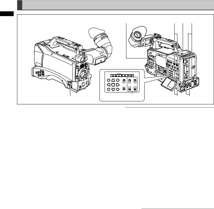
1POWER switch
Use to turn the power on and off.
2Battery holder
A battery from Anton/Bauer is mounted here.
For details, refer to [Mounting the Battery and Setting the Battery Type] (page 86).
3DC IN (external power input) socket (XLR, 4P)
Connect this camera to an external DC power supply. For details, refer to [Use of the external DC power supply] (page 88).
4BREAKER switch
This switch is located on the camera base.
When an excessive amount of current is fed through the video camera recorder, due to a malfunction, the breaker automatically turns off the power to protect the device. Press this button after conducting an internal inspection or repair. The camera will power up if it is working normally.
5Light shoe
A video light or similar accessory can be attached here. (Size of holes for securing screws)
• 1/4-20UNC (6 mm or shorter screws)
6Shoulder strap fittings
The shoulder strap is attached here.
For details, refer to [Attaching the Shoulder Strap] (page 97).
7Lens mount (1/3-bayonet mount)
The lens is attached here.
For details, refer to [Mounting the Lens] (page 89).
8Lens lever
Tighten this lever to lock the lens to the lens mount. For details, refer to [Mounting the Lens] (page 89).
9Mount cap
To remove the cap, raise the lens lever. Replace the cap when a lens is not mounted.
10Lens cable/microphone cable clamp
This clamp secures the lens and microphone cables. For details, refer to [Mounting the Lens] (page 89).
11Tripod mount
To mount the camera on a tripod, attach the optional tripod adapter (SHAN-TM700) here.
For details, refer to [Mounting the Camera on a Tripod] (page 97).
12Lens jack (12-pin)
The lens connection cord is connected here. For a detailed description of your lens, refer to the manufacturer’s instruction manual.
13Battery release lever
Pull down the release lever to release the battery.
14Viewfinder left-right positioning ring
For details, see [Adjusting Right and Left Viewfinder Position] (page 78).
15Light control switch
For details, refer to [Power Supply] (page 86).
16Cable holder
Used to secure the light and microphone cables.
17Accessory mounting hole
Accessories can be attached here. Do not use this hole for purposes other than attaching accessories.
(Size of holes for securing screws)
•1/4-20UNC (10 mm or shorter screws)
•3/8-16UNC (10 mm or shorter screws)
Parts andapterCFunctionseirh 2
15
Audio (input) Function Section
2 |
|
|
|
7 |
2 |
8 |
6 |
andCapterFunctionseirh |
|
|
|
Parts |
|
|
|
1 |
4 |
3 |
5 |
|
1MIC IN (microphone input) jack (XLR, 3-pin)
•Connect a microphone (optional accessory) to this jack.
•A phantom-powered microphone may be connected.
To use a phantom-powered microphone, set the menu option F.MIC POWER to ON in the AUDIO SETUP screen.
For details, refer to [Preparing for Audio Input] (page 95).
2AUDIO LEVEL CH1/CH2 (audio channel 1/2 recording level adjustment) controls
•With the AUDIO SELECT CH1/CH2 switch positioned to MAN, these controls can be used to adjust the recording levels for audio channels 1 and 2.
•Note that the controls are designed to be locked. For adjustment, each control must be depressed while turning.
3AUDIO SELECT CH1/CH2 (audio channel 1/2 automatic/manual level adjustment selector) switch
Use this switch to select recording level control mode for Audio Channels 1 and 2.
AUTO: Recording level automatically controlled. MAN: Recording level manually controlled. For details, refer to [Adjusting Recording Levels] (page 54)
4AUDIO IN (audio input selector) switch
Use this switch to select signals recorded through audio channels 1 – 4.
FRONT: Records signals from a microphone connected to the MIC IN jack.
W.L.(WIRELESS):
Records signals from a wireless receiver. REAR: Records signals from audio devices or
microphones connected to the AUDIO IN CH1/CH2 connectors.
NOTE
To record 2-channel wireless input, switch both CH1 and CH2 to W.L. position and set the menu option WIRELESS TYPE in the AUDIO SETUP screen to DUAL.
5AUDIO IN CH1/CH2 (audio channel 1/2) connectors (XLR, 3-pin)
Audio devices or microphones may be connected here. For details, refer to [When Using Audio Devices]
(page 96).
6LINE/MIC/+48V (line input/mic input/mic input +48V) selector switch
Use to select audio signals input to the AUDIO IN CH1/ CH2 connectors.
LINE: Line input for audio signals input from an
audio device
MIC: Audio signal input from microphone with internal power supply (the camera does not supply power to a phantom microphone).
+ 48V: Audio signal input from a microphone that requires an external power supply (The camera supplies power to a phantom microphone).
NOTE
Power is supplied when the menu option R.MICPOWER in the AUDIO SETUP screen is set to ON.
7FRONT AUDIO LEVEL (audio recording level adjustment) control
•This control adjusts the recording level of audio channels 1 and 2.
•With the AUDIO SELECT CH1/CH2 switch positioned to MAN, this control can be used to adjust the recording levels for audio channels 1 and 2.
•Use the menu options FRONT VR CH1 and FRONT VR CH2 in the AUDIO SETUP screen to select the input connector this control will be used for.
8Wireless slot
A Unislot wireless receiver (optional accessory) may be attached here.
16

Audio (output) Function Section
3 4 1
2 |
5 |
6 |
7 |
1MONITOR SELECT (audio channel) CH1/2, CH3/4 selector switch
Use this switch to select the audio channel whose signals are output to the speaker, earphones or AUDIO OUT connectors.
CH1/2: Signal output of audio channels 1 and 2. CH3/4: Signal output of audio channels 3 and 4. The channel indications of the audio level meters in the viewfinder and on the LCD monitor show the channels selected with this switch.
2MONITOR SELECT (audio selection) CH1/3, ST, CH2/4 selector switch
This switch and the MONITOR SELECT CH1/2, CH3/4 switch select the audio signal output to the speaker, earphones and AUDIO OUT connectors.
MONITOR SELECT |
MONITOR SELECT switch (right) |
|||
switch (left) |
CH1/2 |
CH3/4 |
||
|
CH1/3 |
Audio Channel 1 |
Audio Channel 3 |
|
MONITOR |
|
Stereo signals |
Stereo signals |
|
ST |
from Audio |
from Audio |
||
SELECT |
||||
|
Channels 1 and 2*1 |
Channels 3 and 4*1 |
||
|
|
|||
|
CH2/4 |
Audio Channel 2 |
Audio Channel 4 |
|
*1 MIX in the menu option MONITOR SELECT in the AUDIO SETUP screen allows you to change stereo signals to a mixed signal.
3MONITOR (volume) control
Use to control the alarm sound volume and volume of sound output from the monitor speaker and earphones.
4Speaker
The speaker outputs EE sound during recording and reproduced sound during playback. The speaker emits an alarm sound when the warning lamp and indicator light or blink. EE sound and reproduced sound are not output during alarm sound output.
When earphones are connected to the PHONES connector, the sound from the speaker is automatically muted.
5PHONES (earphones) jack (mini jack)
This connector is designed for audio monitoring (stereo) earphones.
6DC OUT (DC power supply) output socket.
This is a 12 V DC output socket that provides a maximum current of 1.5 A.
NOTE
Be sure to check polarity before connecting an external device as incorrect connection could lead to damage.
7AUDIO OUT connector
•This connector outputs audio signals recorded on audio channels 1/2 and 3/4.
•Use the MONITOR SELECT CH1/2, CH3/4 selector switch to select output signals.
Parts andapterCFunctionseirh 2
17

Parts andapterCFunctionseirh 2
Shooting and Recording/Playback Functions Section
1 9 8
11 |
3 |
4 |
10 |
5 |
6 |
7 |
2 |
Shooting and Recording (camera unit)
1ND FILTER (filter switching) control
Use this control to adjust the amount of light entering the MOS sensor during shooting in strong outdoor lighting.
Control |
Setting |
Description |
|
position |
|||
1 |
CLEAR |
Does not use the ND filter. |
|
2 |
1/4ND |
Reduces the amount of light |
|
entering the MOS sensor to 1/4. |
|||
|
|
||
3 |
1/16ND |
Reduces the amount of light |
|
entering the MOS sensor to 1/16. |
|||
|
|
||
4 |
1/64ND |
Reduces the amount of light |
|
entering the MOS sensor to 1/64. |
|||
|
|
2USER MAIN, USER1 and USER2 buttons
These buttons can be assigned user-selected functions in a setting menu. Each button, when pressed, performs the assigned function.
For details, refer to [Assigning functions to USER buttons] (page 53).
3SHUTTER switch
Use to turn the electronic shutter on and off. OFF: The electronic shutter is off.
ON: The electronic shutter is on.
SEL: Changes the speed of the electronic shutter. This dial switch returns to its original position when released. Each push in the SEL direction changes the shutter speed.
For details, refer to [Setting the Electronic Shutter] (page 51).
4AUTO W/B (white/black) BAL switch
AWB: Automatically adjusts the white balance. Set the WHITE BAL switch on the side to [A] or
[B]and use this switch to adjust the white balance, which takes a few seconds. The adjusted value is stored in memory.
When the WHITE BAL switch is set to PRST and the AUTO W/B BAL switch is set to AWB to indicate the color temperature, pushing the AUTO W/B BAL switch towards AWB a second time allows you to change the preset color temperature.
ABB: Automatically adjusts the black balance. For details, refer to [Adjusting the White Balance and Black Balance] (page 48).
5GAIN selector switch
•This switch adjusts video amplifier gain to suit ambient lighting conditions at the time of shooting.
•Use the menu options LOW GAIN, MID GAIN and HIGH GAIN in the SW MODE screen to set the L/M/H position gain values.
•The factory settings for L, M and H positions are 0 dB, 6 dB and 12 dB, respectively.
18

6OUTPUT/AUTO KNEE selector switch
This switch selects the video signals sent from the camera unit to the memory card recorder unit, viewfinder and video monitor.
CAM. AUTO KNEE ON:
Video being recorded through the camera is output with the Auto knee circuit activated. A DRS (Dynamic Range Stretcher) function can be used instead of the AUTO KNEE function. For details, refer to [DRS (Dynamic Range Stretcher) function] (page 9).
CAM. AUTO KNEE OFF:
Video being recorded through the camera is output with the Auto knee circuit turned off. The KNEE point is locked to the level set in the menu.
BARS: Color bar signals are output with the AUTO KNEE circuit turned off.
NOTE
AUTO KNEE function
Usually, when you shoot people or scenery against a strongly lit background and adjust the level to the subject, the background will be totally whited-out, with buildings and other objects blurred. Use of the AUTO KNEE function in situations like these will reproduce the background clearly.
The AUTO KNEE function is effective when:
•The subject is a person positioned in the shade under a clear sky.
•The subject is a person in a vehicle or building and you also want to capture the background visible through a window.
•The subject is a high-contrast scene.
7WHITE BAL (white balance memory selector) switch
Use to select method of white balance adjustment. PRST: Use PRST when you have no time to adjust
the white balance.
•The factory default setting is 3200 K.
•Use a setting menu or push the AUTO W/B BAL switch towards AWB to display the color temperature. While the color temperature is still indicated, push the AUTO W/B BAL switch once again towards AWB to switch between 3200 K and
5600 K.
A • B: Pushing the AUTO W/B BAL towards AWB will automatically adjust the white balance and save the adjusted value in memory A or memory B.
For details, refer to [Adjusting the White Balance] (page 48).
The setting menu also allows you to assign Auto Tracking White balance (ATW) to B. For details, refer to (page 49).
8DISP/MODE CHK button
•Press this button to turn off the viewfinder and LCD display. (The time code indication stays on.)
•A second press of the button turns the display back on and holding it down displays shooting conditions and functions assigned to USER switches.
•It also serves to turn off the alarm sound.
9SYNCHRO SCAN switch
This function adjusts the synchro scan speed when the SHUTTER switch is set to ON and synchro scan is selected.
Pressing the – switch sets a slower shutter speed and pressing the + switch sets a faster one.
For example, to record a computer screen, make adjustments to minimize horizontal bar noise in the viewfinder.
In VFR (Variable Frame Rate) mode, press the JOG dial button and this switch to change the frame rate.
For details, refer to [2. JOG dial button] in [Menu/ Thumbnail Operation Section] (Page 22).
10ZEBRA (zebra pattern) switch
Use this switch to display a zebra pattern in the viewfinder and on the LCD monitor.
For details, refer to [Zebra pattern display] (page 74).
11Focal plane index ( )
)
This symbol indicates the focal plane of the MOS sensor.
It provides a reference for making accurate focal distance measurements from the subject.
Parts andapterCFunctionseirh 2
19

2 |
20 |
25 24 |
19 |
|
18 |
31 |
12 |
|
|
|
|
|
|
|
|
|
|||
andCapterFunctionseirh |
|
|
|
|
|
|
|
|
|
Parts |
|
|
|
|
|
|
|
|
|
|
|
|
28 |
23 |
21 |
|
30 |
29 |
32 |
|
14 16 15 17 |
27 |
22 26 |
|
|
|
|
|
|
|
13 |
|
|
|
|
|
|
|
|
Shooting and Recording/Playback Function Section (Recorder Unit)
12REC button
Press this button to start recording and press once again to stop it.
This button operates in the same way as the VTR button on the lens.
13SDI OUT CHARACTER switch
Use this switch to control the superimposition of character data onto SDI OUT to indicate status or setting menus.
ON: Superimposes characters.
OFF: Does not superimpose characters.
NOTE
In addition to SDI OUT, a setting menu allows you to superimpose characters on VIDEO OUT video.
14 T REW (rewind) button
In stop mode, press this button for fast-reverse playback.
During playback, press this button for fast-reverse playback at about 4x normal speed.
If this button is pressed when playback is paused, the beginning of the clip being played is located in pause mode (cue-up mode).
15 Y FF (fast forward) button
In stop mode, press this button for fast playback. During playback, press this button for fast playback at about 4x normal speed.
If this button is pressed when playback is paused, the beginning of the next clip is located in pause mode (cue-up mode).
16 G STOP button
Press this button to stop playback.
Press this button to stop interval recording and one-shot recording.
17PLAY/PAUSE button
Press this button to view playback in the viewfinder or on a color video monitor.
Press it during playback to pause playback.
18USB 2.0 connector (DEVICE)
19USB 2.0 connector (HOST)
Connect a USB 2.0 cable to this connector.
To enable transfer of data via USB 2.0, set the menu option PC MODE in the SYSTEM SETUP screen to ON. This setting restricts recording, playback and clip operations with the camera. For details, refer to
page 140.
20
20P2 CARD ACCESS LED
This LED indicates the recording and playback status of each card.
For details, refer to [P2 CARD ACCESS LED and status of P2 cards]. (Page 29)
21GENLOCK IN connector
This connector inputs a reference signal when the camera unit is gen-locked, or when the time code is externally locked.
NOTE
•Supply an HD Y signal (1080/59.94i, 720/59.94P) or a composite signal (480/59.94i) as input reference
signal. The subcarrier of VIDEO OUT connector output (composite signal) cannot be externally locked. In SD mode, the signal will not lock to the HD signal.
22REMOTE connector
Some functions can be remote controlled when the remote control unit AJ-RC10G (optional accessory) is connected to the camera.
For details, refer to [Connecting the AJ-RC10G Remote Controller] (page 100).
23VIDEO OUT connector
This connector outputs video signals.
•In HD mode, down-converted composite video signals are output.
•Use the menu option DOWNCON MODE in the OUTPUT SEL screen to set signal output. (The factory setting is LETTER BOX.)
24SD memory card slot
Insert an SD memory card (optional accessory) in this slot. It is used for recording and loading camera setting menus or lens files, uploading meta data and recording proxies (optional).
NOTE
SD memory card precautions
•Use only SD memory cards that conform to the SD standard or the SDHC standard in this camera.
•MultiMediaCards (MMC) cannot be used. (Use of such cards may prevent recording.)
•Be sure to use mini SD card adapters when using mini SD cards with this camera. (Note that this camera will not operate normally when a mini SD adapter is installed without inserting a card. Be sure to insert a card when an adapter is installed.)
•Use of Panasonic SD memory cards and mini SD cards is recommended. Be sure to format such cards in this camera.
•This unit supports the following SD and SDHC memory card capacities.
|
8MB/16MB/32MB/64MB/ |
SD memory cards |
128MB/256MB/512MB/1GB/ |
|
2GB |
SDHC memory |
4GB/6GB/8GB/12GB/16GB/ |
cards |
32GB |
For proxy (optional) recording, use 256 MB, 512 MB, 1 GB, 2 GB SD memory cards labeled “High Speed” or SDHC memory cards.
•For the latest information not available in the Operating Instructions, visit the P2 Support Sites at the following Web site.
https://eww.pavc.panasonic.co.jp/pro-av
About SD and SDHC memory cards
•The SDHC card is a new standard, established by the SD Card Association in 2006, for memory cards with capacities of 2 GB or more.
•The SD logo is a registered trademark.
•MMC (MultiMediaCard) is a registered trademark of Infineon Technologies AG.
25BUSY (operation mode display) lamp
This lamp indicates the active status of the SD memory card. It stays illuminated when the card is active.
NOTE
Do not remove the card while the lamp is on. The SD memory card could be damaged.
26DVCPRO/DV connector
An IEEE1394 standard connector for input and output of video, audio and data.
For details, refer to [Connections to the DVCPRO/DV Connector] (page 145).
27SDI OUT 1 connector
28SDI OUT 2 connector
•This connector outputs SDI signals.
•Use the menu option SDI SELECT in the OUTPUT SEL screen to select AUTO, 1080i or 480i. This connector does not support up-conversion.
It outputs the same signals as SDI OUT 1 connector.
29SCENE FILE dial
This dial allows you to select and load shooting conditions from the scene files prerecorded to each of the six positions.
NOTE
During recording, selecting a position with a different frame rate will not change the frame rate until the camera is set to recording standby mode.
For details, refer to [How to use Scene File Data] (page 82).
30FOCUS ASSIST button
Turns magnification of the center portion of the image on and off.
For details, refer to [Focus assist function] (page 75).
31REC switch
Switches functions of the REC button on the handle. ON: Enables the REC button.
OFF: Disables the REC button.
32USB lamp
This lamp lights when the camera is in USB mode (PC mode).
Parts andapterCFunctionseirh 2
21

Parts andapterCFunctionseirh 2
Menu/Thumbnail Operation Section
3 7
6 5 4
2 1
1MENU button
•Hold down the button to open a setting menu screen. A second press of the button returns the previous image.
•This function is not available in the thumbnail display and during recording.
2JOG dial button
•Use this button to go between setting menus and to select and set items in open setting menus.
•In a setting menu, turning the JOG dial button downwards moves the menu cursor downwards and turning it upwards moves the menu cursor upwards. Press the JOG dial button to confirm made settings. For more information, see [Using the menus]
(page 120).
•In VFR (Variable Frame Rate) mode, press this button and use the SYNCHRO SCAN switch to change frame rates.
NOTE
Use the JOG dial button to go between setting menus and select items.
For details, refer to [Viewfinder and LCD Menus] (page 120).
3Thumbnail button
Press this button to open the thumbnail screen. Note that this switchover cannot be performed during recording or playback.
4Thumbnail menu button
In thumbnail display mode, use this button to access thumbnail menu functions to delete clips, for example.
NOTE
Use the cursor, SET and EXIT/CANCEL buttons to select thumbnails and access menu functions.
For details, see [Manipulating Clips with Thumbnails] (page 101).
5CURSOR and SET buttons
Use these buttons to manipulate setting menus, the menu bar and thumbnails.
The four triangular buttons are cursor buttons and the square center button is the SET button.
6EXIT/CANCEL button
Press this button to exit an open thumbnail menu or property window to return to the previous image. Pressing this button while holding down the SHIFT button turns it into a cancel function allowing you to cancel clip selections at one time.
7SHIFT button
Use this button together with other buttons.
•Hold down the SHIFT button and press the cursor button ([ ]) in a thumbnail screen to move the pointer to the thumbnail at the beginning or end of a clip.
•Hold down the SHIFT button and press the SET button to select all clips from a previously selected clip to the clip at the cursor location.
•SHIFT button + EXIT/CANCEL button
This button combination operates like the cancel function.
For details, refer to [6. EXIT/CANCEL button]. Operations while the SHIFT button is pressed are shown blow each button.
22
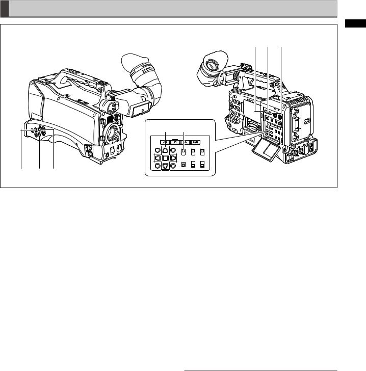
Time Code Section
|
|
|
|
|
2 |
|
|
|
4 |
6 |
5 |
|
|
|
|
|
andFunctionsCaptereirh |
|
|
|
|
|
Parts |
|
|
8 |
7 |
|
|
1 |
3 |
2 |
|
|
|
1GENLOCK IN connector (BNC)
Use this connector to input a reference signal to genlock the camera unit or externally lock the time code. The subcarrier of the VBS signal output by the VIDEO OUT connector of the camera cannot be externally locked.
For details, refer to [Externally Locking the Time Code] (page 62).
2TC IN connector (BNC)
To externally lock the time code, input a reference time code to this connector.
For details, refer to [Externally Locking the Time Code] (page 62).
3TC OUT connector (BNC)
Connect this connector to the time code input (TC IN) of the external device to lock the time code of that device to the time code of the AG-HPX300P.
For details, refer to [Outputting the time code externally] (page 63).
4HOLD button
Pressing this button instantly freezes the time data indication on the counter. Note that time code generation continues. Pressing the button again restarts the counter.
This function allows you to check the time code or counter value of a recorded scene.
5RESET button
Use this button to reset the counter value on the time code display to 0.
Pressing this button with the TCG switch positioned at [SET] when the TC PRESET screen and UB PRESET screen are open, resets all set values to 0. Use the Cursor SET button to PRESET.
6COUNTER (counter display selector) button
Each press of the button displays the counter value, time code, user bit and frame rate data in the viewfinder and LCD display.
7TCG (time code selector) switch
Use this switch to set the running mode of the built-in time code generator.
F-RUN: Select this position to continuously advance the time code independently of P2 card recording status. Use this position to synchronize the time code with the time of day, or to externally lock the time code.
SET: Select this position to set the time code or user bits.
R-RUN: Select this position to advance the time code only during recording. The time code is continuously recorded during normal recording. But deleting clips and setting a 24P/24PA frame rate to continue recording of clips that are not 24P/24PA clips may break the sequence of time code recording.
NOTE
Always use the CURSOR and SET buttons to set the time code and user bits. The JOG dial button cannot be used for this purpose.
8CURSOR and SET buttons
Use these buttons to set the time code and user bits. The four triangular buttons are cursor buttons and the square center button is the SET button.
For details, refer to [Setting Time Data] (page 56).
23

Parts andapterCFunctionseirh 2
Warning and Status Display
Functions
1 |
3 |
4 |
2
1Back tally lamp
When the BACK TALLY switch is set to ON, this lamp behaves in the same way as the front tally lamp.
2Rear tally lamp
When the BACK TALLY switch is set to ON, the rear tally lamp behaves in the same way as the back tally lamp.
3BACK TALLY switch
Use this switch to control the back and rear tally lamps. ON: Enables the back and rear tally lamps. OFF: Disables the back and rear tally lamps.
4WARNING lamp
This lamp starts blinking or lights when an error is detected in the memory card recorder unit.
LCD Monitor
1 |
2 |
1LCD Monitor
The LCD monitor displays the video in the viewfinder. Alternatively, it can show clips on the P2 card in a thumbnail format.
For details on the LCD monitor, refer to [Viewfinder and LCD Menus] (page 120).
In thumbnail display mode, you can use the thumbnail menu buttons, CURSOR and SET buttons to manipulate or delete clips, or format P2 cards.
For details, refer to [Manipulating Clips with Thumbnails] (page 101).
2OPEN button
Use to open the LCD monitor.
24

Viewfnder |
|
|
|
|
2 |
|
|
|
|
|
|
3 |
1 |
5 |
4 |
8 |
7 |
|
|
|
|
|
FunctionsandCaptereirh |
|
|
|
|
|
Parts |
2 |
|
|
|
6 |
|
1Viewfinder
The viewfinder displays the video image in color during recording or playback. It also displays warnings and messages – indicating camera operating status and settings – zebra patterns and markers (safety zone and center markers, etc.).
NOTE
The menu option EVF COLOR can be set to monochrome in the DISPLAY SETUP screen.
2TALLY switch
Use to control the front tally lamp. ON: Tally lamp goes on OFF: Tally lamp goes out.
3Front tally lamp
This lamp goes on during recording when the TALLY switch is set to the [ON] . It blinks to indicate warnings.
4Eyepiece
5Diopter adjusting ring
Adjust this ring to suit your vision so that the image in the viewfinder is as clear as possible.
6Eyepiece lock button
For details, refer to [Detaching the eyepiece] (page 150).
7Microphone holder
8Right and left viewfinder positioning rings
Loosen the rings to adjust right and left position, and tighten the ring after completing the adjustment.
25

Recording ChapterPlaybackand 3
Chapter 3 Recording and Playback
Setting Date and Time of Internal Clock
The CLOCK SETTING value is recorded in the contents (clip), and affects the sequence of playback of the thumbnails. Before carrying out recording, be sure to check and set CLOCK SETTING and TIME ZONE.
This shows you how to adjust the calendar to 5:20 PM on April 1, 2009.
|
|
1 |
Set the POWER switch to ON. |
|
|
2 |
Select TIME ZONE item in OTHER |
|
FUNCTIONS, then press the JOG dial button. |
• For details on menu operation, refer to [Using the menus] (page 120).
3 Use the JOG dial button to set the time difference from Greenwich Mean Time.
•Check what time zone you are in and set accordingly.
OTHER FUNCTIONS
USER FILE |
>>> |
||
1394 |
CONTROL |
OFF |
|
1394 |
CMD SEL |
REC P |
|
ACCESS LED |
ON |
||
ALARM |
HIGH |
||
CLOCK SETTING |
>>> |
||
TIME ZONE |
|
+9:00 |
|
GL PHASE |
|
HD SDI |
|
PUSH MENU TO RETURN
Time zone
Time |
Area |
Time |
Area |
|
difference |
difference |
|||
|
|
|||
00:00 |
Greenwich |
+01:00 |
Central Europe |
|
-00:30 |
|
+01:30 |
|
|
-01:00 |
Azores Islands |
+02:00 |
Eastern |
|
Europe |
||||
|
|
|
||
-01:30 |
|
+02:30 |
|
|
-02:00 |
Mid-Atlantic |
+03:00 |
Moscow |
|
-02:30 |
|
+03:30 |
Tehran |
|
-03:00 |
Buenos Aires |
+04:00 |
Abu Dhabi |
|
-03:30 |
Newfoundland |
+04:30 |
Kabul |
|
Island |
||||
|
|
|
||
-04:00 |
Halifax |
+05:00 |
Islamabad |
|
-04:30 |
|
+05:30 |
Bombay |
|
-05:00 |
New York |
+06:00 |
Dacca |
|
-05:30 |
|
+06:30 |
Yangon |
|
-06:00 |
Chicago |
+07:00 |
Bangkok |
|
-06:30 |
|
+07:30 |
|
|
-07:00 |
Denver |
+08:00 |
Beijing |
|
-07:30 |
|
+08:30 |
|
|
-08:00 |
Los Angeles |
+09:00 |
Tokyo |
|
-08:30 |
|
+09:30 |
Darwin |
|
-09:00 |
Alaska |
+10:00 |
Guam |
|
-09:30 |
Marquesas |
+10:30 |
Lord Howe |
|
Islands |
Island |
|||
|
|
|||
-10:00 |
Hawaii |
+11:00 |
Solomon |
|
Islands |
||||
|
|
|
||
-10:30 |
|
+11:30 |
Norfolk Island |
|
-11:00 |
Midway Island |
+12:00 |
New Zealand |
|
-11:30 |
|
+12:45 |
Chatham |
|
|
Islands |
|||
|
|
|
||
-12:00 |
Kwajalein |
+13:00 |
|
|
+00:30 |
|
|
|
NOTE
•The clock is accurate to within about ±30 seconds a month with the power turned off.
•Check and set the time when accurate time is required. After setting the time, change the setting menu TIME ZONE item and the display and the recorded local time will be reset accordingly.
26

|
|
|
|
|
|
|
|
|
|
|
|
|
4 |
Select CHANGE at the CLOCK SETTING item |
|||||||||||
|
|
in OTHER FUNCTIONS, then press the JOG |
||||||||||
|
|
dial button. |
|
|
|
|
||||||
|
|
• The CLOCK SET screen appears. |
||||||||||
|
|
|
|
|
OTHER FUNCTIONS |
|||||||
|
|
|
USER FILE |
>>> |
|
|||||||
|
|
|
1394 CONTROL |
|
OFF |
|||||||
|
|
|
1394 CMD SEL |
|
REC P |
|||||||
|
|
|
ACCESS LED |
|
ON |
|||||||
|
|
|
ALARM |
|
ON |
|||||||
|
|
|
CLOCK SETTING |
|
|
RETURN |
|
|||||
|
|
|
TIME ZONE |
|
|
CHANGE |
|
|||||
|
|
|
GL PHASE |
|
HD SDI |
|
||||||
|
|
|
|
|
|
|
|
|
|
|
|
|
|
|
|
|
PUSH MENU TO RETURN |
||||||||
|
|
|
|
|
|
|
|
|
|
|
|
|
5 |
Turn the JOG dial button to select YEAR, then |
|||||||||||
|
|
press the JOG dial button. |
||||||||||
|
|
|
|
|
CLOCK SETTING |
|||||||
|
|
|
|
|
|
|
|
2009 |
|
|
||
|
|
|
|
|
YEAR |
|
|
|||||
|
|
|
|
|
MONTH |
APR |
||||||
|
|
|
|
|
DAY |
1 |
|
|
||||
|
|
|
|
|
HOUR |
13 |
|
|
||||
|
|
|
|
|
MINUTE |
7 |
|
|
||||
|
|
|
|
|
|
|
|
|
||||
|
|
|
|
PUSH MENU TO RETURN |
||||||||
|
|
|
|
|
|
|
|
|
|
|
|
|
6 |
Turn the JOG dial button to set YEAR to 2009, |
|||||||||||
|
|
then press the JOG dial button. |
||||||||||
|
|
• A year between 2000 to 2037 can be set. |
||||||||||
|
|
|
|
|
|
|
|
|
|
|
|
|
7 |
Turn the JOG dial button to select MONTH, |
|||||||||||
|
|
then press the JOG dial button. |
||||||||||
|
|
|
|
|
|
|
|
|
|
|
|
|
8 |
Turn the JOG dial button to set MONTH to |
|||||||||||
|
|
APR, then press the JOG dial button. |
||||||||||
|
|
|
|
|
|
|
|
|
|
|
|
|
9 |
Set DAY, HOUR and MINUTE in the same way |
|||||||||||
|
|
as setting YEAR and MONTH. |
||||||||||
|
|
• This is a 24-hour clock. |
|
|
|
|
||||||
|
|
|
|
|
CLOCK SETTING |
|||||||
|
|
|
|
|
YEAR |
2009 |
|
|
||||
|
|
|
|
|
MONTH |
APR |
||||||
|
|
|
|
|
DAY |
1 |
|
|
||||
|
|
|
|
|
HOUR |
17 |
|
|
||||
|
|
|
|
|
MINUTE |
|
20 |
|
|
|||
PUSH MENU TO RETURN
Recording ChapterPlaybackand 3
27
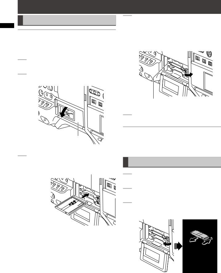
Recording ChapterPlaybackand 3
P2 Cards
Inserting P2 Cards
NOTE
When using the camera recorder for the first time, be sure to set the time data beforehand.
For details, refer to [Setting Date and Time of Internal Clock] (page 26).
1 |
Turn on the POWER switch. |
2 |
Open the card slot cover. |
Slot cover
3 Insert a P2 card in a P2 card slot.
• Press in the card until the eject button pops up.
EJECT button
Insert the card with the logo facing up.
4 Push the eject button that pops up to the right.
• Insert a P2 card into the AG-HPX300P. The P2 CARD ACCESS LED for the appropriate slot indicates the status of the P2 card.
For details, refer to [P2 CARD ACCESS LED and status of P2 cards] (page 29).
P2 CARD ACCESS LED
5 Close the card slot cover.
NOTE
•To prevent cards from falling out, dust from entering and reduce the risk of exposure to static electricity, close the card slot cover before moving the camera.
•Format P2 cards only on a P2 card device.
Removing P2 Cards
1 |
Open the card slot cover. |
2 |
Raise the eject button. |
3 |
Then depress the eject button to release the P2 |
|
card. |
Raise the eject button. |
Press the raised eject |
|
button to remove a P2 |
|
card. |
28

NOTE
•When a P2 card is being accessed or recognised after insertion (P2 CARD ACCESS LED blinks in orange), do not remove the P2 card. Removing a P2 card during access could damage it.
•If a P2 card being accessed is removed, the displays “TURN POWER OFF” and the AGwarning using an alarm and the WARNING all P2 CARD ACCESS LEDs blink rapidly in the case, turn the power off.
For details, refer to [Warning System] (page 151).
•Removing a P2 card during access may corrupt clip data. Check the clips and restore them if required.
For details, refer to [Restoring Clips] (page 109).
•If a P2 card being formatted is removed, it may be not be formatted properly. In this case, the viewfinder displays “TURN POWER OFF”. If this message appears, turn off the power, then restart the AG-HPX300P to reformat the card.
•If a P2 card is inserted while another P2 card is being played back, the inserted P2 card is not recognised and the P2 CARD ACCESS LED for that card does not come on. Card recognition starts when playback ends.
•A P2 card inserted in an empty slot during recording may not be immediately recognized during the following events.
•Immediately following PRE REC operation
•The CARD ACCESS LED can be set to stay off in the menu option ACCESS LED in the OTHER FUNCTIONS screen. When the camera is used in this way, remove cards when the camera has been powered down or a sufficiently long time after terminating recording, playback and other operating modes.
•Removing a P2 card during thumbnail display terminates the thumbnail display.
To Prevent Accidental Erasure of
P2 Card Content
To prevent the content of a P2 card being accidentally erased, position the write-protect switch on the P2 card at [Protect].
Write-protect switch
NOTE
Write-protect switchover can be performed while the card is being accessed (during recording or playback), but does not take effect until access to the card ceases.
P2 |
|
|
MODE |
|
CARD |
|
|
||
Status of P2 Card |
CHECK |
|||
ACCESS |
||||
|
|
indication *1 |
||
LED |
|
|
||
|
|
|
||
Stays on |
Recording |
Writing and |
ACTIVE |
|
in green |
enabled |
reading enabled. |
||
|
||||
|
|
Writing and |
|
|
|
|
reading enabled |
|
|
Stays on |
Selected for |
for current |
|
|
recording mode |
ACTIVE |
|||
in orange |
recording |
|||
(loop, interval |
|
|||
|
|
|
||
|
|
or one-shot |
|
|
|
|
recording). |
|
|
Blinks in |
Being |
Writing or reading |
ACCESSING |
|
orange *2 |
accessed |
being performed. |
||
Quickly |
Being |
The P2 card is |
INFO |
|
blinks in |
||||
recognized |
being recognised. |
READING |
||
orange |
||||
|
|
|
||
|
|
The P2 card has |
|
|
|
Card full |
no free space. |
FULL |
|
|
Only reading is |
|||
|
|
|
||
|
|
enabled. |
|
|
Blinks in |
|
The write-protect |
|
|
green |
|
switch on the P2 |
|
|
|
Write- |
card is positioned |
PROTECTED |
|
|
protected |
at [PROTECT]. |
|
|
|
|
Only reading is |
|
|
|
|
enabled. |
|
|
|
|
The card is not |
|
|
|
Card not |
supported by your |
NOT |
|
|
supported |
AG-HPX300P. |
SUPPORTED |
|
|
|
Replace the card. |
|
|
|
|
The P2 card |
|
|
Stays off |
Incorrect |
is not properly |
FORMAT |
|
format |
formatted. |
ERROR |
||
|
||||
|
|
Reformat the card. |
|
|
|
|
No P2 card is |
|
|
|
Card not |
inserted. |
NO CARD |
|
|
inserted |
Card recognition |
||
|
|
|||
|
|
standby. |
|
|
*1 MODE CHECK appears in the viewfinder and on the LCD monitor.
For details, see [Viewfinder Screen Status Displays] (page 65)
*2 Blinks orange also when a PROXY card (optional accessory) is inserted in slot 2.
3
Recording
29

Recording ChapterPlaybackand 3
P2 card recording times
P2 cards available to the AG-HPX300P
This camera supports the following P2 cards.
•AJ-P2C004HG (4 GB)
•AJ-P2C008HG (8 GB)
•AJ-P2C016AG (16 GB)
•AJ-P2C016RG (16 GB)
•AJ-P2C032AG (32 GB)
•AJ-P2C032RG (32 GB)
•AJ-P2C064AG (64 GB)
NOTE
•Card model numbers and capacities above will become available as of January 2009. Greater capacities and technical innovation may extend the recording time.
•This unit cannot use AJ-P2C002SG (2 GB) cards.
•Use of cards other than those listed above may require updating the camera driver.
For details, refer to [Updating the firmware incorporated into the unit] (page 155).
•For the latest information not available in the Operating Instructions, visit the P2 Support Desk at the following Web site.
https://eww.pavc.panasonic.co.jp/pro-av/
P2 card recording times
(When using one 64 GB card)
System mode |
Recording format |
Recording |
|
(codec) |
time |
||
|
|||
|
AVC-I 100 |
Approx. 64 min. |
|
|
DVCPRO HD |
||
HD (1080i, 720P) |
|
||
AVC-I 50 |
Approx. 128 |
||
|
|||
|
min. |
||
|
|
||
|
DVCPRO50 |
Approx. 128 |
|
|
min. |
||
SD (480i) |
|
||
DVCPRO |
Approx. 256 |
||
|
|||
|
DV |
min. |
NOTE
•The above recording time is for normal recording. Recording in native mode will extend recording time depending on system mode.
For details, refer to [List of recording formats and functions] (page 44).
•Use of 32 GB, 16 GB and 8 GB P2 cards will provide 1/2, 1/4 and 1/8, respectively of above recording times.
•The indicated capacities include a management area so the total area available for recording is somewhat smaller.
Splitting clips recorded on P2 cards
This camera will automatically generate additional clips for a continuous recording on an 8 GB or higher capacity P2 card when the recording exceeds the durations given below. Even so, a P2 device will handle such clips as a
single clip in thumbnail operations (display, delete, recover, copy, etc.). Such recordings may be handled as separate clips by nonlinear editing software or a PC.
Recording format |
Continuous recording time |
|
(excluding Native format) |
||
AVC-I 100 |
Approx. 5 min. |
|
DVCPRO HD |
||
|
||
AVC-I 50 |
Approx. 10 min. |
|
DVCPRO50 |
||
|
||
DVCPRO |
Approx. 20 min. |
|
DV |
||
|
30
 Loading...