


 Loading...
SERVICE INFORMATION
Model No. : AJ-PX270/EJ, AJ-PX285MC,298MC
CONTENTS
1. |
Service Fixture & Tools ................................................................................................................ |
INF-1 |
|
1-1. List of Service Fixture and Tools ........................................................................................... |
INF-1 |
|
1-2. List of Recommended Measuring and Instruments............................................................... |
INF-2 |
2. |
Maintenance................................................................................................................................. |
INF-3 |
|
2-1.Maintenance Schedule ........................................................................................................... |
INF-3 |
|
2-2. Confirmation method of operation number of times of the Zoom Motor ............................... |
INF-3 |
|
2-3. Reset of operation number of times of the Zoom Motor ....................................................... |
INF-3 |
|
2-4. Replacement procedure of Zoom Motor unit......................................................................... |
INF-3 |
3. |
Replacement procedure of Lithium Battery.................................................................................. |
INF-4 |
4. |
Basic Setting Menu Operations.................................................................................................... |
INF-5 |
|
4-1. Construction of Menu ............................................................................................................ |
INF-5 |
|
4-2. Service Menu Operation........................................................................................................ |
INF-5 |
|
4-3. ENG Security......................................................................................................................... |
INF-5 |
5. SERVICE MENU .......................................................................................................................... |
INF-6 |
|
|
5-1. SERVICE MENU screen ....................................................................................................... |
INF-6 |
|
5-2. Making of Service SD memory card...................................................................................... |
INF-9 |
|
5-3. LOG..... .................................................................................................................................. |
INF-9 |
6. |
Software update procedure .......................................................................................................... |
INF-10 |
|
6-1. MICROCOMPUTER / FPGA CHART ................................................................................... |
INF-10 |
|
6-2. Version display method (SERVICE MENU) .......................................................................... |
INF-11 |
|
6-3. Version display method (MAIN MENU) ................................................................................. |
INF-11 |
|
6-4. Update with the SD memory card ......................................................................................... |
INF-12 |
|
6-4-1. Preparation of update ................................................................................................. |
INF-12 |
|
6-4-2. Updated procedure ..................................................................................................... |
INF-13 |
7. PC EVR software ......................................................................................................................... |
INF-16 |
|
7-1. Required tools and equipment for PC EVR software............................................................ |
INF-16 |
|
7-2. Setup……… .......................................................................................................................... |
INF-16 |
|
|
7-2-1. Installation method of USB driver ............................................................................... |
INF-16 |
7-3. Setup of PC EVR software.................................................................................................... |
INF-19 |
|
7-4. |
Function of PC EVR software ............................................................................................... |
INF-20 |
8. Data Backup Procedure............................................................................................................... |
INF-35 |
|
8-1. |
Setup…. ................................................................................................................................ |
INF-35 |
8-2. |
Back Up Procedure ............................................................................................................... |
INF-36 |
|
8-2-1. CAM EEPROM Dump……………………………………………………………………..INF-36 |
|
|
8-2-2. BE Data Backup……………………………………………………………………………INF-37 |
|
8-3. |
Backup Data Writing Procedure ........................................................................................... |
INF-37 |
8-3-1. CAM EEPROM Writing Procedure……………………………………………………….INF-37
8-3-2. BE Data Writing Procedure……………………………………………………………….INF-38
9. White Blemish Compensation...................................................................................................... |
INF-39 |
9-1. Blemish Compensation flow.................................................................................................. |
INF-39 |
9-2. Connection ............................................................................................................................ |
INF-39 |
9-3. Blemish Compensation Procedures ..................................................................................... |
INF-40 |
9-3-1. Blemish confirmation .................................................................................................. |
INF-40 |
9-3-2. Manual compensation procedure ............................................................................... |
INF-41 |
9-4. Remarks................................................................................................................................ |
INF-42 |
9-4-1. Delete registered data one by one ............................................................................. |
INF-42 |
9-4-2. Change Parameter about blemish compensation ...................................................... |
INF-42 |
9-4-3. About the position inhibited to register the compensation data.................................. |
INF-42 |
10. Operation after major part exchanged ....................................................................................... |
INF-43 |
10-1. Operation List .................................................................................................................... |
INF-43 |
10-2. Operation flow chart after replacement of major parts...................................................... |
INF-44 |
10-2-1. MAIN P.C.Board. .................................................................................................. |
INF-44 |
10-2-2. LENS Unit ............................................................................................................. |
INF-47 |
10-2-3. LCD Unit / MONITOR P.C.Board.......................................................................... |
INF-47 |
10-2-4. BATTERY R Unit / BATTERY P.C.Board. ............................................................ |
INF-48 |
10-2-5. GRIP Unit / ZOOM SW P.C.Board. ...................................................................... |
INF-48 |
10-2-6. HANDLE Unit / HANDLE OP P.C.Board. ............................................................. |
INF-48 |
10-2-7. INT MIC................................................................................................................. |
INF-49 |
10-3. Adjustment after replacement of major parts .................................................................... |
INF-50 |
11. P.C.Board Location.................................................................................................................... |
INF-51 |
1. Service Fixture & Tools
1-1. List of Service Fixture and Tools
No. |
NoParts. |
|
Name |
Remarks |
1 |
VVS0114 |
PC EVR Software for AG-PX270 series |
Download from Global Service WEB Site |
|
2 |
VSI5386B |
USB Driver for EVR Adjustment |
Download from Global Service WEB Site |
|
3 |
RFKZ0422 |
Collimator |
*NOTE1: Please refer to the following. |
|
4 |
---------- |
|
Collimator Adaptor |
*NOTE2: Please refer to the following. |
5 |
VFK1642 |
Gray Scale Chart (Reflection type) |
16:9 |
|
6 |
--------- |
|
White chart |
|
7VFK1347 CC Filter (LB120)
8VFK1884 CC Filter (LBA2)
9VFK1888 CC Filter (LBB6)
10 VFK1345 |
CC Filter Holder |
11VFK1346 Step-Down Ring (62mm-52mm)
12VFK1659 Step-Up Ring (43mm-49mm)
13VFK1660 Step-Up Ring (49mm-62mm)
14VFK1809 72mm Attachment Ring
*NOTE1:
The AG-HMC150/HPX170 series is used. Please consult service department of Professional AV Business unit about purchase. It is the same as the service tool used by serving the Digital Still Camera.
*NOTE2:
The AG-HMC150/HPX170 series is used. Please consult service department of Professional AV Business unit about purchase.
INF-1

1 |
VVS0114 |
2 |
VSI5386B |
3 |
RFKZ0422 |
4 |
----- |
PC EVR Software for |
USB Driver |
Collimator |
Collimator Adaptor |
AG-PX270 series |
for EVR Adjustment |
|
|
|
|
DOWN LOAD |
|
|
|
DOWN LOAD |
|
|
|
|
|
|
|
|||
|
|
|
|
|
|
|
|
|
|
|
|
|
|
|
|
|
|
|
|
|
|
|
|
|
|
|
|
|
|
|
|
|
|
5 |
VFK1642 |
6 |
|
|
|
|
|
|
7 |
VFK1347 (LB120) |
10 |
|
VFK1345 |
|||
----- |
|
|
|
|||||||||||||
|
Gray-scale Chart |
|
|
White Chart |
|
8 |
VFK1884 |
(LBA2) |
|
|
CC Filter Holder |
|||||
|
(16:9, Reflection Type) |
|
|
|
|
|
|
|||||||||
|
|
|
|
11 |
VFK1346 |
|||||||||||
|
|
|
|
|
|
|
|
9 |
VFK1888 |
(LBB6) |
||||||
|
|
|
|
|
|
|
|
|
|
|
|
|
Down Ring (62mm - 52mm) |
|||
|
|
|
|
|
|
|
|
|
|
|
|
CC Filter |
|
Step |
||
|
|
|
|
|
|
|
|
|
|
|
|
|
||||
|
|
|
|
|
|
|
|
|
|
|
|
|
|
|
|
|
|
|
|
|
|
|
|
|
|
|
|
|
|
|
|
|
|
VFK1345 VFK1346
12 |
VFK1659 |
14 |
VFK1809 |
Step |
-up Ring (43mm - 49mm) |
|
72 mm Attachment Ring |
13 |
VFK1660 |
|
|
Step |
-up Ring (49mm - 62mm) |
|
|
VFK1659
VFK1660
1-2. List of Recommended Measuring and Instruments
NAME |
REMARKS |
HD Monitor TV |
with SDI input |
Monitor TV |
|
HD/SD Waveform Monitor |
with SDI INPUT |
Vector Scope |
R,G,B/Y,Pb,Pr Display Switching |
Halogen Lamp |
500W 3200K |
Lux Meter |
|
Color Pyrometer |
|
|
|
|
|
INF-2

2. Maintenance
2-1. Maintenance Schedule
No. |
Part Name |
Part No. |
Pcs |
Replacement |
1 |
Zoom Motor Unit |
L6DAYYYC0001 |
1 |
Every 50,000 number of times (SERVO ZOOM) |
|
|
|
|
* Please refer to the following procedures. |
The maintenance execution time shown in the above is recommendation for standard maintenance execution. This is not life of various parts. The life is influenced by temperature, humidity, dust, etc..
2-2. Confirmation method of operation number of times of the Zoom Motor
The operation number of times of Zoom Motor is displayed on item SERVICE INFO in SERVICE menu screen.
1.Confirm that the camera recorder is set to CAMERA mode.
2.Push the button in order of “SHIFT” button → “STOP” button → “Control stick RIGHT”→ “RESET” button → “MENU” button. SERVICE menu (P2 CS SERVICE, DEFECT(SETTING) and DEFECT(EDIT)) will be displayed.
3.Select “P2 CS SERVICE” with Control stick ( ▲ or ▼ direction ) and press SET(Control stick) button.
4.Select “SERVICE INFO” with Control stick ( ▲ or ▼ direction ) and press SET(Control stick) button. SERVICE INFO menu opens.
5.The operation number of times of Zoom Motor is displayed on item SERVO ZOOM in SERVICE INFO menu screen.
OPERATION |
: 474h |
P.ON TIMES |
: 464 |
SERVO ZOOM |
: 800 |
GRIP ZOOM |
: 500 |
HANDLE ZOOM |
: 100 |
LCD OPERATION : 420h
EVF OPERATION : 16h
OK
The operation number of times of the zoom motor of the lens unit is displayed.
NOTE: The display times is updated by every 100 times.
The operation number of times can be confirmed also with the PC EVR software. Please refer to item “5. Hour Meter information” of “7-4. Function of EVR software” about display procedure with PC EVR software.
2-3. Reset of operation number of times of the Zoom Motor
After replacing Zoom Motor unit, set the operation number of times to 0 times.
Please refer to item “6. Hour Meter Reset” of “7-4. Function of EVR software” about setting procedure with PC EVR software.
2-4. Replacement procedure of Zoom Motor unit
The removal procedure has been described to the item “16. Removal of ZOOM MOTOR Unit” of disassembly procedure (SECTION 2).
INF-3

3.Replacement procedure of Lithium Battery
1.Remove the SIDE CASE R S U “VYK6S74”.
2.There is a Lithium battery on the P2 card P.C.B “VEP23724A” (Ref No: ETC100 at foil side of P2 card P.C.B.).
3.Insert the screwdriver to groove of the Lithium Battery Holder and press down it to remove the Lithium Battery. (Pay attention for remove of battery to be pop-up)
4.Install the new battery.
5.Set the date and time of internal clock (Refer to item “Setting the date/time of the internal clock” of operation instructions for the setting method).
NOTE: The date and time of internal clock can be set also with PC EVR software. Please refer to item “<4. Time / Zone setting>” in “7-4. Function of PC EVR Software”.
Insert the screwdriver to remove the Lithium Battery.
Lithium Battery
Type: ML614S
NOTE:
The lithium battery is a critical component.
It must never be subjected to excessive heat of discharge.
It must therefore only be fitted in equipment designed specifically for its use. Replacement batteries must be of the same type and manufacture.
They must be fitted in the same manner and location as the original battery, with the correct polarity contacts observed.
Do not attempt to re-charge the old battery or re-use it for any other purpose.
It should be disposed of in waste products destined for burial rather than incineration.
CAUTION: DANGER OF EXPLOSION IF BATTERY IS INCORRECTLY REPLACED.
REPLACE ONLY WITH THE SAME OR EQUIVALENT TYPE.
INF-4
4. Basic Setting Menu Operations
4-1. Construction of Menu
MENU |
|
|
|
|
Menu Type |
How to open |
|
These menu is mentioned |
|
||||
|
|
|
|
|
User menu |
Press the <MENU> button |
|
in the Operating Instructions. |
|
||||
|
|||||||||||||
|
|
|
|
|
Main menu |
Press and hold the <MENU> |
|
|
|
|
|||
|
|
|
|
|
|
button for 3 seconds or more. |
|
|
|
|
|||
|
|
|
|
|
Option menu |
Press the <MENU> button while |
|
|
|
|
|||
|
|
|
|
|
|
pressing and holding the <LCD |
|
|
|
|
|||
|
|
|
|
|
|
|
|
|
|
||||
|
|
|
|
|
|
BACKLIGHT> button. |
|
|
|
|
|||
|
|
|
|
|
|
|
|
|
|
|
|
|
|
|
|
|
|
|
|
|
|
|
SERVICE MENU |
P2 CS SERVICE |
|||
|
|
|
|
|
|
|
|
|
|
|
|
DEFECT (SETTING) |
|
|
|
|
Please refer to item “5. SERVICE Menu” |
|
|
|
|
|
DEFECT (EDIT) |
||||
|
|
|
about contents of the SERVICE menu. |
|
|
|
|
|
|
|
|||
|
|
|
|
|
|
|
|
|
|
|
|
|
|
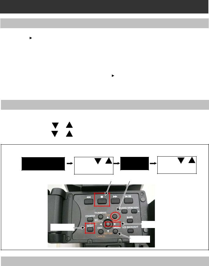
4-2. Service Menu Operation
1.Press <SHIFT> -> <STOP> -> <Control stick RIGHT> -> <RESET> -> <MENU> button in order.
|
SERVICE MENU is displayed. |
|
2. |
Press the Control stick |
or |
|
the selected SUB menu. |
|
3. |
Press the Control stick |
or |
button to open SUB menu function.
to select each Item. And then press “SET(Control stick)” button to open to select the item in SUB menu. And then press “SET(Control stick)”
Press <SHIFT> -> <STOP> -> <Control stick RIGHT> -> <RESET> -> <MENU> button in order. |
|
|||||
SERVICE MENU |
Select with |
or |
SUB MENU |
Select with |
or |
|
Press “SET” button. |
Press “SET” |
button |
||||
|
|
|||||
|
|
|
|
to open the function. |
||
|
|
STOP |
SHIFT |
|
|
|
RESET |
|
|
Control stick |
|
||
|
|
|
|
|
||
|
|
|
MENU |
|
|
|
4-3. ENG Security |
|
|
|
|
|
|
When “ENG SECURITY” in OPTION MENU is set to “ON”, all menus can not be opened except for “USER MENU”. The following procedure allows you to temporarily remove the restriction on displaying menus.
1.Turn the power to “ON” while pressing “AWB” button (on the front) and “REC CHECK” button (on the grip) simultaneously. The restriction is temporarily removed.
2.Open “OPTION MENU” by pressing “MENU” button while pressing “LCD BACKLIGHT” button.
3.Set “ENG SECURITY” to “OFF”.
INF-5

5. SERVICE MENU
The items shown in gray are used in the electrical adjustments.

5-1. SERVICE MENU screen
[ P2CS SERVICE ]
This menu is used for version confirmation or LOG saving.
ITEM |
RANGE & SET VALUE |
PRESET |
Setting contents and outline function explanation |
|
|
VERSION |
|
|
|
|
P2CS BL 1 |
|
|
|
|
P2CS BL 2-1 |
|
|
|
|
P2CS BL 2-2 |
|
|
|
|
P2CS KR |
|
|
|
|
P2CS AP |
|
|
|
|
VUP |
|
All software version is displayed. |
|
VERSION |
VUP FS |
---- |
Pressing right cursor button or left cursor button, next |
|
|
SYSCON |
|
page is displayed. |
|
|
SYS BOOT |
|
|
|
|
SYS FONT |
|
|
|
|
CODEC SOFT |
|
|
|
|
CODEC IPL |
|
|
|
|
AVIO FPGA |
|
|
|
|
CAM EEPROM |
|
|
|
|
|
|
|
|
|
OPERATION |
|
Total operation time (hour meter) |
|
|
P.ON TIMES |
|
The number of times of Power ON |
|
|
SERVO ZOOM |
|
The number of times of Zoom motor (Wide <-> Tele back |
|
|
|
and forward) |
||
SERVICE INFO |
|
|
||
GRIP ZOOM |
|
The number of times of Grip Zoom switch |
||
|
|
|||
|
HANDLE ZOOM |
|
The number of times of Handle Zoom switch |
|
|
LCD OPERATION |
|
LCD operation time (hour meter) |
|
|
EVF OPERATION |
|
EVF operation time (hour meter) |
|
EXTERNAL |
YES / NO |
NO |
This menu is only use at factory. |
|
Please do not execute it. |
||||
|
|
|
||
|
|
|
LOG data can be written on the SD memory card. |
|
|
|
|
MEMORY TO SD: |
|
|
|
|
The LOG data is transfer to SD card from FLASH |
|
|
MEMORY TO SD |
|
ROM (IP3900) on MAIN board (included error log). |
|
LOG* |
--- |
FILE TO SD: |
||
FILE TO SD |
||||
|
|
|||
|
|
|
The LOG data is transfer to SD memory card from |
|
|
|
|
PQ MICON (IC3800) on MAIN board. |
|
|
|
|
* In order to save LOG to SD card, |
|
|
|
|
it is necessary to make a service SD card. |
|
|
P2CS BL 1 |
|
|
|
|
P2CS BL 2-1 |
|
|
|
|
P2CS BL 2-2 |
|
|
|
|
P2CS KR |
|
|
|
|
P2CS AP |
|
The checksum of the each installed software can |
|
MACHINE CHECKSUM |
VUP |
|
||
VUP FS |
|
be confirmed. |
||
|
|
|||
|
SYSCON |
|
|
|
|
SYS BOOT |
|
|
|
|
CODEC SOFT |
|
|
|
|
CODEC IPL |
|
|
|
|
AVIO FPGA |
|
|
INF-6
|
P2CS BL 1 |
|
|
|
P2CS BL 2-1 |
|
|
|
P2CS BL 2-2 |
|
|
|
P2CS KR |
|
|
|
P2CS AP |
|
The checksum of the image data written on the SD |
IMAGE CHECKSUM |
VUP |
|
|
|
memory card can be confirmed. |
||
|
VUP FS |
|
|
|
|
|
|
|
SYSCON |
|
|
|
CODEC SOFT |
|
|
|
CODEC IPL |
|
|
|
AVIO FPGA |
|
|
|
R OFFSET ( 0 – 31 ) |
16 |
|
LCD SUB BRIGHT |
G OFFSET ( 0 – 31 ) |
16 |
|
|
B OFFSET ( 0 – 31 ) |
16 |
|
|
R OFFSET ( 0 – 127 ) |
60 |
|
EVF SUB BRIGHT |
G OFFSET ( 0 – 127 ) |
64 |
|
|
B OFFSET ( 0 – 127 ) |
64 |
|
|
|
|
|
INF-7
[ DEFECT (SETTING) ]
This menu is used for blemish compensation.
ITEM |
RANGE & SET VALUE |
PRESET |
Setting contents and outline function explanation |
|
CONPENSATION |
ON |
ON |
Select the Blemish Compensation ON/OFF. |
|
OFF |
||||
|
|
|
||
MEDIAN FIL |
ON |
ON |
Select the Median Filter ON/OFF. |
|
OFF |
||||
|
|
|
||
USER PICKUP (ABB) |
ON |
ON |
Select function of the automatic blemish compensation. |
|
OFF |
and detection ON/OFF during ABB. |
|||
|
|
|||
USER PICKUP LEVEL |
1-15 |
3 |
Set the detection level of automatic blemish compensation |
|
for USER PICKUP(ABB). |
||||
|
|
|
[ DEFECT (EDIT) ]
This menu is used for blemish compensation.
ITEM |
RANGE & SET VALUE |
PRESET |
Setting contents and outline function explanation |
|
|
|
|
Select EDIT mode or NEW mode. |
|
|
|
|
EDIT: |
|
MODE |
EDIT |
EDIT |
If the current defect data need to change the |
|
NEW |
compensation position, set this mode. |
|||
|
|
|||
|
|
|
NEW: |
|
|
|
|
If new blemish is appeared, set this mode. |
|
|
|
|
Selection of compensation No(000 to 255). |
|
DEFECT NO. |
0 - 255 |
0 |
<NOTE> |
|
|
|
|
Only the EDIT mode is effective. |
|
H CURSOR COARSE |
0-8 |
0 |
Coarse adjustment for horizontal cursor position. |
|
H CURSOR FINE |
0-FF |
00 |
Fine adjustment for horizontal cursor position. |
|
V CURSOR COARSE |
0-4 |
0 |
Coarse adjustment for vertical cursor position. |
|
V CURSOR FINE |
0-FF |
00 |
Fine adjustment for vertical cursor position. |
|
|
|
|
Select the compensation size (Horizontal direction). |
|
|
|
|
1: 1pixel |
|
SIZE |
1,2,3,5,7 |
1 |
2: 2pixel |
|
3: 3pixel |
||||
|
|
|
||
|
|
|
5: 5pixel |
|
|
|
|
7: 7pixel |
|
|
Y |
|
Select the Compensation color. |
|
|
|
Y: R.G.B channel are compensated simultaneously. |
||
|
R |
|
||
COLOR |
Y |
R: R channel is compensated. |
||
G |
||||
|
|
G: G channel is compensated. |
||
|
B |
|
||
|
|
B: B channel is compensated. |
||
|
|
|
||
|
NO INFO |
|
|
|
|
ENTRY |
|
|
|
DEFECT EDIT STATUS |
CHANGE |
OFF |
|
|
DELETE |
|
|||
|
UNABLE |
|
|
|
|
OFF |
|
|
|
ENTRY |
----- |
----- |
Memorize the above data for each DEFECT NO.. |
|
(YES/NO screen appears by selecting this item.) |
||||
|
|
|
||
|
|
|
Each compensation data ( the setting of the parameter |
|
DELETE |
------ |
------ |
with all kinds which is registered on each DEFECT No) |
|
can delete. |
||||
|
|
|
||
|
|
|
(YES/NO screen appears by selecting this item.) |
INF-8
5-2. Making of Service SD memory card
< Method1 >
1.Download the file “Service SD Card (VVS0021.zip)” from Global Service Web Site.
2.Copy the file “Service SD Card (VVS0021.zip)” to hard disk of your PC and extract the file “Service SD Card (VVS0021.zip)”.
3.Insert a formatted SD memory card into the card slot of PC and copy the folder “PRIVATE” to SD memory card.
NOTE: Do not change the construction of folder and file name. The folder construction shown in the following and top of directory should be “PRIVATE”.
Folder: PRIVATE MEIGRO UP PAVCN
 SBG
SBG P2SD MNTNC
< Method2 >
1.Insert a formatted SD memory card into the card slot of PC.
2.Make the following directory and folder.
NOTE: Do not change the construction of folder. The folder construction shown in the following and top of directory should be “PRIVATE”.
Folder: PRIVATE MEIGRO UP PAVCN
 SBG
SBG P2SD MNTNC
SD memory card used in the P2 equipment requires to be conformed to SDTM standards.
Be sure to format SD memory card on this unit.
5-3. LOG
The LOG data can be written on the SD memory card.
Please execute “MEMORY TO SD” and “FILE TO SD”, when you write the LOG data on the SD memory card.
MEMORY TO SD: The LOG data is transfer to SD card from FLASH ROM (IP3900) on MAIN board (included error log).
FILE TO SD: The LOG data is transfer to SD memory card from PQ MICON (IC3800) on MAIN board.
1.Select the item “LOG” on the “P2CS SERVICE” menu and press the SET button.
2.Select the item “MEMORY TO SD” or “FILE TO SD” on the menu and press the SET button. The confirmation menu of the execution is displayed.
3.Select the item “YES” and press SET button, the LOG data is written on the SD memory card.
NOTE: LOG data is saved by following file name to “PRIVATE  MEIGRO UP
 PAVCN SBG P2SD MNT
  NC ” folder
_ERR**.LOG (In case of “MEMORY to SD”) ERR**.LOG (In case of “FILE TO SD”)
INF-9

6. Software update procedure
6-1. MICROCOMPUTER / FPGA CHART
Board |
|
Name |
Ref No. |
IC type |
Remark |
|
|
|
SYSCON* |
|
IP1500 |
MICON |
SYSCAM BOOT : |
|
|
SYS BOOT |
||||
|
|
Besides for update |
||||
|
|
CAM EEPROM |
|
|
||
|
|
|
|
|
||
|
|
SYSCON |
IP1503 |
FLASH |
|
|
|
|
SOFT_EXT |
|
|||
|
|
|
|
|
||
|
|
P2CS BL1 |
|
|
|
|
|
|
P2CS BL2-1 |
|
|
|
|
|
|
P2CS BL2-2 |
IP3900 |
FLASH |
|
|
MAIN |
|
P2CS KR* |
|
|
||
|
|
|
|
|
||
|
P2CS AP* |
|
|
|
P2CS BL1 : Besides for update |
|
|
|
P2CS BOOT |
|
|
||
|
|
|
|
|
||
|
|
VUP* |
|
|
|
|
|
|
VUP FS* |
|
IP3903 |
FLASH |
|
|
|
AVIO FPGA |
|
|
|
|
|
|
|
|
|
|
|
|
|
CODEC SOFT* |
|
IP3501 |
FLASH |
CODEC IPL : Besides for update |
|
|
CODEC IPL |
||||
|
|
|
|
|
||
|
|
|
|
|
||
|
|
|
|
|
||
UP2 CARD |
WR2 SOFT |
IP100 |
FLASH |
Besides for update |
||
|
|
|
|
|
|
|
|
|
|
|
|
|
|
|
|
|
|
|
|
|
The version of all software can be confirmed on P2CS SERVICE -> VERSION in SERVICE MENU.
NOTE:
The version of software with * mark can be confirmed on DIAGNOSTIC -> VERSION in Main menu.
INF-10
6-2. Version display method (SERVICE MENU)
Each software version can be confirmed at item “P2CS SERVICE” -> “VERSION” in SERVICE MENU.
1. |
Open SERVICE MENU by pressing <SHIFT> -> <STOP> -> <Control stick RIGHT> -> <RESET> -> <MENU> |
|
|
button in order. |
|
2. |
Select “P2CS SERVICE” with Control stick |
and then press Control stick . The yellow cursor moves to |
|
SUB menu.. |
|
3.Select “VERSION” with Control stick and pressing the SET button, the all firmware version are displayed.
4.Pressing  or
or  Control stick, each software version is displayed.
VERSION : 8.51-00-F.00
OK |
|
|
|
|
|
|
|
|
|
|
|
|
|
|
|
|
|
|
|
|
|
|
P2CS BL1 |
: 1.00-00-0.00 |
|
SYSCON |
: 1.00-00-0.00 |
|||||
|
P2CS BL 2-1 |
: 1.00-00-0.00 |
|
SYS BOOT |
: 1.00-00-0.00 |
|||||
|
P2CS BL 2-2 |
: 1.00-00-0.00 |
|
SYS FONT |
: 1.00-00-0.00 |
|||||
|
P2CS KR |
: 1.00-00-0.00 |
|
CODEC SOFT |
: 1.00-00-0.00 |
|||||
|
P2CS AP |
: 1.00-00-0.00 |
|
CODEC IPL |
: 1.00-00-0.00 |
|||||
|
VUP |
: 1.00-00-0.00 |
|
AVIO FPGA |
: 1.00-00-0.00 |
|||||
|
VUP FS |
: 1.00-00-0.00 |
|
CAM EEPROM |
: 1.00-00-0.00 |
|||||
|
|
|
|
|
|
|
|
|
|
|
|
|
|
|
OK |
|
|
|
|
OK |
|
|
|
|
|
|
|
|
|
|
|
|
6-3. Version display method (MAIN MENU)
Each software version can be confirmed at item “VERSION” of “DIAGNOSTIC” in Main menu.
1.Press MENU button for 3 seconds or more to display the MAIN MENU.
2. Select “DIAGNOSTIC” with Control stick |
and then press Control stick |
. The yellow cursor moves to |
SUB menu.. |
|
|
3. Select “VERSION” with Control stick and pressing the SET button, the firmware version and the registered
|
information is displayed. |
|
|
|
|
|
|
|
|
|
||||||
4. Pressing |
or |
Control stick, each software version is displayed. |
|
|
|
|||||||||||
|
|
|
|
|
|
|
|
|
|
|
|
|
|
|
|
|
|
|
|
|
|
|
|
|
|
|
|
|
|
|
|
|
|
|
|
VERSION |
|
|
: 8.51-00-F.00 |
|
|
|
|
|
|
|
|
|
||
|
|
MODEL NAME |
: AJ-PX270 |
|
|
|
|
|
|
|
|
|
||||
|
|
SERIAL NO |
: A4TDA0003 |
|
|
|
|
|
|
|
|
|
||||
|
|
MAC ADDRESS |
: 8C:C1:21:EF:D6:1E |
|
|
|
|
|
|
|
||||||
|
|
UID |
|
|
: 00804582 19282004 |
|
|
|
|
|
|
|
||||
|
|
|
|
|
|
|
|
|
|
|
|
|
|
|
|
|
|
|
|
|
|
OK |
|
|
|
|
|
|
|
|
|
|
|
|
|
|
|
|
|
|
|
|
|
|
|
|
|
|
|
|
|
|
|
|
|
|
|
|
|
|
|
|
|
|
|
||
|
|
|
|
|
P2CS KR |
: 1.00-00-0.00 |
|
SYSCON |
: 1.00-00-0.00 |
|
||||||
|
|
|
|
|
P2CS AP |
: 1.00-00-0.00 |
|
CODEC SOFT |
: 1.00-00-0.00 |
|
||||||
|
|
|
|
|
VUP |
: 1.00-00-0.00 |
|
AVIO FPGA |
: 1.00-00-0.00 |
|
||||||
|
|
|
|
|
VUP FS |
: 1.00-00-0.00 |
|
|
|
|
|
|
||||
|
|
|
|
|
|
|
OK |
|
|
|||||||
|
|
|
|
|
|
|
OK |
|
|
|
|
|
|
|
|
|
|
|
|
|
|
|
|
|
|
|
|
|
|
|
|
|
|
|
|
|
|
|
|
|
|
|
|
|
|
|
|
|
|
|
|
|
|
|
|
|
|
|
|
|
|
|
|
|
|
|
|
INF-11

6-4. Update with the SD memory card
CAUTION: Before Updating Software
●Do not power down or pull card while upgrading. If the program quits during loading, the data will be erased or part writing condition and the restart is not made. However software can not be updated, please contact Panasonic Service Engineering.
6-4-1. Preparation of update
< Preparation for SD memory card >
1.One piece of SD memory cards (SD: 64MB to 2GB, SDHC: 4GB to 32GB memory card) is required. Use only SD memory cards that comply with the SD or SDHC specifications.
2.Insert an SD memory card into the card slot of this unit and format it.
NOTE: SD memory card used in this unit requires to be conformed to SDTM standards. Be sure to format SD memory card on this unit.
< Copy of Image data for update >
1.Download Image Data “VSI*****.zip” for the update from “Support Desk” web site.
2.Copy the file “VSI*****.zip” to hard disk of your PC and extract the file.
3.Insert a formatted SD memory card into the card slot of PC.
4.Copy the folder “PRIVATE” to one piece of SD memory cards. The downloaded image data (upgrade file:
VSI*****.img) is included in folder “PRIVATE”.
NOTE: Do not change the construction of folder and file name. The folder construction shown in the following and top of directory should be “PRIVATE”.
Folder: PRIVATE  MEIGROUP
  PAVCN
PAVCN  SBG
SBG  P2SD
P2SD  FW
FW  File Name: VSI*****.img
< External Power >
It is best to power the unit from the external power supply. This will prevent the unit from shutting off during updating.
INF-12
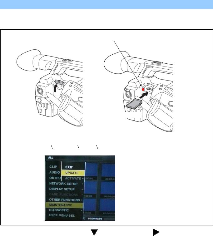
6-4-2. Updated procedure
1.Turn the power on. Press the THUMBNAIL button to thumbnail display screen mode.
2.Insert the SD memory card for update into the SD card slot of this unit.
3.Press the MENU button for 3 seconds or more to display the Main menu on thumbnail screen.
Busy lamp
( SD Access LED)
SD memory card
THUMNAIL -> MAIN MENU -> MAINTENANCE -> UPDATE
4. Select “MAINTENANCE” with Control stick |
and then press Control stick |
. The yellow cursor moves to |
SUB menu.. |
|
|
5.Select “UPDATE” with Control stick and pressing the SET button. (If the update SD memory card does not insert into the unit, item “UPDATE” does not appeared.). The confirmation menu of the execution is displayed. If update is executed, select the item “YES” and press SET button. In this time, BUSY lamp (SD Access LED) is turned off.
6.Update program is started and the message “PREPARING FOR UPDATE” appears on screen. In this timing, it is doing preparation such as the confirmation of the data of the updating. In this time, BUSY lamp (SD Access LED) is turned on.
INF-13
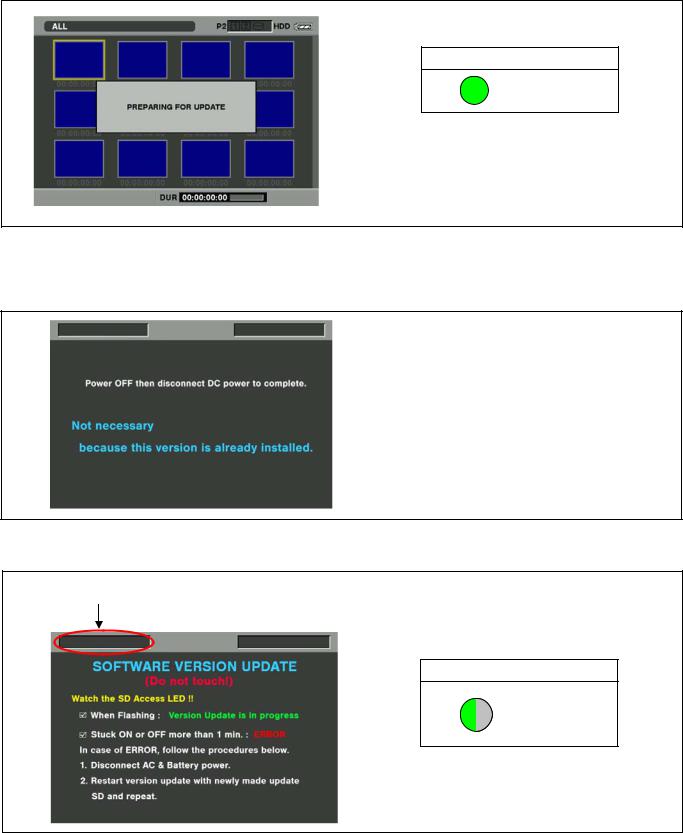
NOTE: To shift to the screen in step 7, it might be necessary for about 60 seconds (Shift time changes with capacity of an image file.).
SD Access LED
ON
NOTE: The following screen is displayed when there is data of the SD memory card in the same version. Please remove the SD memory card and turn the power to OFF (In case of lower version, writing is possible.).
7.When shifting to the update process of the flash and microcomputer, following screen is displayed. During updating software, BUSY lamp (SD Access LED) is blink.
The name of firmware in the update is displayed.
SD Access LED
BLINK
In case that all firmware is updated, it takes approx. 45min (Time changes with capacity of an image file.).
INF-14
Loading...