


Operating Instructions
Camera-Recorder
|
P |
Model No. AJ- |
E |
Before operating this product, please read the instructions carefully and save this manual for future use.
F0706W0 -F @ |
ENGLISH |
|
Printed in Japan VQT0X86
Read this first! (For AJ-HDX900P)
CAUTION |
RISK OF ELECTRIC SHOCK |
DO NOT OPEN |
CAUTION: TO REDUCE THE RISK OF ELECTRIC SHOCK, |
DO NOT REMOVE COVER (OR BACK). |
NO USER SERVICEABLE PARTS INSIDE. |
REFER TO SERVICING TO QUALIFIED SERVICE PERSONNEL. |
The lightning flash with arrowhead symbol, within an equilateral triangle, is intended to alert the user to the presence of uninsulated “dangerous voltage” within the product’s enclosure that may be of sufficient magnitude to constitute a risk of electric shock to persons.
The exclamation point within an equilateral triangle is intended to alert the user to the presence of important operating and maintenance (service) instructions in the literature accompanying the appliance.
WARNING:
OTO REDUCE THE RISK OF FIRE OR SHOCK
HAZARD, DO NOT EXPOSE THIS EQUIPMENT TO RAIN OR MOISTURE.
OTO REDUCE THE RISK OF FIRE OR SHOCK
HAZARD, KEEP THIS EQUIPMENT AWAY FROM ALL LIQUIDS. USE AND STORE ONLY IN LOCATIONS WHICH ARE NOT EXPOSED TO THE RISK OF DRIPPING OR SPLASHING LIQUIDS, AND DO NOT PLACE ANY LIQUID CONTAINERS ON TOP OF THE EQUIPMENT.
CAUTION:
TO REDUCE THE RISK OF FIRE OR SHOCK HAZARD AND ANNOYING INTERFERENCE, USE THE RECOMMENDED ACCESSORIES ONLY.
FCC Note:
This equipment has been tested and found to comply with the limits for a class A digital device, pursuant to Part 15 of the FCC Rules. These limits are designed to provide reasonable protection against harmful interference when the equipment is operated in a commercial environment. This equipment generates, uses, and can radiate radio frequency energy, and if not installed and used in accordance with the instruction manual, may cause harmful interference to radio communications.
Operation of this equipment in a residential area is likely to cause harmful interference in which case the user will be required to correct the interference at his own expense.
Warning:
To assure continued FCC emission limit compliance, the user must use only shielded interface cables when connecting to external units. Also, any unauthorized changes or modifications to this equipment could void the user’s authority to operate it.


 indicates safety information.
A rechargeable battery that is recyclable powers the product you have purchased.
<For USA-California Only>
This product contains a CR Coin Cell Lithium Battery which contains Perchlorate Material – special handling may apply.
See www.dtsc.ca/gov/hazardouswaste.perchlorate.
Caution regarding laser beams
The CCD may be damaged if it is subjected to light from a laser beam.
When using the camera-recorder in locations where laser irradiation equipment is used, be careful not to allow the laser beam to shine directly on the lens.
2

Read this first! (For AJ-HDX900E)
$ DO NOT REMOVE PANEL COVERS BY
UNSCREWING THEM.
To reduce the risk of electric shock, do not remove the covers. No user serviceable parts inside.
Refer servicing to qualified service personnel.
CAUTION:
TO REDUCE THE RISK OF FIRE OR SHOCK HAZARD AND ANNOYING INTERFERENCE, USE THE RECOMMENDED ACCESSORIES ONLY.
WARNING:
OTO REDUCE THE RISK OF FIRE OR SHOCK
HAZARD, DO NOT EXPOSE THIS EQUIPMENT TO RAIN OR MOISTURE.
OTO REDUCE THE RISK OF FIRE OR SHOCK
HAZARD, KEEP THIS EQUIPMENT AWAY FROM ALL LIQUIDS. USE AND STORE ONLY IN LOCATIONS WHICH ARE NOT EXPOSED TO THE RISK OF DRIPPING OR SPLASHING LIQUIDS, AND DO NOT PLACE ANY LIQUID CONTAINERS ON TOP OF THE EQUIPMENT.


 indicates safety information.
Caution regarding laser beams
The CCD may be damaged if it is subjected to light from a laser beam.
When using the camera-recorder in locations where laser irradiation equipment is used, be careful not to allow the laser beam to shine directly on the lens.
3

Read this first! (For AJ-HDX900E)
Attention/Attentie
OBatteries are used for the main power source and memory back-up in the product. At the end of their useful life, you should not throw them away.
Instead, hand them in as small chemical waste.
OVoor de primaire voeding en het reservegeheugen van het apparaat wordt gebruikgemaakt van een batterij.
Wanneer de batterij is uitgeput, mag u deze niet gewoon weggooien, maar dient u deze als klein chemisch afval weg te doen.
To remove the battery/Verwijderen van de batterij
Main Power Battery (Ni-Cd Battery)
Batterij Voor Primaire Voeding (Nikkelcadmiumbatterij)
Anton/Bauer Battery |
Anton/Bauer-Batterij |
Unlock |
Ontgrendelingshefboom |
O If a battery made by any other manufacturer is to be used, check the Operating Instructions accompanying the battery.
O In geval u een batterij van een anden fabrikant zou gebruiken, gelieve dan eerst zorgvuldig de gebruiksaanwijzing van deze batterij te lezen.
Back-up Battery (Lithium Battery)
Batterij Voor Reservegeheugen (Lithiumbatterij)
OFor the removal of the battery for disposal at the end of its service life, please consult your dealer.
ORaadpleeg uw leverancier over de verwijdering van de batterij op het moment dat u het apparaat bij einde levensduur afdankt.
4

Contents
Chapter 1 General ..................................... |
7 |
|
1-1 Features of the camera unit ......................... |
7 |
|
1-2 Features of the VTR unit .............................. |
8 |
|
1-3 |
Features of the Input/Output unit ................ |
8 |
1-4 |
Other featuresa ............................................. |
9 |
1-5 |
Dimensions drawing ..................................... |
9 |
1-6 |
System configuration ................................. |
10 |
Chapter 2 Parts and their functions ...... |
11 |
|
2-1 Power supply and accessory mounting |
|
|
|
section ......................................................... |
11 |
2-2 |
Audio function section ............................... |
12 |
2-3 Shooting and recording/playback function |
||
|
section ......................................................... |
14 |
2-4 |
Menu operation section .............................. |
17 |
2-5 Time code related section .......................... |
18 |
|
2-6 |
Warning/status display section ................. |
19 |
2-7 Display window and its displays ............... |
19 |
|
2-8 |
Viewfinder section ...................................... |
21 |
Chapter 3 Recording and playback ....... |
22 |
|
3-1 |
Cassette tapes ............................................. |
22 |
3-2 |
Basic procedures ........................................ |
23 |
3-3 |
Scene-to-scene continuity ......................... |
25 |
3-4 To record video signals of a few seconds |
|
|
|
before starting recording |
|
|
(PRE-RECORDING function)....................... |
26 |
3-5 Recording in intervals |
|
|
|
(INTERVAL REC function)........................... |
27 |
3-6 To take the previous cut again |
|
|
|
(RETAKE function) ...................................... |
29 |
3-7 To check the last few seconds of the |
|
|
|
recording (Rec-review function) ................ |
29 |
3-8 Normal playback and playback at different |
||
|
speeds .......................................................... |
29 |
Chapter 4 Adjustments and settings for |
|
|
|
recording ................................ |
30 |
4-1 |
Multi Format ................................................ |
30 |
4-1-1 Video system and Recording format ............... |
30 |
|
4-1-2 Recording format on tapes and signal format at |
||
|
output connector ............................................. |
31 |
4-2 Adjusting the white balance and |
|
|
|
black balance .............................................. |
32 |
4-2-1 Adjusting the white balance ............................ |
32 |
|
4-2-2 Adjusting the black balance ............................ |
34 |
|
4-3 Setting the electronic shutter .................... |
35 |
|
4-3-1 Shutter modes ................................................. |
35 |
|
4-3-2 Setting the shutter mode and speed ............... |
36 |
|
4-3-3 Setting the synchro scan mode ....................... |
36 |
|
4-4 Selecting the audio input signals and |
|
|
|
adjusting their recording levels ................. |
37 |
4-4-1 Selecting the audio input signals ..................... |
37 |
|
4-4-2 Adjusting the audio signal recording levels ..... |
37 |
|
4-4-3 CH3 and CH4 recording levels ........................ |
38 |
|
4-5 Setting the time data ................................... |
38 |
|
4-5-1 Setting the user bits ........................................ |
38 |
|
4-5-2 |
Setting the internal clock’s date and time ........ |
42 |
4-5-3 |
Setting the time code ...................................... |
43 |
4-5-4 |
Externally locking the time code ...................... |
43 |
4-5-5 |
Setting the UMID information .......................... |
47 |
4-6 Menu displays on the viewfinder screen ... |
48 |
|
4-6-1 |
Menu configuration .......................................... |
48 |
4-6-2 |
Basic menu operations .................................... |
48 |
4-6-3 |
Selecting the user menus ................................ |
49 |
4-7 Viewfinder screen status displays ............ |
50 |
|
4-7-1 |
Viewfinder lamp displays.................................. |
50 |
4-7-2 Viewfinder screen status display |
|
|
|
configuration..................................................... |
50 |
4-7-3 Selecting the viewfinder screen display |
|
|
|
items ................................................................ |
50 |
4-7-4 Display modes and setting changes/adjustment |
||
|
result messages .............................................. |
56 |
4-7-5 Setting the marker displays ............................. |
56 |
|
4-7-6 |
Setting the camera ID ..................................... |
56 |
4-7-7 |
Mode check screen displays |
|
|
(MODE CHECK button function) ..................... |
57 |
4-7-8 |
Marker check screen displays |
|
|
(MARKER SELECT button function) ............... |
57 |
4-8 Selection of video output signals .............. |
58 |
|
4-8-1 |
Settings of signals output from VIDEO OUT |
|
|
connector ......................................................... |
58 |
4-8-2 |
Settings of signals output from MON OUT |
|
|
connector ........................................................ |
60 |
4-9 Menu-driven function setup ....................... |
61 |
|
4-9-1 |
Setting the USER SW GAIN switching ............ |
61 |
4-9-2 |
Selecting the F.AUDIO LEVEL |
|
|
control function ................................................ |
61 |
4-9-3 |
Allocating functions to the USER MAIN, USER1 |
|
|
and USER2 buttons ........................................ |
62 |
4-9-4 |
Setting the color temperature manually .......... |
63 |
4-10 Set data handling ........................................ |
64 |
|
4-10-1 Handling the setup card .................................. |
65 |
|
4-10-2 |
Setup card operations ..................................... |
65 |
4-10-3 How to use the user data ................................ |
69 |
|
4-10-4 How to use the scene file data ........................ |
70 |
|
4-10-5 Method for returning to user settings .............. |
73 |
|
4-10-6 Method for returning to the factory settings ..... |
73 |
|
4-10-7 |
Lens file ........................................................... |
74 |
4-10-8 |
How to provide lens files ................................. |
74 |
4-10-9 |
To save the lens file into the built-in memory .... |
75 |
4-10-10 To read the lens file from the built-in memory .... |
77 |
|
4-10-11 To write in and read out the lens file to/from the |
||
|
SD memory card ............................................. |
78 |
Chapter 5 Preparation ............................. |
80 |
||
5-1 |
Supplying the power ................................... |
80 |
|
5-1-1 |
Attaching the battery and setting the |
|
|
|
|
battery type ..................................................... |
80 |
5-1-2 |
Use of the external DC power supply .............. |
82 |
|
5-2 |
Attaching the lens and adjusting the flange |
||
|
back .............................................................. |
83 |
|
5-3 |
Adjusting the white shading of the lens ... |
84 |
|
5

Contents (continued)
5-4 |
Audio input signal preparations ................ |
86 |
|
5-4-1 |
When using the front microphone ................... |
86 |
|
5-4-2 |
When using a wireless receiver ...................... |
86 |
|
5-4-3 |
When using an audio component .................... |
87 |
|
5-5 |
Mounting the unit on a tripod .................... |
87 |
|
5-6 |
Attaching the shoulder belt ....................... |
88 |
|
5-7 |
Adjusting the position of the |
|
|
|
shoulder pad ............................................... |
88 |
|
5-8 |
Attaching the rain cover ............................. |
88 |
|
5-9 |
Attacching the FRONT AUDIO LEVEL |
|
|
|
control knob ................................................ |
88 |
|
5-10 |
Connection of the remote control unit |
|
|
|
(AJ-RC10G) .................................................. |
89 |
|
5-11 |
Connection of the external switch ............ |
89 |
|
Chapter 6 Maintenance and |
|
|
|
inspections ............................. |
90 |
6-1 Inspections prior to shooting .................... |
90 |
|
6-1-1 |
Preparation for inspections ............................. |
90 |
6-1-2 Inspecting the camera unit .............................. |
90 |
|
6-1-3 Inspecting the VTR unit ................................... |
91 |
|
6-1-4 |
Self-diagnosis function .................................... |
92 |
6-2 Maintenance ................................................ |
93 |
|
6-2-1 |
Condensation ................................................... |
93 |
6-2-2 |
Head cleaning .................................................. |
93 |
6-2-3 Cleaning inside the viewfinder ........................ |
93 |
|
6-2-4 Phenomena inherent to CCD cameras ........... |
93 |
|
6-2-5 Replacing the backup battery .......................... |
93 |
|
6-2-6 |
Connectors and signals ................................... |
94 |
6-3 Warning system .......................................... |
98 |
|
6-3-1 |
Warning description tables .............................. |
98 |
6-3-2 |
Error codes .................................................... |
100 |
6-3-3 |
Emergency eject ........................................... |
100 |
Chapter 7 Menu description tables ...... |
101 |
||
7-1 |
Menu configfation ..................................... |
101 |
|
7-2 |
SYSTEM SETTING ..................................... |
102 |
|
7-2-1 |
SYSTEM MODE ............................................ |
102 |
|
7-2-2 |
REC FUNCTION ........................................... |
102 |
|
7-2-3 |
OUTPUT SEL ................................................ |
103 |
|
7-2-4 |
VIDEO OUT SETTING .................................. |
103 |
|
7-2-5 |
MONITOR OUT SETTING ............................ |
104 |
|
7-2-6 |
RC OUT SETTING ........................................ |
104 |
|
7-2-7 |
DOWNCON SETTING .................................. |
105 |
|
7-2-8 |
GENLOCK ..................................................... |
105 |
|
7-2-9 |
OPTION MODE ............................................. |
106 |
|
7-3 |
PAINT ......................................................... |
107 |
|
7-3-1 |
RB GAIN CONTROL ..................................... |
107 |
|
7-3-2 |
RGB BLACK CONTROL ............................... |
107 |
|
7-3-3 |
MATRIX ......................................................... |
108 |
|
7-3-4 |
COLOR CORRECTION ................................ |
108 |
|
7-3-5 |
LOW SETTING ............................................. |
109 |
|
7-3-6 |
MID SETTING ............................................... |
110 |
|
7-3-7 |
HIGH SETTING ............................................. |
110 |
|
7-3-8 |
ADDTIONAL DTL .......................................... |
111 |
|
7-3-9 |
SKIN TONE DTL ........................................... |
112 |
|
7-3-10 |
KNEE/LEVEL ................................................ |
113 |
|
7-3-11 |
GAMMA ......................................................... |
113 |
|
7-3-12 |
CAMERA SETTING ...................................... |
114 |
|
7-4 VF |
............................................................... |
115 |
7-4-1 |
VF DISPLAYS ............................................... |
115 |
7-4-2 |
VF MARKER ................................................. |
116 |
7-4-3 |
VF USER BOX .............................................. |
116 |
7-4-4 |
VF INDICATOR1 ........................................... |
117 |
7-4-5 |
VF INDICATOR2 ........................................... |
117 |
7-4-6 |
MODE CHECK IND ....................................... |
118 |
7-4-7 |
!LED .............................................................. |
118 |
7-5 OPERATION ............................................... |
119 |
|
7-5-1 |
CAMERA ID .................................................. |
119 |
7-5-2 |
SHUTTER SPEED ........................................ |
119 |
7-5-3 |
SHUTTER SELECT ...................................... |
119 |
7-5-4 |
USER SW ..................................................... |
120 |
7-5-5 |
SW MODE ..................................................... |
121 |
7-5-6 |
WHITE BALANCE MODE ............................. |
121 |
7-5-7 |
USER SW GAIN ............................................ |
122 |
7-5-8 |
LENS/IRIS ..................................................... |
122 |
7-6 FILE ............................................................ |
123 |
|
7-6-1 |
CARD READ/WRITE .................................... |
123 |
7-6-2 |
CARD R/W SELECT ..................................... |
123 |
7-6-3 |
LENS FILE .................................................... |
123 |
7-6-4 LENS FILE CARD R/W ................................. |
123 |
|
7-6-5 |
SCENE .......................................................... |
123 |
7-6-6 |
INITIALIZE .................................................... |
124 |
7-7 MAINTENANCE ......................................... |
124 |
|
7-7-1 |
SYSTEM CHECK .......................................... |
124 |
7-7-2 |
DIAGNOSTIC ................................................ |
124 |
7-7-3 |
LENS ADJ ..................................................... |
124 |
7-7-4 |
BLACK SHADING ......................................... |
125 |
7-7-5 |
WHITE SHADING ......................................... |
125 |
7-7-6 |
LENS FILE ADJ ............................................ |
125 |
7-8 VTR MENU ................................................. |
126 |
|
7-8-1 |
VTR FUNCTION ........................................... |
126 |
7-8-2 |
BATTERY/TAPE ........................................... |
126 |
7-8-3 |
BATTERY SETTING1 ................................... |
127 |
7-8-4 |
BATTERY SETTING2 ................................... |
128 |
7-8-5 |
MIC/AUDIO1 ................................................. |
129 |
7-8-6 |
MIC/AUDIO2 ................................................. |
129 |
7-8-7 |
TC/UB ........................................................... |
130 |
7-8-8 |
UMID SET/INFO ........................................... |
131 |
7-8-9 |
VTR DIAG ..................................................... |
131 |
7-9 OPTION MENU............................................ |
131 |
7-9-1 OPTION ........................................................ |
131 |
Chapter 8 Specifications ...................... |
132 |
OUniSlot is a trademark of Ikegami Tsusinki co., Ltd.
O“DOLBY” and the double-D symbol Î are trademarks of Dolby Laboratories Licensing Corporation.
OOther names of companies and products are trademarks or registered trademarks of the respective companies.
6

Chapter 1 General
The AJ-HDX900 is a video camera-recorder that integrates an HD camera part equipped with a progressive scan (full pixel reading) 3-CCD camera unit featuring a 2/3-inch on-chip lens with a VTR that in turn supports the DVCPRO HD EX format. 1 The progressive scan CCD produces high quality pictures with superior image expression.
The unit is both compact and lightweight, with minimal power consumption. Featuring high picture quality and sensitivity, the camera-recorder has excellent mobility and effectively withstands dust, humidity, and moisture. With many other superior functions, the unit is the optimum camera-recorder for production.
1-1 Features of the camera unit
OMulti-format
The unit supports the following video systems by driving the CCD progressively. (Refer to page 30)
Video system |
Recording format |
|
|
|
|
1080-59.94i |
1080-59.94i |
|
|
||
1080-29.97P |
||
|
||
|
|
|
1080-23.98P |
1080-59.94i |
|
|
(2-3 Pull-down) |
|
|
|
|
1080-23.98PA |
1080-59.94i |
|
|
(2-3-3-2 Pull-down) |
|
|
|
|
1080-50i |
1080-50i |
|
|
||
1080-25P |
||
|
||
|
|
|
720-59.94P |
|
|
|
|
|
720-29.97P |
720-59.94P |
|
|
|
|
720-23.98P |
|
|
|
|
|
720-50P |
720-50P |
|
|
||
720-25P |
||
|
||
|
|
O Storage type high-sensitivity function (DS. GAIN)
The unit uses the storage type gain increase function by driving the CCD progressively. With this function, it is possible to obtain brighter pictures without increasing noise under low light conditions.
This is a function that makes it possible to achieve higher sensitivity of up to 20 dB above the regular gain increase. Furthermore, this function can also be used as picture effects.
O 14-bit A/D conversion digital signal processing
Analog video signals are processed into digital data by a 14-bit A/D converter with sampling frequencies of 74 MHz. It is possible to reproduce images that are more finely detailed.
O Film-like Gamma function
The unit employs three types of film-like gamma to easily obtain film tones accumulated through Varicam (AJHDC27 series), so that a wide range of image impressions can be reproduced for production. (Refer to page 113)
O Y-get function
By allocating functions to USER button, it is possible to measure the subject’s video level easily. The lens aperture can be adjusted precisely for appropriate pictures. (Refer to page 62)
O Lens file function
The unit has 8 lens files.
By using an SD memory card, 64 lens files can be stored. (Refer to page 74)
O Data management function
Within the unit, one user data file and four sets of scene file data can be saved.
By using an SD memory card as the setup cart, up to eight sets of setup data can be stored. (Refer to page 64)
O Color bar
The unit employs the SMPTE color bar, ARIB color bar, Split color bar for SNG (Satellite News Gathering) as well as the conventional color bar, which is useful for adjusting the color monitor. (Refer to page 121)
O DRS (Dynamic Range Stretcher) function
The dynamic range can be streched by compressing the video signal level of a part with high brightness where white-color-skipping phenomena occur during ordinary shooting. (Refer to page 62)
7

Chapter 1 General (continued)
1-2 Features of the VTR unit
O DVCPRO HD EX format system
The VTR unit employs the DVCPRO HD EX recording format.
Using the latest compression technology, it achieves two times the economy of the conventional DVCPRO HD format.
O PRE RECORDING function provided as a standard configuration
The VTR unit employs the PRE RECORDING function as the standard configuration.
Pictures and voices of up to 7 seconds prior to pressing the VTR REC button can be recorded. (Refer to page 26)
O Interval REC function and ONE-SHOT Recording function provided as a standard configuration
The VTR unit employs the Interval REC function and the ONE-SHOT Recording function as the standard configuration.
With memory control, this unit makes it possible to record in intervals with a minimum recording time in increments of one frame.
This is particularly useful for shooting science and nature programs.
Furthermore, when the unit is used for one-shot recording, frame-by-frame shooting is easily accomplished.
(Refer to page 27)
O Valid frame information
The VTR unit supports multiple formats.
For low frame rates, valid frame information is recorded in the user bits etc.
When HD SDI signals are output, valid frame information is also output. (Refer to page 39)
O Input signals from four separate audio channels
The unit enables audio input signals from four channels to be selected separately. Further, the level of the signal in each channel can be monitored on the LCD display window. (Refer to page 12)
O Built-in DOLBY NR
The CUE audio recording circuitry contains a DOLBY B noise reduction circuit.
O Unislot wireless receiver
The unit’s construction supports a slot-in wireless receiver, which is available as an optional accessory. (Refer to page 86)
1-3 Features of the Input/Output unit
O DVCPRO (IEEE1394) output provided as a standard configuration
By connecting the non-linear editor to the DVCPRO output connector, it is possible to shoot and edit at the same time to improve mobility.
However, control signals and video/audio signals from devices connected to the DVCPRO connector cannot be received. (Refer to page 16)
O Two-system output of HD SDI signals provided
HD SDI outputs are provided independently for Video output and Monitor output.
Since it is possible to turn ON/OFF characters and markers independently for the respective outputs, it can be used fro video monitoring by video creators or recording on hard disks.
On the HD SDI output, the embedded audio and the time code overlap. (Refer to page 31)
O Down converter output provided as a standard configuration
The video output can be switched between HD SDI signals and down converter output signals (analog composite signals).
It is optimum for confirming shot images on the SD monitor. (Refer to page 31)
O SD SDI output provided as a standard configuration
The video output can be switched between HD SDI signals and down converter output signals (serial digital component signals).
It is optimum for confirming shot images on the SD monitor.
On the SD SDI output, the embedded audio overlap. (Refer to page 31)
O Remote control connector
By connecting the remote control unit (AJ-RC10G), which is available as an optional accessory, the unit can be controlled remotely. (Refer to page 89)
O Confirmation of return video signals
It is possible to confirm the return video signals (analog HD-Y signals) supplied to the GENLOCK IN connector of this unit in the viewfinder to confirm programs.
(Only video signals from the same video system can be confirmed.)
(Refer to page 121)
O DC OUT connector
The DC OUT connector of the unit produces 1.5 A of electrical current.
By connecting an external switch to this connector, it is possible to control REC start/stop.
Since a tally lamp can be used by connecting the LED to this connector, it is useful for shooting video when fixing the camera on a crane. (Refer to page 89)
8
Chapter 1 General (continued)
1-4 Other features
O Single action shoulder pad slide function
1
It is now possible to adjust the position where the unit is optimally balanced for operation using a single-touch action. This means that the operator can easily optimize the unit’s balance when the lens, battery, and other peripheral camera devices have been installed on the unit. (Refer to page 88)
O Viewfinder connection
From the viewfinder connector of the unit, 1080-59.94i or 1080-50i signals are output.
Furthermore, signals are output for switching the frequencies of the connected viewfinder.
Confirm images in multi formats by connecting the viewfinder (AJ-HVF21G), which is available as an optional accessory. (Refer to page 50)
O User button
On the side panel of the unit, three user buttons are available.
For the respective buttons, it is possible to allocate functions that are used frequently. (Refer to page 62)
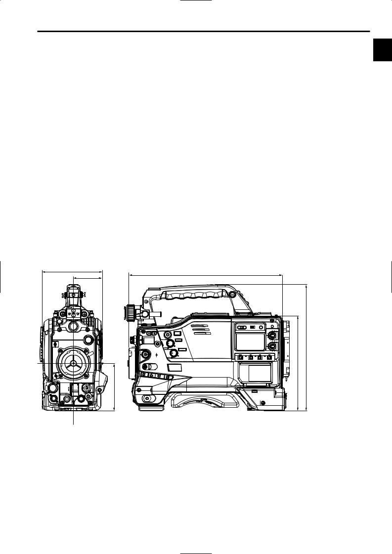
1-5 Dimensions drawing
Unit: mm (inch)
129 (5-1/8) |
329 (13) |
|
62 (2-1/2) |
||
|
102 (4-1/16)
|
16) |
|
11/ |
(8-1/16) |
271 (10- |
204 |
|
9

Chapter 1 General (continued)
1-6 System configuration
Microphone kit:
AJ-MC900G
2-inch electronic HD viewfinder: AJ-HVF21G
(Mic holder provided)
Microphone holder: AJ-MH800G
Lens
(Bayonet type): Fujinon, Canon
GPS unit: AJ-GPS900G
(This unit is not available in European region.)
Rain cover:
SHAN-RC700
Soft carrying case: AJ-SC900
(not available in some area.)
Hard carrying case: AJ-HT901G
UniSlot wireless microphone receiver: Sennheiser EK3041
Camera-Recorder: |
AJ-HDX900 |
Remote control unit:
AJ-RC10G
V-mount type battery plate
NP-1 type battery holder
External DC power supply
Battery
PROPAC14, TRIMPAC14, HYTRON50/100/120, DIONIC90/100/160
ENDURA7/10, BP-GL65/95
NP-L7
SD memory card
Tripod adapter:
SHAN-TM700
Cleaning tape: AJ-CL12MP
M Cassette tapes: AJ-HP23EMG AJ-HP33EMG
<Note>
All of the devices and accessories other than the unit, which are shown in this system configuration, are optionally available. To use these devices and accessories, refer to the respective operation manuals.
10
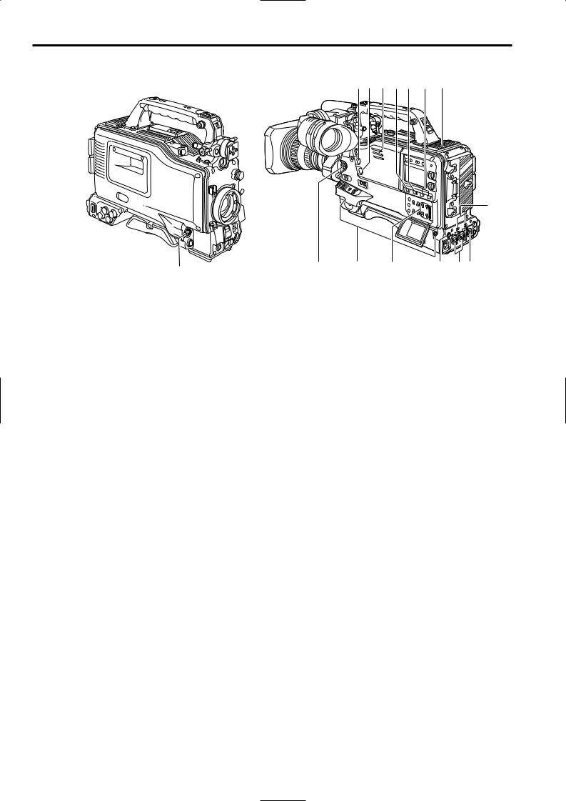
Chapter 2 Parts and their functions
2-1 Power supply and accessory mounting section
6
 2
2
1 |
4 |
3 |
1POWER switch
This switch turns the power ON and OFF.
2Battery mount
This is for attaching the Anton/Bauer battery pack.
3DC IN (external power input) socket (XLR, 4-pin)
This unit is connected to an external DC power supply.
4BREAKER switch
If an excessively high current flows inside the unit due to some problem or other, the circuit breaker is tripped and the power is automatically turned off to protect the unit.
Push this button in after an inspection has been conducted or repairs performed inside the unit by a qualified service person. If there are no problems, the power will come back on.
5VF connector
Viewfinder AJ-HVF21G (optional accessory) is connected here.
Insert the connector for the viewfinder firmly until it clicks.
6Shoulder belt fittings
The shoulder belt is attached here.
7Light shoe
Use this to attach the video light, etc.
8Lens mount (bayonet type)
The lens is attached to this mount.
?7 6
2
5
9
8
 :
:
>= ; <
:Lens mount cap
To remove the cap, push the lens lever 9 up. Keep the cap in place while the lens is not attached.
;Lens cable/microphone cable clamp
This clamp is for anchoring the lens cable or microphone cable.
<Tripod mount
Mount the tripod adapter (SHAN-TM700), available as an optional accessory, when the unit is to be anchored to a tripod.
=LENS jack (12-pin)
The connecting cord of the lens is connected to this jack. For further details on the lenses that can be used, refer to the operating instructions of the lenses concerned.
>Easy-to-adjust shoulder pad
The position of the shoulder pad can be adjusted backward or forward so that the unit is balanced when it is carried on the user’s shoulder.
?GPS connector
GPS unit AJ-GPS900G (optional accessory) is connected here.
(GPS unit AJ-GPS900G is not available in Europe region.)
9Lens lever
This lever is tightened to secure the lens after it has been attached to the lens mount.
11
Chapter 2 Parts and their functions (continued)
2-2 Audio function section (input system)
1
1MIC IN (microphone input) jack (XLR, 5-pin)
Connect the microphone (optional accessory) here. The power for the microphone is supplied from this jack.
<Note>
Components of 150 Hz are removed from the signals input from this connector.
2AUDIO LEVEL CH1/CH2 (audio channel 1 & 2 recording level adjustment) controls
When the AUDIO SELECT CH1/CH2 switch 3 is set to MAN, the recording level of audio channels 1 and 2 can be adjusted using these controls.
The controls come with a locking mechanism. Therefore, to adjust the recording level, simultaneously push in and turn the controls.
3AUDIO SELECT CH1/CH2 (audio channel 1 & 2 automatic/manual level adjustment selector) switch
This is used to select the method for adjusting the recording levels of audio channels 1 and 2.
AUTO : Set here for automatic adjustment.
MAN : Set here for manual adjustment.
4AUDIO IN (audio input selector) switch
These are used to select the input signals to be recorded on audio channels 1 and 2.
FRONT :
The input signals supplied from the microphone which has been connected to the MIC IN jack 1 are recorded.
W.L. (wireless) :
The input signals from the slot-in wireless microphone receiver are recorded.
REAR :
The audio input signals supplied from the audio component which has been connected to the AUDIO IN CH1/CH2 connectors 5 are recorded.
<Note>
When you use stereo microphone (AJ-MC900G optional), set both CH1 and CH2 to [FRONT]. The signal from L CH is recorded to CH1 and that from R CH to CH2.
=< > ; : 3 7
 2
2
6
8 |
? |
4 |
@ 5 9 |
5AUDIO IN CH1/CH2 (audio input channel 1 & 2) connectors (XLR, 3-pin)
An audio component or microphones are connected here. This unit does not support AES/EBU signals.
6LINE/MIC/+48V (line input/mic input/mic input + 48V) selector switch
This is used to switch the audio input signals from the audio component which has been connected to the AUDIO IN CH1/CH2 connectors 5.
LINE : The audio input signals from the audio component serving as the line input are selected.
MIC : The audio input signals from the internal power supply type of microphone are selected. (The phantom mic power is not supplied from the unit.)
+48V : The audio input signals from the external power supply type of microphone are selected. (The phantom mic power is supplied from the unit.)
7Wireless receiver slot
The UniSlot wireless receiver (optional accessory) can be attached here.
8FRONT AUDIO LEVEL (audio recording level adjustment) control
This enables the recording level of audio channels 1 and 2 to be adjusted.
However, when the AUDIO SELECT switch is set to the AUTO position, the audio recording level is automatically adjusted.
When the <MIC/AUDIO1> screen is opened from the VTR MENU page by performing a menu operation, whether to enable or disable the operation of this level control can be set using the FRONT VR CH1 and FRONT VR CH2 setting items.
12

Chapter 2 Parts and their functions (continued)
2-2 Audio function section (output system)
9AUDIO OUT connector (XLR, 5-pin)
The audio signals recorded on audio channels 1 and 2 or audio channels 3 and 4 are output from this connector. The signals to be output can be selected using the MONITOR SELECT CH1/2OCH3/4 selector switch :.
:MONITOR SELECT (audio channel) CH1/2OCH3/4 selector switch
This is used to select the audio channels whose signals are to be output to the speaker, earphone and AUDIO OUT connector.
CH1/2 : The signals of audio channels 1 and 2 are output. CH3/4 : The signals of audio channels 3 and 4 are output. In addition, the channel indications for the audio level meters appearing in the display window and viewfinder change when this switch is operated.
;MONITOR SELECT (audio selection) CH1/3OSTOCH2/4 selector switch
This is linked with the MONITOR SELECT CH1/2OCH3/4 selector switch : and used to select the sound which is to be output from the speaker, earphone and AUDIO OUT connector.
CH1/3 : The signals of audio channel 1 or 3 are output. ST : The stereo audio signals of either audio channels
1 and 2 or audio channels 3 and 4 are output. Using a menu setting, the stereo signals can be changed to MIX signals.
CH2/4 : The signals of audio channel 2 or 4 are output.
MONITOR SELECT CH1/2OCH3/4 selector switch
|
CH1/2 |
CH3/4 |
|
|
|
|
|
CH1/3 |
Audio channel 1 |
Audio channel 3 |
|
|
|
|
|
ST |
Stereo2 signals of audio |
Stereo2 signals of audio |
|
channels 1 and 2 |
channels 3 and 4 |
||
|
|||
|
|
|
|
CH2/4 |
Audio channel 2 |
Audio channel 4 |
|
|
|
|
> Speaker |
|
The EE sound during recording or the playback sound |
2 |
during playback can be monitored through this speaker. |
The warning alarms are output in synchronization with the flashing or lighting of the warning lamps and warning displays.
The sound heard from the speaker is automatically cut off when earphones are connected to the PHONES jack ?.
?PHONES (earphones) jack (mini jack)
This is the earphone (stereo) jack which is used to monitor the audio signals. When earphones are connected, the sound from the speaker is automatically cut off. The sound which is output from the two jacks (front and rear) is the same.
@DC OUT (DC power supply) output connector
This normally serves as the DC 12 V output connector. A current of approximately 1.5 A can be supplied.
It is possible to control REC start/stop by connecting an external switch to this connector.
Since a tally lamp can also be used by connecting an LED to this connector, it is useful for shooting video when fixing the camera on a crane.
For details, see “5-11 Connection of the external switch.”
2Either STEREO or MIX can be selected as the setting for the MONITOR SELECT item by opening the <MIC/AUDIO2> screen from the VTR MENU page by performing a menu operation.
<MONITOR (volume) control
This is used to adjust the volume of the monitor speaker or earphone.
=ALARM (warning alarm volume adjustment)
This is used to adjust the volume of the warning alarms from the earphones which have been connected to the speaker > or PHONES jack ?.
The warning alarms are not audible when this control is at its lowest setting.
13

Chapter 2 Parts and their functions (continued)
2-3 Shooting and recording/playback function section
1 |
4 9 |
8 |
D |
G |
H |
|
|
|
|||
|
|
|
|
6 |
5 |
|
|
|
|
/REW |
FF/ |
|
|
|
EJECT |
STOP |
PLAY/PAUSE |
|
|
|
|
ª |
1/; |
|
|
|
|
E |
F |
: |
|
3 |
|
; |
@ |
|
|
|
A |
2 <567 ? > = |
JBC I |
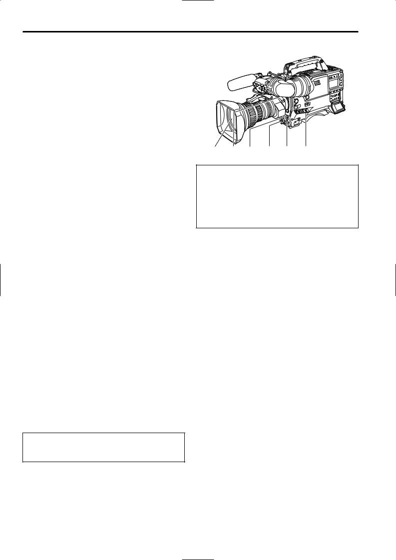
Shooting and recording (camera unit)
1CC FILTER/ND FILTER (filter switching) controls
These are used to select the filter in accordance with the subject’s brightness and color temperature.
CC FILTER knob (outside, large diameter)
A: Cross filter |
B: 3200 K |
|
|
|
C: 4300 K |
D: 6300 K |
|
|
|
ND FILTER knob (inside, small diameter) |
|
|
||
1: CLEAR (transparent) |
2: 1/4 ND |
|
|
|
3: 1/16 ND |
4: 1/64 ND |
|
|
|
∫ Examples of filter selection |
|
|
||
|
|
|
|
|
Shooting conditions |
|
CC filter |
|
ND filter |
|
|
|
|
|
Sunrise, sunset, inside a studio |
|
B (3200 K) |
1 |
(CLEAR) |
|
|
|
|
|
Outdoors under a clear sky |
|
C (4300 K) or |
2 |
(1/4 ND) or |
|
|
D (6300 K) |
3 |
(1/16 ND) |
|
|
|
|
|
Outdoors under cloudy or rainy |
|
D (6300 K) |
1 |
(CLEAR) or |
skies |
|
|
2 |
(1/4 ND) |
|
|
|
|
|
Snowscapes, high mountains, |
|
C (4300 K) or |
3 |
(1/16 ND) or |
seashores or other perfectly clear |
D (6300 K) |
4 |
(1/64 ND) |
|
scenery |
|
|
|
|
|
|
|
|
|
2AUTO W/B (white/black) BAL switch
AWB : The white balance is automatically adjusted. When the WHITE BAL switch on the side panel is set to A or B and then the AUTO W/B BAL switch is operated, the adjustment value is recorded in the memory.
Note that the unit does not operate when the switch is in PRST position.
ABB : The black balance is automatically adjusted.
If the AUTO W/B BAL switch is held down at the ABB position for 8 or more seconds, the black shading is compensated automatically.
For details, refer to “4-2 Adjusting the white balance and black balance.”
<Note>
When white balance or black balance are being automatically adjusted and the switch is pressed again to either the AWB side or to the ABB side, the automatic adjustment for the side pressed will be stopped.
The adjusted value in this case is the value before automatic adjustment was performed.
3 SHUTTER switch
This is the ON/OFF selector switch of the electronic shutter.
OFF : The electronic shutter does not operate. ON : The electronic shutter operates.
SEL : This is used when the electronic shutter speed is to be changed.
The switch is a non-locking type. The shutter speed changes each time it is operated. For further details, refer to “4-3 Setting the electronic shutter.”
4Synchro scan adjustment switches
These switches become effective when the shutter switch 3 is set to ON and SYNCHRO SCAN is selected. They are used to adjust the synchro scan speed.
When the “–” switch is pressed, the shutter speed is reduced; conversely, when the “+” switch is pressed, it is increased.
During personal computer monitor shooting, etc. adjust these switches to the positions where the horizontal bar noise inside the viewfinder is decreased.
5GAIN selector switch
This is used to select the gain of the video amplifier in accordance with the lighting conditions prevailing at the time of the shooting. The gain values for the L, M and H settings are set ahead of time on the setting menu. Their factory settings are 0 dB, 6 dB and 12 dB, respectively.
14

Chapter 2 Parts and their functions (continued)
6OUTPUT/AUTO KNEE selector switch
This switch selects the video signals which are to be output from the camera unit to the VTR unit, viewfinder and/or video monitor.
CAM. AUTO KNEE ON:
The images shot by the camera are output. The AUTO KNEE circuit operates.
CAM. AUTO KNEE OFF:
The images shot by the camera are output. The MANUAL KNEE circuit operates.
BARS:
Color bar signals are output.
The AUTO KNEE circuit does not operate.
AUTO KNEE function
When shooting with the level set to people or scenes against a highbrightness background, the background will be whitened out, and the buildings and scene in the background will be blurred. If the AUTO KNEE function is activated at times like this, the background will be reproduced clearly. This function is effective for shooting in the following situations:
≥When shooting people in the shade under a clear sky
≥When simultaneously shooting people in a car or indoors and the outside scenery through a window
≥When shooting scenes with a strong contrast
7WHITE BAL (white balance memory selector) switch
This is used to select the method used to adjust the white balance.
PRST:
Set the switch to this position at times when, for instance, there is no time to adjust the white balance. The factory setting for the white balance is 3200K, but this can be changed to any other value by a menu setting. For details, refer to “4-9-4 Setting the color temperature manually.”
A or B:
When the AUTO W/B BAL switch 2 is set to AWB, the white balance is automatically adjusted, and the adjusted value is stored in memory A or memory B. For details, refer to “4-2-1 Ajusting the white balance.”
8MODE CHECK button
Each time this button is pressed, one of the four screen pages (STATUS screen display, !LED screen display, FUNCTION screen display and AUDIO screen display) is selected and displayed on the viewfinder to indicate the camera’s settings.
This does not affect the output signals of the camera.
9MARKER SELECT button
This is used to select the marker information displays on the viewfinder screen. Each time it is pressed, the two marker information display screens set by the menu are
switched in the following sequence: A (A marker display) 2 5 B (B marker display) 5 OFF (no marker display) 5 A,
and so on repeatedly. Note that when the power is switched ON, the display on the viewfinder screen immediately before the power was switched OFF will appear.
For details, refer to “4-7-8 Marker check screen displays.”
:USER MAIN, USER 1 and USER 2 buttons
A user setting can be allocated to each of these buttons using the setting menu. When a button is pressed, the user setting mode allocated to it is selected.
When the button is pressed again, the selected mode is released.
For details, refer to “4-8-4 Allocating functions to the USER MAIN, USER1 and USER2 buttons.”
Shooting and recording (VTR unit)
;REC START button
When this is pressed, recording starts; when it is pressed again, recording stops. This button functions in the same way as the lens VTR button.
<VTR SAVE/STBY (tape protection) switch
This is used to select the power supply mode when the VTR has temporarily stopped recording (REC PAUSE mode).
SAVE: This is the tape protection mode. The cylinder is stopped in the half-loading status.
Less power is consumed than at the STBY position, and the operating time provided by the battery is prolonged.
When the switch is set to this position, the SAVE lamp inside the viewfinder lights.
STBY : When the REC START button ; is pressed, recording on tape will start immediately.
<Notes>
O This unit employs the PRE RECORDING function as a standard configuration.
Images will be recorded immediately after pressing the REC START button when this switch is set to either SAVE or STBY.
However, when the switch is set to SAVE position, the length of time for operating the tape travel mechanism after stopping the recording by pressing the REC START button is slightly longer than when the switch is set to STBY position.
O When the prescribed amount of time has elapsed in the STBY mode, the unit is automatically set to the SAVE mode. To return the unit to the STBY mode, set the VTR SAVE/STBY switch to SAVE, and then again to the STBY position.
15

Chapter 2 Parts and their functions (continued)
=VIDEO OUT OUTPUT SEL (output signal selection) switch
This is used to select the signals output from the VIDEO OUT connector.
VTR : In the recording or other EE mode, the camera images are output from the connectors; in the playback mode, it is the VTR’s playback signals which are output.
CAM : The camera images are output at all times. Furthermore, the audio output signals are synchronized with the video signals as well.
For details on the video output, refer to “4-8-1 Settings of signals output from VIDEO OUT connector.”
>VIDEO OUT CHARACTER switch
This is used to control the superimposing of the
characters onto the images which are output from the VIDEO OUT connector.
ON : The characters are superimposed onto the images. OFF : The characters are not superimposed onto the
images.
For details on the character types, refer to “4-8-1 Settings of signals output from VIDEO OUT connector.”
?VIDEO OUT (signal switching) switch
This switch switches the modes of output signals from the VIDEO OUT connector.
HD SDI: To output HD SDI signals
SD SDI: To output the down-converted SD SDI signals VBS: To output the down-converted composite video
signals
@VIDEO OUT connector
This is an output connector for video signals. Video signals linked to the setting of the VIDEO OUT switch (=, >, ?) are output from here.
AREMOTE (remote control) connector
The AJ-RC10G remote control unit (optional accessory) is connected here.
BMON OUT (Monitor) connector
This is the connector for outputting the video signal which is used for monitoring.
HD SDI signals or analog HD Y signals are output from here.
Whether characters are to be superimposed onto the images output from the VIDEO OUT connector can be selected separately using the internal menu.
For details, refer to “4-8-2 Settings for signals output from the MON OUT connector.”
CGENLOCK IN connector
The HD Y reference signal is supplied to this connector when the camera unit is to be gen-locked or the time code is to be externally locked.
Composite video signals may be input as the reference signal instead but, in this case, the H phase cannot be adjusted. Also, it is not possible to externally lock the sub carrier of the unit’s down-converter output (composite video signal).
O Returned video images can be confirmed in the viewfinder screen by entering HD-Y signals.
DEJECT button
This is pressed to insert or eject the cassette.
ESTOP button
This is pressed to stop the tape travel.
FPLAY/PAUSE button
This is pressed to view the playback picture on the viewfinder screen or using a color video monitor. The button’s lamp comes on during playback.
When it is pressed during playback, the unit is set to pause in the playback mode (PLAY PAUSE), and the button’s lamp flashes. If the unit is left in the pause mode for two minutes, it automatically changes to the stop (STOP) mode.
GREW (rewind) button and lamp
When this button is pressed during stop, the tape is reviewed at high speed. Its lamp lights at this time.
When it is pressed during playback or pause, the tape is reviewed at approximately 4 times the normal tape speed. Both the PLAY lamp and REW lamp light at this time.
During the jump operation, the REW lamp flashes.
HFF (fast forward) button and lamp
When this button is pressed during stop, the tape is cued at high speed. Its lamp lights at this time.
When it is pressed during playback or pause, the tape is cued at approximately 4 times the normal tape speed. Both the PLAY lamp and FF lamp light at this time.
IEMERGENCY screw (inside rubber cap)
If the cassette does not eject even when the EJECT button is pressed, use a screwdriver or similar implement to push and turn the EMERGENCY screw at the same time: this will cause the cassette to be ejected.
For details, refer to “6-3-3 Emergency eject.”
16
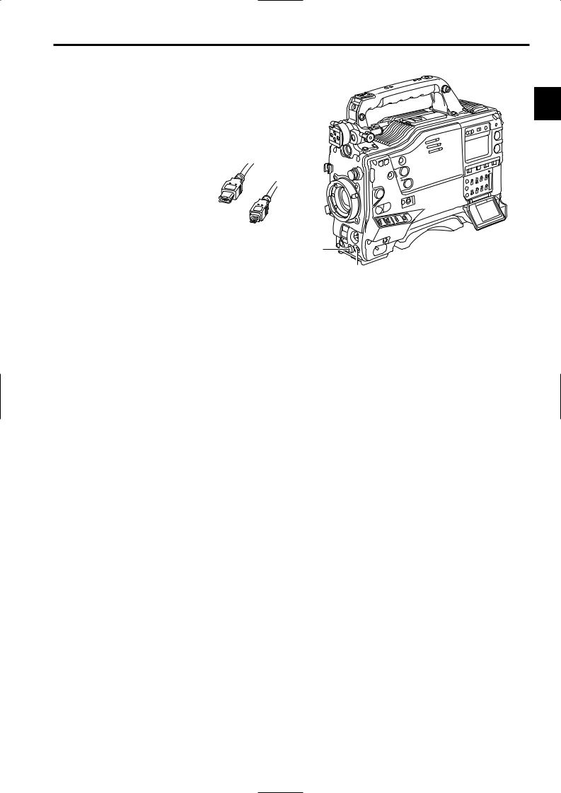
Chapter 2 Parts and their functions (continued)
JDVCPRO connector
This is an output connector for video, voice, and data that comply with the IEEE1394 standard.
<Notes>
O It is impossible to input signals from external devices. O Power is not supplied from the unit.
O Before proceeding to connect or disconnect the DV cable (IEEE1394), be absolutely sure to turn off the power of the units that are to be connected or disconnected using this cable.
O Before proceeding to connect the unit which uses a 6-pin type of DV connector, carefully check the shape of
the connectors on the DV cable and unit. Connecting a connector upside down may damage the parts inside the camera-recorder and cause malfunctioning.
Always connect the DV cable to the unit with the 6-pin type DV connector first.
O You can connect a digital video unit equipped with a DV connector and digitally transfer video and audio signals as well as time codes and other information.
O When a DV cable has been connected to the DV connector, do not apply any strong external force as this may damage the connector.
O To control start/stop of recording operation on the external recording device connected to the DVCPRO connector using the unit, set the 1394 CONTROL item on the menu (OPTION MODE screen on the SYSTEM SETTING page) to “BOTH” (the default setting when shipped from the factory is BOTH).
O When the FireStore FS-100 is used in 1080i mode as an external recording device, set the VITC UB MODE item (TC/UB screen on the VTR MENU page) to “FRM RATE”, so that the frame rates of the unit can be displayed on the display panel of the FS-100.
If it is used in 720P mode, frame rates are not displayed properly but video images will be recorded properly.
2-4 Menu operation section
2
 4
4  3
3
2
1
1MENU button
This is used to switch the menu ON and OFF.
2JOG dial button
This is used to select the menu items and perform settings when the MENU button 1 is at the ON position.
3Setup card insertion slot
This is where the SD memory card (optional accessory) is inserted into the unit.
4BUSY (operation mode display) lamp
This lamp shows the operation mode of the setup card. It lights during operation.
<Note>
When this lamp is lighted, refrain from inserting or removing the card.
17

Chapter 2 Parts and their functions (continued)
2-5 Time code related section
1 3 2
1GENLOCK IN connector (BNC)
The HD Y reference signal is supplied to this connector when the camera unit is to be gen-locked or the time code is to be externally locked. It is also possible to supply composite video signals instead as the reference signal.
2TC IN connector (BNC)
Supply the time code which will serve as the reference to this connector when externally locking the time code.
<Note>
A time code with the same format as the system mode of the unit must be input.
3TC OUT connector (BNC)
To lock the time code of an external VTR to the unit’s time code, connect this connector to the time code input (TC IN) connector on the external VTR.
4HOLD button
The time data display of the counter display section which was on the screen at the moment when this button is pressed is held. (However, the time code generator keeps running.) When the button is pressed again, the hold status is released.
It is used, for instance, to find out the time code or CTL counter value at which a particular scene was shot.
5RESET button
This is used to reset the time data on the counter display section to “00:00:00:00.” If it is pressed while the TCG switch 9 is at the SET position, the time code data and user bits data are respectively reset to “00:00:00:00.”
6DISPLAY switch
This is used to display the time code, CTL or user bits on the counter display section depending on the setting positions of this switch and the TCG switch 9.
UB |
: The user bits are displayed. |
TC |
: The time code is displayed. |
CTL |
: CTL is displayed. |
4 5 6
9
8 7
7“+” button, “–” button
These are used to increment or decrement by 1 the figure in the digit which was made to flash by the SHIFT button 8 when the time code or user bits are to be set.
8SHIFT button
This causes the digit to be set to flash when the time code or user bits are to be set.
9TCG (time code selector) switch
This is used to set the running mode of the built-in time code generator.
F-RUN : Set here to have the time code run all the time regardless of the VTR’s operation.
This position is used to align the time code with
the time or externally lock the time code.
SET : Set here when the time code or user bits are to be set.
R-RUN : Set here to have the time code run only during recording. The time code on the tape with scene-to-scene continuity is recorded continuously.
18
Chapter 2 Parts and their functions (continued)
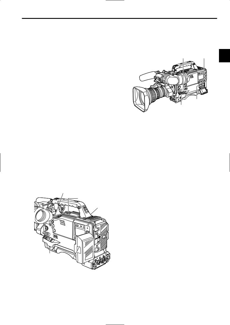
2-6 Warning/status display section
1

 2
2
4
3
5
6
1Back tally lamp
When the back tally switch 2 is set to ON, this lamp serves the same function as the front tally lamp in the viewfinder.
2Back tally switch
This is used to control the unit’s back tally lamp 1 and rear tally lamp 6.
ON : The back tally lamp and rear tally lamp operate. OFF : The back tally lamp and rear tally lamp do not
operate.
3WARNING lamp
When a problem of some form or other occurs within the VTR unit, this lamp flashes or lights.
4LIGHT switch
This controls the lighting of the display window.
Each time it is pressed, the lighting of the display window 5 is set in turn from on to off or vice versa.
5Display window
This displays the alarms, remaining battery charge, audio levels, time data, etc. relating to the VTR unit.
6Rear TALLY lamp
When the back tally switch 2 is set to ON, this lamp operates in exactly the same way as the back tally lamp.
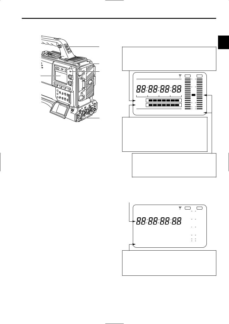
2-7 Display window and its displays
Remaining tape and remaining battery charge and
audio channel level displays
2
Remaining tape display
The remaining tape time is displayed using 7 segments.
The remaining tape time indicated by each segment is set to 3 minutes or 5 minutes using TAPE REMAIN/∫ on the VTR MENU “BATTERY/TAPE” screen. Each time the number of minutes set for the segments elapses, one segment is cleared.
NDF SLAVE HOLD |
|
GPS |
OVER |
OVER |
CTL VTCG TIME DATE P-iREC |
0 |
|
||
|
|
|||
|
|
|
10 |
|
h Y minM |
s D |
frm |
20 |
|
TAPE E |
|
B |
30 |
|
BATT E |
|
F |
|
|
|
40 |
|
||
|
|
|
OO |
|
RF SERVO HUMID SLACK |
13 -dB |
24 |
||
Remaining battery charge display
If a battery with a digital display (% display) is used, all 7 segments up to the “F” position light when the 70% or more of the battery charge remains.
When there is less than 70% of the battery charge remaining, the segments go out one by one in sequence every time the remaining charge drops by 10%. It is also possible to set all 7 segments to light at a 100% battery charge by selecting 100% as the setting for BATT REMAIN FULL on the <BATTERY/TAPE> screen of the VTR menu.
Audio channel level meter
When the MONITOR SELECT CH1/2OCH3/4 switch is set to CH1/2, numbers 1 and 2 indicating the audio channels appear, and the CH1 and CH2 audio levels are displayed. Conversely, when it is set to CH3/4, numbers 3 and 4 indicating the audio channels appear, and the CH3 and CH4 audio levels are displayed.
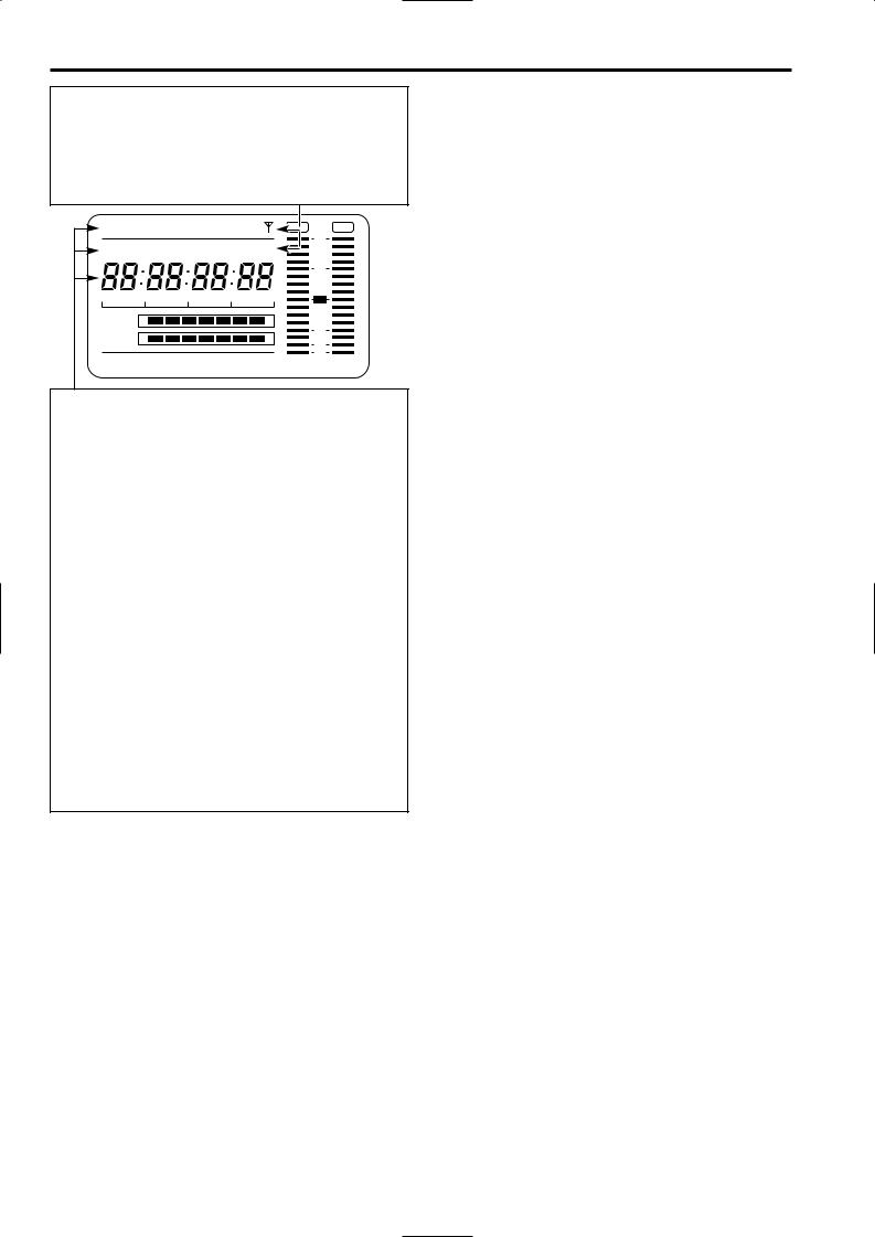
Displays relating to the VTR unit’s operations and modes
Error code display
(for details, refer to “6-3 Warning system”)
NDF SLAVE HOLD |
|
|
|
|
GPS |
OVER |
OVER |
|||||||||||||||||||||
|
|
|
|
|
|
|
|
|
|
|
|
|
|
|
|
|
|
|
|
|
|
|
|
|
0 |
|
|
|
CTL VTCG TIME DATE P-iREC |
|
|
||||||||||||||||||||||||||
|
|
|
|
|
||||||||||||||||||||||||
|
h Y |
|
|
minM |
|
|
|
|
s D |
|
frm |
|
|
|
|
|
|
|||||||||||
|
|
|
|
|
|
|
|
|
|
|
10 |
|
|
|||||||||||||||
|
|
|
|
|
|
|
|
|
|
|
|
|||||||||||||||||
|
|
|
|
|
|
|
|
|
|
|
|
|
|
|
||||||||||||||
|
|
|
|
|
|
|
|
|
|
|
|
|
|
|
||||||||||||||
|
|
|
|
|
|
|
|
|
|
|
|
|
|
|||||||||||||||
|
|
|
|
|
|
|
|
|
|
|
|
|
|
|
||||||||||||||
|
|
|
|
|
|
|
|
|
|
|
20 |
|
|
|||||||||||||||
TAPE |
|
|
|
|
|
|
|
|
|
|
|
|
|
|
|
|
|
|
|
|
|
|
|
|
|
|
|
|
E |
|
|
|
|
|
|
|
|
|
|
|
|
|
|
|
|
B |
|
|
30 |
|
|
||||||
|
|
|
|
|
|
|
|
|
|
|
|
|
|
|
|
|
|
|
|
|
||||||||
BATT |
|
|
|
|
|
|
|
|
|
|
|
|
|
|
|
|
|
|
|
|
|
|
|
|
|
|||
E |
|
|
|
|
|
|
|
|
|
|
|
|
|
|
|
|
F |
|
|
40 |
|
|
||||||
|
|
|
|
|
|
|
|
|
|
|
|
|
|
|
|
|
|
|||||||||||
|
|
|
|
|
|
|
|
|
|
|
|
|
|
|
|
|
|
|
|
|
|
|
|
|||||
|
|
|
|
|
|
|
|
|
|
|
|
|
|
|
|
|
|
|
|
|
|
|
|
|
|
OO |
|
|
RF SERVO HUMID SLACK |
13 -dB |
24 |
||||||||||||||||||||||||||
Warning displays
RF: Clogged video head
SERVO: Servo disturbance
HUMID: Formation of condensation on the head drum
SLACK: Problem in tape take-up
For details, refer to “6-3 Warning system.”
19
Chapter 2 Parts and their functions (continued)
Mode displays
GPS: Lights when signals cannot be received during GPS operation. GPS  : Lights when signals are being received during GPS operation. P-REC: Lights in pre-recording mode and flashes during the time set for
pre-recording after the tally lamp for recording has turned off. iREC: Lights during recording when the interval recording mode is
established; flashes during recording standby.
i:Flashes when the interval recording mode has been selected.
NDF SLAVE HOLD |
|
GPS |
OVER |
CTL VTCG TIME DATE P-iREC |
0 |
||
|
|||
|
|
|
10 |
h Y minM |
s D |
frm |
20 |
TAPE E |
|
B |
30 |
BATT E |
|
F |
|
|
40 |
||
|
|
|
OO |
RF SERVO HUMID SLACK |
13 -dB 24 |
||
Displays relating to the time code
NDF: Lights when the time code is in the non-drop frame mode. DF: Lights when the time code is in the drop frame mode. SLAVE: Lights when the time code is locked externally.
HOLD: Lights when the time generator/reader value is being held. CTL: Lights when CTL is selected by the DISPLAY switch and the
CTL count value is displayed.
TCG: Lights when TC (or UB) is selected by the DISPLAY switch and the TC (or UB) generator value is displayed.
TC: Lights when TC (or UB) is selected by the DISPLAY switch and the TC (or UB) reader value is displayed.
VTCG: Lights when UB is selected by the DISPLAY switch and the VIUB generator value is displayed.
VTC: Lights when UB is selected by the DISPLAY switch and the VIUB reader value is displayed.
TIME: Lights when UB is selected by the DISPLAY switch and the values of the hour, minutes and seconds in real time are displayed.
DATE: Lights when UB is selected by the DISPLAY switch and the values of the year, month and day are displayed in real time.
No display: Remains off when UB is selected by the DISPLAY switch and the real-time values of the hour and minutes in the time zone are displayed.
Time counter display:
The time code, CTL, user bits and real time are displayed.
<Note>
When UB has been selected by the DISPLAY switch, each time the HOLD button is pressed, the setting is switched in the following sequence: VTCG (VTC) 5 DATE 5 TIME 5 no display (time zone) 5 TCG (TC) and so on repeatedly.
Time code-related switch settings and display items
TCG switch position |
DISPLAY switch |
Display item |
|
position |
|||
|
|
||
|
|
|
|
|
TC or CTL |
Time code |
|
SET |
|
|
|
UB |
User bits |
||
|
|||
|
|
|
|
|
CTL |
CTL |
|
F-RUN or R-RUN |
|
|
|
TC |
Time code |
||
|
|
|
|
|
UB |
User bits |
|
|
|
|
20
Chapter 2 Parts and their functions (continued)
2-8 Viewfinder section
= > ; 7 |
9 |
|
:
<
1
|
8 |
ON |
|
|
|
4 5 2 3 6 |
OFF |
|
1Viewfinder (optional accessory)
While recording or playback is underway, pictures can be viewed through the viewfinder in black and white. The warning displays concerning the unit’s operation statuses and settings, messages, zebra patterns and markers (safety zone markers and center marker) can also be seen in the viewfinder.
2ZEBRA (zebra pattern) switch
This is used to display the zebra pattern in the viewfinder.
ON |
: The zebra pattern is displayed. |
OFF |
: The zebra pattern is not displayed. |
3TALLY switch
This is used to control the front tally lamp 7.
HIGH: The brightness of the front tally lamp is increased. OFF : The front tally lamp is turned off.
LOW : The brightness of the front tally lamp is reduced.
4PEAKING control
This is used to enhance the outlines of the images seen inside the viewfinder to make focusing easier. Its adjustment does not affect the output signals of the camera.
5CONTRAST control
This is used to adjust the contrast of the picture seen inside the viewfinder. Its adjustment does not affect the output signals of the camera.
6BRIGHT control
This is used to adjust the brightness of the picture seen inside the viewfinder. Its adjustment does not affect the output signals of the camera.
8Back tally lamp
This lamp lights while the VTR unit is recording. It also flashes to provide a warning display like the REC lamp inside the viewfinder.
When the lever is set to OFF, the back tally lamp is 2 hidden.
9Eyepiece
Do not point the eyepiece at the sun. Doing so may damage the parts inside.
:Diopter adjustment ring
This is adjusted in line with the camera operator’s diopter in such a way that the user can see the image on the viewfinder screen most clearly.
; Connecting plug
< Locking ring
= Microphone holder
>Viewfinder stopper
This is used to attach and remove the viewfinder.
@
?
?Viewfinder left-right position anchoring ring
This is used to adjust the left-right position of the viewfinder.
@Viewfinder front-back position anchoring ring
This is used to adjust the front-back position of the viewfinder.
7 Front tally lamp |
<Note> |
This lamp is activated when the TALLY switch 3 is set to the HIGH or LOW position, and it lights while the VTR unit is recording. It also flashes to provide a warning display like the REC lamp inside the viewfinder. The lamp’s brightness (HIGH or LOW) when it is lighted can be selected using the TALLY switch.
For more information, see the instruction manual for the viewfinder.
21

Chapter 3 Recording and playback
3-1 Cassette tapes
Loading a cassette tape
1 Set the POWER switch to ON.
<Note>
When condensation has formed inside the unit, the HUMID display lights. Wait until this display is cleared before proceeding with the intended operation.
HUMID display
POWER: ON
2 Press the EJECT button. The cassette holder opens.
EJECT button
Cassette holder
Checking for tape slack
Gently push in the reel using your finger and turn the reel in the direction of the arrow. If the reel fails to turn, it means there is no tape slack.
Ejecting the cassette tape
While the power is still on, press the EJECT button to open the cassette holder, and take out the cassette tape. If another cassette is not going to be loaded immediately after this tape is ejected, close the cassette holder.
Ejecting the cassette when the battery has no charge
First, set the POWER switch to OFF to turn off the unit’s power.
Then turn the power back on, and immediately hold down the EJECT button.
The cassette can be removed when there is still some power left in the battery. However, do not repeat this operation.
To prevent accidental erasure
Set the cassette’s tab to SAVE to prevent the recordings on the tape from being erased accidentally.
REC
SAVE
3 Insert the cassette tape and press the part marked with the arrow to close the cassette holder securely.
<Note>
Check that there is no slack in the tape of the cassette.
22
Chapter 3 Recording and playback (continued)
3-2 Basic procedures
This section describes the basic steps for shooting and recording.
Before actually departing to shoot scenes, carry out inspections to ensure that the system is functioning properly.
*For details on how to perform these inspections, refer to “6-1 Inspections prior to shooting.”
From providing the power supply to loading the cassette
1 Attach a fully charged battery pack.
2 Set the POWER switch to ON. Now check that the HUMID display is not showing and that at least 5 segments of the remaining battery charge display are lighted.
≥If the HUMID display is showing, wait until it goes off.
≥When five or more segments of the remaining battery charge display have not lighted, first check the battery setting. If there is nothing wrong with the battery setting, replace the existing battery pack with a fully charged battery pack.
When the MODE CHECK button is pressed to display the status screen in the viewfinder, the type of set battery is shown on the top right of the screen.
3 Check that there are no cables around the cassette holder or top panel, and then press the EJECT button to open the cassette holder.
4 After checking the following points, insert the cassette tape and close the cassette holder.
≥Position of the accidental erasure prevent tab
≥Tape slack
Up to performing the switch settings
Provide the power supply, and load the cassette. Next, set each switch as shown in the figure below, and then proceed to operate.
Switch settings for shooting and recording
|
AUDIO SELECT |
3 |
|
OUTPUT: |
CH 1/CH 2: |
||
CAM/AUTO KNEE ON |
AUTO |
||
|
TCG:
F-RUN or R-RUN
GAIN:
Normally set to 0 dB; change to a more suitable value if the picture is too dark.
MODE CHECK button
3
4
 2
2
2
1
23
Chapter 3 Recording and playback (continued)
Procedure for shooting
From adjusting the white balance and black balance to stopping the recording
1 Select the filter to match the lighting conditions.
2-1 If the white balance has been stored in the memory ahead of time:
Set the WHITE BAL switch to “A” or “B.”
2-2 If the white balance and/or black balance have not been stored in the memory and there is no time to adjust the white balance:
Set the WHITE BAL switch to PRST.
The white balance for the filter is achieved in accordance with the setting position of the CC FILTER control (outer).
2-3 When adjusting the white balance on the spot:
Select the filter to match the lighting conditions, set the WHITE BAL switch to “A” or “B” and adjust the white balance as follows:
1Press the AUTO W/B BAL switch to the AWB position and adjust the white balance.
2Press the AUTO W/B BAL switch to the ABB position and adjust the black balance.
3Press the AUTO W/B BAL switch to the AWB position and adjust the white balance again.
*For details on how to perform the adjustments, refer to “4-2-1 Adjusting the white balance” and “4-2-2 Adjusting the black balance.”
3 Point the camera at the subject, and adjust the focus and zoom.
4 When the electronic shutter is to be used, set the shutter speed and operating mode.
* For further details, refer to “4-3 Setting the electronic shutter.”
5 Press the REC START button or lens VTR button to start recording.
During recording, the REC lamp inside the viewfinder lights.
6 To stop the recording, press the REC START button again.
The REC lamp inside the viewfinder goes off.
Tape function buttons
During recording, the tape function buttons (EJECT, REW, FF, PLAY/PAUSE and STOP) will not work.
From adjusting the white balance and black balance to stopping the recording
3 |
1 4 5, 6 2-3 2-1, 2, 3 |
CAUTION:
The unit records video and audio signals into the built-in memory once, and then reads these signals out and records them on tape. Thus, video images or voice for 2 to 3 seconds will be recorded on tape, when you start recording while the VTR SAVE/STBY switch is set to the SAVE position and then stop it immediately by pressing the REC START button or the VTR button on the lens.
24

Chapter 3 Recording and playback (continued)
3-3 Scene-to-scene continuity
Maintaining continuity from one scene to the next at an accuracy of +1 frame or less can be assured simply by pressing the REC START button or VTR button on the lens while the unit is in the rec-pause mode.
If the unit is in a mode other than rec-pause, the point at which the scene-to-scene continuity is to be maintained must be located before recording is started.
Scene-to-scene continuity during rec-pause
The scene-to-scene continuity timing is located automatically.
≥When the VTR SAVE/STBY switch is set to “SAVE”, the tape loading operation will complete about 2 seconds after pressing the REC START button.
≥When the VTR SAVE/STBY switch is set to “STBY”, the tape loading operation has completed.
≥When recording with the switch set to STBY position, the tape travel mechanism will stop 2 seconds after pressing the REC START button.
When pre-recording is set to 7 seconds, it takes 7 seconds or more to stop the tape travel mechanism after pressing the REC START button.
Ensuring scene-to-scene continuity after the power was turned off while the unit was in the recpause mode
1 Switch the power back on.
2 Press the REC START button or lens VTR button to start the recording.
2 |
1 |
Jump function
To jump to the starting point of the unrecorded section of a tape, open the <SW MODE> screen from the OPERATION page, and set the RET SW item to R. REVIEW.
When the recorded tape is replayed to the starting point of 3 the unrecorded section, the recording head is at Position B.
If the RET button of the lens or the USER button that is allocated the RET SW function is pressed once in this state, the tape will rewind for 5 seconds.
If the recorded section cannot be found, press this button again.
If the recorded section is recognized during the rewind operation, such as Position C, the tape will be rewound for an additional 2 seconds from the termination point A of the recording and then played back for 2 seconds; the tape then pauses the recording at the termination point A.
Press the REC START button or the VTR button of the lens to continue recording from the termination point A.
(In this case, the time code is regenerated as a value for position A on the tape if the TCG switch is set to the R-RUN position.)
When the tape is rewound to the recorded section, the recording head is at Position D. If the RET button of the lens or the USER button that is allocated the RET SW function is pressed once in the STOP mode, the tape rewind for 2 seconds, and then replay for 2 seconds before entering into the pause state for recording at position D.
During the pause in playback, the tape pauses the recording at position D without rewinding or playing back the tape. (In this case, the time code will be regenerated as a value for position D on the tape if the TCG switch is set to the R-RUN position.)
O During the jump operation, the REW lamp flashes and the JUMP indication in the viewfinder screen flashes.
<Notes>
O When the cassette tab is in the “SAVE” position, the jump operation is disabled.
O By executing the jump operation while the TCG switch is set to the R-RUN position, time codes will always be regenerated to the value on the tape.
Even if the TCG switch is set to the SET position or the F- RUN position, the time code will be rewritten to the value on the tape when the jump operation is executed after returning the switch to the R-RUN position. When recording starts, the unit regenerates the time code to the value on the tape. Even if the FIRST REC TC item of the menu (TC/UB screen of the VTR MENU page) is set to PRESET, the time code will always be regenerated to the value on the tape by executing the jump operation after setting the TCG switch to the R-RUN position.
|
2 seconds |
|
|
2 seconds |
|
C |
5 seconds |
|
|
||
D |
A |
|
B |
Recorded |
Unrecorded |
section |
section |
Forward direction of the tape
25
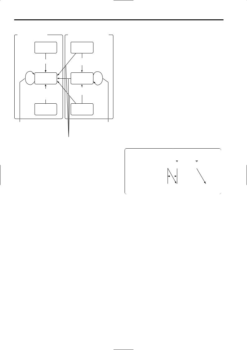
Chapter 3 Recording and playback (continued)
Transitions with the jump operation
Recorded section D |
Section not recorded (B, C) |
Pause for replaying
O Time code regeneration
Pause for recording
O Time code regeneration O Rewound for 2 seconds
and then played back
Pause for replaying
No recorded section is available. O Rewinding for 5 seconds
Pause for recording
No recorded section is available. O Rewinding for 5 seconds
|
Stopped |
|
|
Stopped |
|
|
|
|
|
|
|
Rec-review |
|
No recorded section is available. |
|||
For details, refer to “3-7 To |
|
O Rewinding for 5 seconds |
|||
check the last few seconds of the |
|
|
|
||
recording (Rec-review function)”. |
|
|
|
||
|
|
|
If the recorded section is found |
||
|
|
|
O Rewound to the recorded part |
||
|
|
|
O Time code regeneration |
||
|
|
|
O Rewound for 2 seconds and then |
||
|
|
|
played back |
||
3-4 To record video signals of a few seconds before starting recording (PRE-RECORDING function)
By always storing a few seconds’ worth (maximum of 7 seconds) of audio and video data shot by the camera, it is possible to record video and audio signals a few seconds before recording is actually started by pressing the REC START button or the VTR button on the lens in the built-in memory.
In order for this function to be used, it is necessary to open the <REC FUNCTION> screen from the SYSTEM SETTING page and set the data storage time in memory using the PRE REC MODE item and the PRE REC TIME item using the menu operation.
PRE REC MODE
ON: PRE RECORDING function is activated.
OFF: Recording starts about 0.4 seconds after pressing the REC START button or the VTR button on the lens.
If you stop recording by pressing the REC START button or the VTR button on the lens, the message “TAPE ¢S” will be displayed on the viewfinder screen.
PRE REC TIME
From 0 to 7 seconds:
A value from 0 to 7 seconds is set as the length of time for which the video and audio signals can be recorded before the REC START button or the VTR button on the lens is pressed.
<Notes>
≥If the PRE REC MODE items is set to “OFF”, recording starts about 0.4 seconds after pressing the REC START button when the VTR SAVE/STBY switch is set to either SAVE or STBY position.
If the PRE REC MODE item is set to “ON,” video signals for the time set in the PRE REC TIME item before starting are recorded.
≥The data contained in the storage memory becomes unstable immediately after the power is turned on, immediately after the PRE REC MODE item setting is selected or its set time has been changed, and immediately after playback or rec-review has been performed. Immediately after any of these operations, therefore, the video and audio signals will not be prerecorded for the duration set when recording is started by pressing the REC START button or VTR button on the lens.
≥The video data and audio data are not stored in the storage memory while playback or rec-review is being performed. This means that the pre-recording will not include the video and audio signals supplied during a playback or rec-review operation.
≥When recording has been started, the time code (TCG) display may remain in the hold status until it is possible for the time code (TCR) on the tape to be read.
|
|
REC start |
|
|
|
|
||||
|
|
(recording start) |
REC pause |
|
||||||
Real-time video signals |
|
|
|
|
|
|
|
|
|
|
|
|
A |
|
|
B |
|
C |
|||
Real-time audio signals |
|
|
|
|
|
|||||
PRE-REC time set |
|
|
|
|
|
|
||||
|
|
|
|
|
||||||
What is recorded on the |
|
|
|
|
|
|
|
|
|
|
|
Previous cut |
|
A |
B |
|
|||||
tape |
|
|
||||||||
|
|
|
|
|
|
|||||
26

Chapter 3 Recording and playback (continued)
3-5 Recording in intervals (INTERVAL REC function)
This unit enables recording in intervals with a minimum recording time in increments of one frame, by using the builtin memory.
In order to use this function, it is necessary to use the menu operations to open the <REC FUNCTION> screen from the SYSTEM SETTING page, select the interval recording mode by using the INTERVAL REC MODE item (INTERVAL REC MODE: ON), and set the recording time (REC TIME), interval pause time (PAUSE TIME), and time required for shooting (TAKE TOTAL TIME). Upon completion of the settings, the total shooting time (TOTAL REC TIME) is automatically calculated and displayed.
INTERVAL REC MODE
OFF: Interval recording is not performed. ON: Interval recording is performed.
ONE SHOT:
One-shot interval recording is performed for the time which was selected by the REC TIME setting.
INTERVAL REC HOLD
ON: When the power is turned off, the INTERVAL REC MODE settings are retained.
OFF: When the power is turned off, the INTERVAL REC MODE settings are released.
Procedure for shooting in the ON modes of INTERVAL REC
1 After performing the basic operations for shooting and recording as set forth in “3-2 Basic procedures,” secure the unit in such a way that it will not move.
2 Press the unit’s REC START button or the VTR button on the lens. Interval recording now starts. When the set TOTAL TAKE TIME has elapsed, recording is ended automatically.
As mentioned in “2-7 Display window and its displays,” “i” flashes when the INTERVAL REC mode is selected. As soon as recording starts, “iREC” lights. During recpause, “iREC” flashes. Exactly what mode is established in the unit can be ascertained by observing these displays.
The same displays as the ones in the display window also appear inside the viewfinder, and the TALLY lamp lights while recording is underway. Further, when the pause time has been set to 2 minutes or more, the tally lamp blinks at 5 second intervals to inform the operator. Further, when pause time has been set to 2 minutes or more, the tally lamp blinks at 5 second intervals to indicate when recording is paused. Under these conditions, the tally lamp will also flash 3 seconds before recording starts.
iREC start |
|
|
|
|
|
|
|
Time base |
|
|
|
|
|
|
|
|
|
REC TIME |
|
||||||
|
|
|
|
|
|
|
|
|
|
|
|
|
|
|
|
|
|
|
|
|
|
|
|
(recording |
|
|
t1 |
|
t1 |
|
|
|
t1 |
|
|
t1 |
t1 |
|
|||||||||||||
|
|
|
|
|
|
|
time = t1) |
|
|||||||||||||||||
Real-time video signals |
|
|
|
|
|
|
|
|
|
|
|
|
|
|
|
|
|
|
|
|
|
|
|
|
|
1 |
|
|
2 |
|
3 |
|
|
|
N-1 |
N |
|
|
|||||||||||||
Real-time audio signals |
|
|
|
|
|
|
|
|
|||||||||||||||||
|
|
|
|
|
|
|
|
|
|
|
|
|
|
|
|
|
|
|
|
|
|
|
|
PAUSE TIME |
3 |
|
|
|
|
t2 |
|
|
|
|
t2 |
|
|
|
|
|
t2 |
|
|
(pause time |
|||||||
|
|
|
|
|
|
|
|
|
|
|
|
|
|
|
|
|
|
= t2) |
|||||||
|
|
|
|
|
|
TOTAL TAKE TIME |
|
|
|||||||||||||||||
|
|
|
|
(time required for shooting) |
|
|
|
|
|||||||||||||||||
|
|
|
|
|
|||||||||||||||||||||
What is recorded on the tape |
|
|
|
|
|
|
|
|
|
|
|
|
|
|
|
|
|
|
|
|
|
||||
1 |
|
2 |
|
3 |
|
|
|
|
N-1 |
N |
|
|
|
|
|
||||||||||
|
|
|
|
|
|
|
|
|
|
|
|
|
|
|
|
||||||||||
|
|
|
|
|
|
|
TOTAL REC TIME |
|
|
|
|
||||||||||||||
(time during which signals are recorded on tape) |
|
||||||||||||||||||||||||
When the recording is to be continued
Press the unit’s REC START button or VTR button on the lens once more. Interval recording is now started again.
When recording is to be suspended at any time
Press the STOP button. Recording is now suspended.
O The tape may continue to run since the unit will record the images stored in the memory until the moment when the button is pressed.
When the INTERVAL REC mode is to be exited
There are two ways to do this.
1)Using the menu operations, set the INTERVAL REC HOLD item to OFF to turn off the POWER switch of the unit.
When the INTERVAL REC HOLD item is set to ON, the interval recording settings are not released even if the POWER switch on the unit is turned off.
2)Perform a menu operation and select OFF as the INTERVAL REC MODE item setting.
27

Chapter 3 Recording and playback (continued)
Frame-by-frame shooting
Procedure for shooting in the ONE SHOT mode
The INTERVAL REC MODE item is set to ONE SHOT. (The PAUSE TIME item cannot be set.)
1 After performing the basic operations for shooting and recording as set forth in “3-2 Basic procedures,” secure the unit in such a way that it will not move.
2 Press the unit’s REC START button or the VTR button on the lens. When the set REC TIME has elapsed, the recording is ended automatically.
As mentioned in “2-7 Display window and its displays,” “i” flashes when the INTERVAL REC mode is selected. As soon as recording starts, “iREC” lights.
When the recording ends, “iREC” flashes.
The same displays as the ones in the display window also appear inside the viewfinder, and the TALLY lamp lights while recording is underway.
|
|
iREC |
Time base |
||||||||||
|
|
start |
|||||||||||
|
|
|
|
|
|
|
|
||||||
Real-time video signals |
|
|
|
|
|
|
|
|
|
|
|
REC TIME |
|
|
A |
|
|
|
|
|
|
|
|||||
Real-time audio signals |
|
|
|
|
|
|
|
|
(recording time = t1) |
||||
|
|
|
|
|
|
|
|
|
|
|
|
||
|
|
|
|
t |
|
|
|
|
|
|
|
|
|
|
|
|
|
|
|
|
|
|
|
|
|||
What is recorded on the tape |
Previous cut |
|
A |
|
|
||||||||
When the recording is to be continued
Press the unit’s REC START button or VTR button on the lens once more. One-shot recording is now started again. O For ONE SHOT mode, the unit is always in the standby
state regardless of the positions of the VTR SAVE/STBY switch.
When the ONE SHOT mode of INTERVAL REC is to be exited
There are two ways to do this.
1)Use the menu operations to set the INTERVAL REC HOLD item to OFF to turn off the POWER switch of the unit.
When the INTERVAL REC HOLD item is set to ON, the interval recording settings are not released even if the POWER switch on the unit is turned off.
2)Perform a menu operation and select OFF as the INTERVAL REC MODE item setting.
Checkpoints common to all INTERVAL REC modes
≥Sound-related
Whether the sound is to be recorded or not during interval recording is set by setting ON or OFF for the AUDIO REC item on the <REC FUNCTION> screen.
≥Tape function button-related
During interval recording, all the tape function buttons (EJECT, REW, FF and PLAY/STILL) except STOP do not work.
≥When the unit’s power was turned off during recording
If the unit’s POWER switch was set to the OFF position during interval recording with the use of the memory, the tape will continue to run in order to record the video signals which were stored in the memory until the moment when the POWER switch was set to OFF, and then the power will automatically go off.
If the battery was removed, the DC cable was disconnected or the power supplied through the external DC power supply was cut off during recording, those shots (Maximum 5 seconds, 150 frames) taken prior to the moment concerned may not be recorded. Bear this in mind when the battery is to be replaced.
≥When the tape has run out during recording
Bear in mind that if the tape has run out and stops during interval recording with the use of the memory, those shots (Maximum 5 seconds, 150 frames) taken prior to the moment when the tape stopped may not be recorded.
≥Starting recording quickly when unit is in pause mode
Selecting REC as the setting for one of either USER MAIN or USER1/USER2 buttons in advance enables quick start recording during pause mode when the set button is pressed. Measurement of pause mode time is continued even after quick start recording.
≥If a PLAY, FF or REW operation is performed after oneshot recording, the operation will be performed after the images remaining in the memory are written on the tape.
While the images are being recorded, the LED of the button pressed (for play, FF or REW operation) will flash.
≥Concerning the time code display
When recording has been started, the time code (TCG) display may remain in the hold status until it is possible for the time code (TCR) on the tape to be read.
≥After turning the power ON, inserting a tape, or pressing PLAY/FF/REW, the first recording made with INTERVAL REC (including ONE SHOT mode) will be about 1 second longer than the time set in the REC TIME menu option. This is to guarantee the quality of consecutive recordings and is not a defect.
28
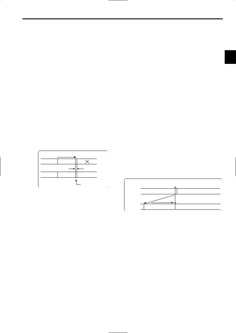
Chapter 3 Recording and playback (continued)
3-6 To take the previous cut again (RETAKE function)
The RETAKE function ensures continuity with the previous cut on the tape when shooting is resumed.
It is set by opening the <REC FUNCTION> screen from the SYSTEM SETTING page and selecting ON as the setting for the RETAKE MODE item by performing menu operations.
The RETAKE MODE item settings are described below.
ON: The retake operation is performed when the RET button on the lens is pressed while the MODE CHECK button is held down.
OFF: The RETAKE function does not operate.
If, when the rec-pause mode is established upon completion of the recording or the stop mode is established afterwards, the RET button on the lens is pressed while the MODE CHECK button is held down, the tape will be rewound to the approximate start point (a position advanced by 10 or so frames from the recording start) of the final image that was last recorded, and the rec-pause mode will be established.
If there is some leeway in the shooting time and a “NG” condition has been clearly identified, recording can be started from this point, and the cut in the NG area will be deleted.
This function is particularly useful for cutting the amount of time taken for copying onto work tapes and other such economical operations.
Direction of tape travel
Cut 1 |
Cut 2 |
Cut 3 |
|
|
Approx. 10 frames |
Cut 1 |
Cut 2 |
Cut 4 |
|
|
Cut 3 |
When the RETAKE function is to be exited
There are two ways to do this.
1)Set the unit’s POWER switch to OFF.
2)Perform a menu operation and select OFF as the RETAKE MODE item setting.
<Notes>
≥The rec-review function cannot be used unless recording lasts for one or more seconds.
≥If the VIDEO OUT OUTPUT SEL switch on the side panel is at the VTR position during the rec-review operation, the rec-review images are output not only to the viewfinder but
to the video output connector (VIDEO OUT connector) as well. 3 Use the menu operations to open the <OUTPUT SEL> screen from the SYSTEM SETTING page and set the MONI OUT MODE item to VTR to output video signals of Rec-review from the MON OUT connector as well.
Bear in mind that if back-up images are being recorded by a backup VTR that has been connected, these rec-review images will end up being recorded.
The jump function as a relevant function. For details, refer to “3-3 Scene-to-scene continuity.”
≥After executing the rec-view operation, the time code at the time of recording the following data will correspond to the settings in the REC REVIEW REGEN item (<TC/UB> screen on the VTR MENU page).
≥When the REC REVIEW REGEN item is turned ON and the rec-view operation is executed while the TCG switch is set to the R-RUN position, the time code will always be regenerated to the value on the tape.
Even if the TCG switch is set to the SET position or the F- RUN position, the time code will be rewritten to the value on the tape when the rec-veiw operation is executed after returning the switch to the R-RUN position. When recording starts, the unit regenerates the time code to the value on the tape. Even if the FIRST REC TC item of the menu (TC/UB screen of the VTR MENU page) is set to PRESET, the time code will always be regenerated to the value on the tape by executing the rec-view operation after setting the TCG switch to the R-RUN position.
 Direction of tape travel
|
Rec-pause |
Recording section |
No recorded or already recorded section |
2 to 10 sec. |
|
Rec-review operation |
Rec-pause |
|
|
Playback of recorded section |
|
3-7 To check the last few seconds of the recording
(Rec-review function)
When recording is temporarily stopped and the lens RET button is pressed, the last two seconds of the tape are automatically rewound, and the playback pictures on this part of the tape appear on the viewfinder screen. This makes it possible to check whether recording was performed properly. After the two seconds of the tape have been played back, the unit is again set to the recording start standby mode.
If the RET button is held down, a maximum of 10 seconds of the tape is rewound and played back.
The Rec-review function can be executed by opening the <SW MODE> screen from the OPERATION page and setting the RET SW items to the R. REVIEW via menu operations.
The RET button function can be allocated by opening the <USER SW> screen from the OPERATION page and selecting settings for the USER MAIN SW, USER1 SW and USER2 SW items by performing menu operations.
3-8 Normal playback and playback at different speeds
Black-and-white playback images can be viewed in the viewfinder by pressing the PLAY button. When a color monitor is connected to the unit’s VIDEO OUT connector and an HD color video monitor is connected to its MON OUT connector at the same time, the down-converted color playback images from the VIDEO OUT connector can be viewed on the color monitor while the HD high-quality images from the MON OUT connector can be viewed on the HD color video monitor.
≥In order to view these images, the OUTPUT SEL switch on the side panel must be set to the VTR position.
In addition, when the FF and REW buttons are used, the images can be played back at different speeds by establishing the cue mode (PLAY + FF), review mode (PLAY + REW), high-speed fast forward playback mode (FF) or high-speed rewind playback mode (REW).
29

Chapter 4 Adjustments and settings for recording
4-1 Multi Format
4-1-1 Video system and Recording format
The unit employs a progressive scan (full pixel reading) CCD system.
It is possible to select 11 kinds of the recording formats by combinations of the SYSTEM MODE item and the CAMERA MODE item on the <SYSTEM MODE> screen on the SYSTEM SETTING page in the setting menu.
In any recording format, the CCD operates in progressive (non-interlace) scan mode.
<Note>
When settings for SYSTEM MODE item are changed, the message “TURN POWER: OFF” is displayed in the viewfinder screen.
The settings for SYSTEM MODE item will change when the POWER switch of the unit is turned “OFF” and then turned “ON” again.
O Retain the state where the POWER switch of the unit is turned OFF for at least 5 seconds.
30
 Loading...