


SDI output Board
AJ-
Installation Guide
ENGLISH
P
E
EN
DEUTSCH
FRANÇAIS
ITALIANO
ESPAÑOL
Overview/Connector Area
Overview
AJ-YA901P/E
This SDI output board is designed for use with the AJ-BS900. Its installation in the AJ-BS900 enables digital data output using the SDI format.
Refer the installation of the SDI output board to qualified service personnel.
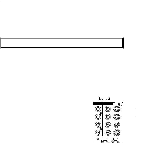
Connector Area (AJ-BS900)
Serial digital output connectors (BNC x2)
1 Output 1: SDI output
2 Output 2: SDI output
OUT |
SDI |
OUT |
|
Y/G |
|
4:2:2 |
OP3 |
|
|
||
|
|
1 SDI output |
|
|
|
|
|
B/B |
|
4:2:2 |
OP4 |
|
|
||
|
|
2 SDI output |
|
|
|
|
|
R/R |
|
OP1 |
WFM |
|
|
||
W FM |
|
OP2 |
TALL Y |
|
|
|
|
C ATION |
|
AUDIO |
|
|
|
|
|
|
PUSH |
OUT |
PUSH |
|
|
CH 1 |
CH 2 |
E - 1

Installation
Follow the steps below to install the AJ-YA901 (referred to below as “the board”) in the AJ-BS900.
1. |
Refer to the figure below, and remove |
the four screws |
4. |
Pass the ends of the cables attached to the board from |
||||||
|
from the rear panel of the AJ-BS900. |
|
|
|
|
|
the position at the bottom shown in the figure below |
|||
|
|
|
|
|
|
|
|
|
|
toward the top of the rear panel. |
|
IN |
|
OUT |
SDI |
OUT |
|
|
|
|
|
|
GEN– |
ENC |
Y/G |
4:2:2 |
OP3 |
|
|
|
|
|
|
LOCK |
|
|
|
|
|
|
|
||
|
|
1 |
|
|
|
|
|
|
|
|
|
|
ENC |
PB/B |
4:2:2 |
OP4 |
|
|
|
|
|
|
RET 1 |
|
|
|
|
|
|
|||
|
|
2 |
|
|
|
|
|
|
|
|
|
|
|
|
OP1 |
WFM |
|
|
|
|
|
|
RET 2 |
ENC |
PR/R |
|
|
FUSE |
|
|
|
|
|
|
3 |
|
|
|
|
|
|
|
|
|
|
|
|
|
|
|
|
|
AC IN |
|
|
PROMPT |
PIX |
WFM |
OP2 |
TALLY |
|
|
|
|
|
|
|
|
|
EXT DC IN |
|
|
|
|||
|
|
|
|
|
|
|
|
|
|
|
|
|
|
COMMUNICATION |
|
AUDIO |
|
|
|
|
|
|
|
|
|
PUSH |
OUT |
PUSH |
|
|
|
|
|
|
|
|
|
CH 1 |
CH 2 |
|
|
|
|
|
|
|
|
|
|
|
|
SIGNAL |
|
|
|
|
|
|
|
|
|
|
GND |
|
|
|
|
|
Screws (x4) |
|
|
|
|
|
||
2. |
Remove the |
two screws each from the |
left |
and |
right |
5. |
Connect the cables, which were inserted into the AJ- |
|||
|
side panels |
of the |
AJ-BS900 |
to |
remove |
the |
side |
|
BS900 in step 4, on the inner side of the SDI output |
|
|
panels. |
|
|
|
|
|
|
|
|
connectors. For details on the positions of these |
|
|
|
|
|
|
|
|
|
|
connectors, refer to the figure below and to “Connector |
|
|
|
|
|
|
|
|
|
|
Area” (page E-1). |
|
|
|
|
|
|
|
|
|
|
|
|
|
|
|
|
|
|
|
|
G |
E |
N |
L |
O |
C |
K |
|
|
|
E |
N |
VTR |
|
|
|
REW |
|
|
|
|
|
|
|
|
|
|
|
|
|
|
|
|
|
|
|
|
|
|
|
|
|
|
|
|
|
|
|
|
|
|
|
|
|
D |
IG |
|
IT A |
L |
T |
R |
IA |
X |
|
SA |
CR |
|
|
|
O |
|
F F |
|
|
|
|
|
OA |
NB |
L |
E |
|
|
FF |
|
|
STOP |
|
PLA |
Y |
R |
E |
C |
C |
H |
K |
|
S T AR |
T |
/ S |
|
|
|
|
|
|
|
|
|
|||||
|
|
|
C |
A |
B |
LE |
|
|
|
|
|
|
|
|
C |
O |
S |
E |
|
|
|
P |
H |
H |
S |
E |
|
|
|
|
|
|
|
|
|
|
|
|
|
|
|
|
T O |
P |
|
|
CA |
|
LL |
|
|
|||||||||||||||
O |
P |
E |
|
|
|
|
|
|
|
|
|
|
|
|
|
|
|
|
|
|
|
A |
|
|
|
|
|
|
|
|
|
|
|
|
|
|
|
|
|
|
|
|
|
|
|
|
|
|
|
|
|
|
|
|
|
|
|
|
||||||||
N |
|
|
S |
H |
O |
R |
T |
A |
L |
A |
R |
M |
|
|
|
|
|
|
|
|
|
|
|
|
|
|
|
|
O |
FF |
|
|
|
|
|
|
|
|
|
|
|
|
|
|
|
|
|
|
|
|
|
|
|
|
|
|
|
|
|
|
|
|
|
|||
|
|
|
|
|
|
|
|
|
|
|
|
|
|
|
|
|
|
|
|
|
|
|
|
|
|
|
|
|
|
|
|
|
S |
E |
T |
U |
P |
|
S |
H |
U T |
T |
E |
R |
|
VTR |
W |
|
ARNING |
|
|
|
|
|
|
|
|
T A |
L |
L Y |
|
|
||||
F |
U |
|
S |
E |
|
|
|
|
|
|
|
|
|
|
|
|
|
|
|
|
|
|
|
|
|
|
|
|
|
|
|
|
|
|
|
|
|
|
|
|
|
|
|
|
|
|
|
|
|
|
||||||||||||||||
|
|
|
|
|
|
|
F |
|
U |
S |
E |
|
|
|
|
|
|
|
|
|
|
|
|
|
|
|
|
|
|
|
|
|
|
|
|
|
|
|
|
|
|
|
|
|
|
|
|
|
A |
W |
B |
|
|
|
B |
A |
R |
|
|
|
|
|
||||
|
|
|
|
|
|
|
|
|
|
|
|
|
|
|
|
|
|
|
|
|
|
|
|
|
|
|
|
|
|
|
|
|
|
|
|
|
|
|
|
|
|
|
|
|
|
|
|
|
|
|
|
|
|
G |
A |
IN |
||||||||||
|
|
|
|
|
|
|
|
|
|
|
|
|
|
|
INTE |
|
|
RCOM |
|
|
|
|
|
M IC |
|
|
|
|
|
|
|
|
|
|
|
|
|
|
|
|
|
W |
H |
IT |
E |
|
|
|
|
|
|
|
|
|
|
|
|
|
|
|||||||
|
|
|
|
|
|
|
|
|
|
|
|
|
|
|
|
|
|
|
|
|
|
|
|
O |
|
|
(PUSH) |
|
|
|
|
|
|
|
|
|
|
|
|
|
B |
A |
L |
|
|
|
|
A |
B |
B |
|
|
|
|
|
|
|
|
|
|
|
|||||
|
|
|
|
|
|
|
|
|
|
|
|
|
|
|
|
|
|
|
|
|
|
|
|
|
N |
|
|
|
|
|
|
|
|
|
|
|
|
|
|
1 2 0 |
|
|
|
PRE |
|
|
|
|
|
|
|
|
A U |
T |
O |
|
K N |
E |
E |
|
|
|
||||
|
|
|
|
|
|
|
|
|
|
|
|
|
|
|
|
|
|
|
|
|
|
|
|
O |
F |
F |
|
|
|
|
|
|
|
|
|
|
|
1 |
00(60) |
|
|
2 50 |
|
A |
|
|
|
|
|
|
|
|
|
|
|
|
|
|
||||||||
|
|
|
|
|
|
|
|
|
|
|
|
|
|
|
|
|
|
|
|
|
|
|
|
P |
T |
T |
|
|
|
|
|
|
|
|
|
|
|
|
|
|
|
|
500 |
|
B |
|
|
|
|
|
|
|
|
|
|
|
|
|
|
|
|
|
|
|
|
|
|
|
|
|
|
|
|
|
|
|
P |
G |
M |
|
|
|
|
|
|
|
|
|
|
|
|
|
|
|
S .V |
|
|
|
1 000 |
|
|
|
|
|
|
|
|
|
|
|
|
|
|
|
|
|
|
|
|
|
P |
R |
IVA |
T |
E |
M OB |
N |
|
SS |
|
|
|
S |
.S |
|
|
2 000 |
|
|
|
|
|
|
|
M A |
|
|
|
|
|
|
|
|
|
|
|
|
|
|
|
|
|
UEP |
L |
|
|
D |
E |
T A |
P |
A |
IN |
T |
IN |
G |
||||||||
IN |
H |
E |
A |
D |
P |
O |
W |
E |
R |
|
|
|
|
|
|
|
|
|
R |
G |
|
|
|
|
S |
E Q |
|
IL |
E |
G |
A |
B |
IN |
E |
||||
O |
N |
|
|
|
O |
|
N |
|
|
|
|
|
|
|
S |
YS |
T |
E |
M |
|
|
|
|
|
|
E N |
G |
|
|
|
R |
N |
A |
L |
||||
|
|
|
|
|
|
|
|
|
|
|
|
|
K N |
E |
E |
|
|
|
|
|
|
|
|
|
|
|
|
|
||||||||||
|
|
|
|
|
|
|
|
|
|
|
|
P |
U |
S |
H |
|
|
|
|
|
|
|
|
|
|
|
|
|
|
|
|
|
|
B |
||||
|
|
|
|
|
|
|
|
|
|
|
|
|
|
|
|
|
P |
O |
IN |
T |
|
|
G |
|
A |
M M A |
|
|
|
|
|
|
||||||
|
|
|
|
|
B L A |
C |
K |
K N E E |
E |
M |
G A IN |
FILTER |
A U T O IR |
IS |
IR IS |
S L O P |
|
|
|
||||
O F F |
|
|
.PE D |
|
|
|
Side panel |
O F F |
|
|
C H E C K |
|
|
|
|
|
|
|
B a s e |
S ta |
|
A J - |
|
|
|
|
|
|
tio n |
|
|
3. Remove the two screws from the bottom panel of the AJ-BS900 to remove the bottom panel.
Bottom panel
Screws (x2)
6. Remove the four screws on the front panel of the AJBS900, and pull off the front panel cover. (The screws cannot be removed from the front panel cover.)
|
|
|
|
|
|
|
|
Screws (x4) |
|
|
|
||||
|
|
|
GENLOCK |
|
VTR |
REW |
FF |
STOP |
|
PLAY |
REC CHK |
|
START / STOP |
CALL |
|
|
|
|
|
ENABLE |
|
|
|||||||||
|
|
|
|
|
ON |
|
|
|
|
|
|
|
|
|
|
|
DIGITAL TRIAX |
SC |
OFF |
H |
|
|
|
|
|
|
|
|
|
|
|
|
|
COARSE |
|
PHASE |
OFF |
|
|
|
|
|
VTR |
WARNING |
|
|
TALLY |
|
|
|
|
|
|
|
|
|
|
|
|
|
|||
|
CABLE |
|
|
|
SET UP |
|
|
SHUTTER |
|
|
|
|
AWB |
BAR |
GAIN |
OPEN |
SHORT ALARM |
|
|
|
|
|
|
|
|
|
WHITE |
|
|
|
|
|
|
|
|
|
|
|
|
|
|
|
|
|
|
|
|
|
|
|
|
|
|
|
|
|
|
|
BAL |
|
ABB |
AUTO KNEE |
|
|
|
|
|
|
|
|
|
|
|
PRE |
|
|
|
||
FUSE |
FUSE |
INTERCOM |
|
MIC |
|
|
|
|
|
|
|
|
|
|
|
|
(PUSH) |
|
|
120 |
250 |
|
A |
|
|
|
|
||||
|
|
|
|
ON |
|
|
100(60) |
500 |
B |
|
|
|
|
||
|
|
|
|
|
|
|
|
|
|
|
|||||
|
|
|
|
OFF |
|
|
S.V |
|
1000 |
|
|
|
PAINTING |
|
|
|
|
|
|
PTT |
|
|
S.S. |
|
2000 |
|
|
|
|
||
|
|
|
|
|
|
|
|
|
|
|
|
GAIN |
|
||
|
|
PGM |
|
|
MON SEL |
|
|
DETAIL |
|
|
|
|
|
|
|
|
|
|
PRIVATE |
|
|
|
|
|
|
|
ENABLE |
|
|||
|
|
|
B |
SUP |
|
|
|
|
|
|
|
||||
|
|
|
|
|
G |
|
SEQ |
|
|
|
|
|
R |
|
B |
|
|
|
|
|
R |
|
ENG |
|
|
|
|
|
|
||
MAIN |
HEAD POWER |
|
|
SYSTEM |
KNEE |
|
|
|
|
|
|
|
|
BLACK |
|
ON |
ON |
|
|
|
POINT |
|
|
GAMMA |
|
|
|
|
|
|
|
|
PUSH |
|
|
|
|
|
|
|
|
|
|
|
|
||
|
|
|
|
|
|
|
|
|
|
|
|
|
AUTO IRIS |
IRIS |
|
|
|
|
|
|
|
|
|
|
|
|
|
GAIN |
FILTER |
||
|
|
|
|
|
|
|
|
|
|
|
|
|
|
||
|
|
|
|
|
KNEE |
|
|
M.PED |
|
|
|
|
|
|
|
|
|
|
|
|
SLOPE |
|
|
|
CHECK |
|
|
|
|
|
|
|
|
|
|
|
|
|
|
|
|
|
|
|
|
|
|
OFF |
OFF |
Base |
Station |
AJ- |
ENGLISH
E - 2

Installation
7. While referring to the figure below, pass the other ends
of the cables connected in step 5 from the bottom toward the front panel top.
8. Remove the screw from the front panel of the cover removed from the AJ-BS900, and disengage the metal piece shown in the figure below. (The screw cannot be removed from the metal piece.)
10 .
11 .
Metal piece
Screw
PUSH
9. Connect the ends of the cables which were passed 12 . from the bottom in step 7 to the board so that they are
aligned in the directions shown in the figure below.
Insert the board into the left-most slot of the AJ-BS900, and reattach the metal piece, which was disengaged in
step 8, to its original position. When securing the metal piece, ensure that the cables are not pinched.
Pull out the excess lengths of the cables toward the bottom, and anchor the cables using cable clamps so that no slack remains in the cables.
Cable clamps
Return the front panel cover, bottom panel and side panels in this order to their original positions, and secure them using the respective screws.
E - 3

Specifications
Specifications
GENERAL
Weight: |
170 g |
Dimensions: |
230 (W) x 113 (H) x 20 (D) mm |
VIDEO OUTPUT
Serial digital output connectors: BNC x 2
SERIAL OUT 1: SDI output connector SERIAL OUT 2: SDI output connector
SDI: Compliant with SMPTE 259M-C standard
AUDIO OUTPUT
Serial digital output connectors: Compliant with SMPTE 259M-C/SMPTE 272M-A standards
ENGLISH
E - 4

Übersicht/Anschlussbereich
Übersicht
AJ-YA901P/E
Diese SDI-Ausgangsplatine ist für den Einsatz mit dem AJ-BS900 vorgesehen. Ihr Einbau in den AJ-BS900 ermöglicht die digitale Datenausgabe im SDI-Format.
Überlassen Sie den Einbau der SDI-Ausgangsplatine qualifiziertem Wartungspersonal.
Anschlussbereich (AJ-BS900)
Serielle Digitalausgänge (BNC x 2)
1 Ausgang 1: SDI-Ausgang
2 Ausgang 2: SDI-Ausgang
OUT |
SDI OUT |
|
|
Y/G |
|
4:2:2 |
OP3 |
|
|
||
|
|
1 SDI-Ausgang |
|
|
|
|
|
B/B |
|
4:2:2 |
OP4 |
|
|
||
|
|
2 SDI-Ausgang |
|
|
|
|
|
R/R |
|
OP1 |
WFM |
|
|
||
W FM |
|
OP2 |
TALL Y |
|
|
|
|
C ATION |
|
AUDIO |
|
|
|
|
|
|
PUSH |
OUT |
PUSH |
|
|
CH 1 |
CH 2 |
D - 1

Installation
Führen Sie die folgenden Schritte aus, um die Platine AJ-YA901 in den AJ-BS900 einzubauen.
1. Die in der |
nachstehenden |
Abbildung |
gezeigten |
vier |
4. Die Enden der an der Platine angebrachten Kabel von |
|||
Schrauben |
von |
der |
Rückwand |
des |
AJ-BS900 |
der in der folgenden Abbildung gezeigten Position an |
||
entfernen. |
|
|
|
|
|
|
|
der Unterseite zur Oberseite der Rückwand führen. |
|
IN |
|
OUT |
SDI |
OUT |
|
|
|
|
GEN– |
ENC |
Y/G |
4:2:2 |
OP3 |
|
|
|
|
LOCK |
|
|
|
|
|
||
|
|
1 |
|
|
|
|
|
|
|
|
ENC |
PB/B |
4:2:2 |
OP4 |
|
|
|
|
RET 1 |
|
|
|
|
|||
|
|
2 |
|
|
|
|
|
|
|
|
|
|
OP1 |
WFM |
|
|
|
|
RET 2 |
ENC |
PR/R |
|
|
FUSE |
|
|
|
|
3 |
|
|
|
|
|
|
|
|
|
|
|
|
|
|
AC IN |
|
PROMPT |
PIX |
WFM |
OP2 |
TALLY |
|
|
|
|
|
|
|
EXT DC IN |
|
|||
|
|
|
|
|
|
|
|
|
|
|
COMMUNICATION |
|
AUDIO |
|
|
|
|
|
|
|
|
PUSH |
OUT PUSH |
|
|
|
|
|
|
|
|
CH 1 |
CH 2 |
|
|
|
|
|
|
|
|
|
SIGNAL |
|
|
|
|
|
|
|
|
GND |
|
Schrauben (x 4)
2. Je zwei Schrauben von der linken und rechten Seitenwand des AJ-BS900 entfernen, und die Seitenwände abnehmen.
|
|
|
|
|
|
|
|
|
|
|
|
|
|
|
|
|
|
|
|
G |
E |
N |
L |
O |
C |
K |
|
|
|
E |
N |
VTR |
|
|
|
REW |
|
|
|
|
|
|
|
|
|
|
|
|
|
|
|
|
|
|
|
|
|
|
|
|
|
|
|
|
|
|
|
|
|
|
|
|
|
D |
IG |
|
IT A |
L |
T |
R |
IA |
X |
|
SA |
CR |
|
|
|
O |
|
F F |
|
|
|
|
|
OA |
NB |
L |
E |
|
|
FF |
|
|
STOP |
|
PLA |
Y |
R |
E |
C |
C |
H |
K |
|
S T AR |
T |
/ S |
|
|
|
|
|
|
|
|
|
|||||
|
|
|
C |
A |
B |
LE |
|
|
|
|
|
|
|
|
C |
O |
S |
E |
|
|
|
P |
H |
H |
S |
E |
|
|
|
|
|
|
|
|
|
|
|
|
|
|
|
|
T O |
P |
|
|
CA |
|
LL |
|
|
|||||||||||||||
O |
P |
E |
|
|
|
|
|
|
|
|
|
|
|
|
|
|
|
|
|
|
|
A |
|
|
|
|
|
|
|
|
|
|
|
|
|
|
|
|
|
|
|
|
|
|
|
|
|
|
|
|
|
|
|
|
|
|
|
|
||||||||
N |
|
|
S |
H |
O |
R |
T |
A |
L |
A |
R |
M |
|
|
|
|
|
|
|
|
|
|
|
|
|
|
|
|
O |
FF |
|
|
|
|
|
|
|
|
|
|
|
|
|
|
|
|
|
|
|
|
|
|
|
|
|
|
|
|
|
|
|
|
|
|||
|
|
|
|
|
|
|
|
|
|
|
|
|
|
|
|
|
|
|
|
|
|
|
|
|
|
|
|
|
|
|
|
|
S |
E |
T |
U |
P |
|
S |
H |
U T |
T |
E |
R |
|
VTR |
W |
|
ARNING |
|
|
|
|
|
|
|
|
T A |
L |
L Y |
|
|
||||
F |
U |
|
S |
E |
|
|
|
|
|
|
|
|
|
|
|
|
|
|
|
|
|
|
|
|
|
|
|
|
|
|
|
|
|
|
|
|
|
|
|
|
|
|
|
|
|
|
|
|
|
|
||||||||||||||||
|
|
|
|
|
|
|
F |
|
U |
S |
E |
|
|
|
|
|
|
|
|
|
|
|
|
|
|
|
|
|
|
|
|
|
|
|
|
|
|
|
|
|
|
|
|
|
|
|
|
|
A |
W |
B |
|
|
|
B |
A |
R |
|
|
|
|
|
||||
|
|
|
|
|
|
|
|
|
|
|
|
|
|
|
|
|
|
|
|
|
|
|
|
|
|
|
|
|
|
|
|
|
|
|
|
|
|
|
|
|
|
|
|
|
|
|
|
|
|
|
|
|
|
G |
A |
IN |
||||||||||
|
|
|
|
|
|
|
|
|
|
|
|
|
|
|
INTE |
|
|
RCOM |
|
|
|
|
|
M IC |
|
|
|
|
|
|
|
|
|
|
|
|
|
|
|
|
|
W |
H |
IT |
E |
|
|
|
|
|
|
|
|
|
|
|
|
|
|
|||||||
|
|
|
|
|
|
|
|
|
|
|
|
|
|
|
|
|
|
|
|
|
|
|
|
O |
|
|
(PUSH) |
|
|
|
|
|
|
|
|
|
|
|
|
|
B |
A |
L |
|
|
|
|
A |
B |
B |
|
|
|
|
|
|
|
|
|
|
|
|||||
|
|
|
|
|
|
|
|
|
|
|
|
|
|
|
|
|
|
|
|
|
|
|
|
|
N |
|
|
|
|
|
|
|
|
|
|
|
|
|
|
1 2 0 |
|
|
|
PRE |
|
|
|
|
|
|
|
|
A U |
T |
O |
|
K N |
E |
E |
|
|
|
||||
|
|
|
|
|
|
|
|
|
|
|
|
|
|
|
|
|
|
|
|
|
|
|
|
O |
F |
F |
|
|
|
|
|
|
|
|
|
|
|
1 |
00(60) |
|
|
2 50 |
|
A |
|
|
|
|
|
|
|
|
|
|
|
|
|
|
||||||||
|
|
|
|
|
|
|
|
|
|
|
|
|
|
|
|
|
|
|
|
|
|
|
|
P |
T |
T |
|
|
|
|
|
|
|
|
|
|
|
|
|
|
|
|
500 |
|
B |
|
|
|
|
|
|
|
|
|
|
|
|
|
|
|
|
|
|
|
|
|
|
|
|
|
|
|
|
|
|
|
P |
G |
M |
|
|
|
|
|
|
|
|
|
|
|
|
|
|
|
S .V |
|
|
|
1 000 |
|
|
|
|
|
|
|
|
|
|
|
|
|
|
|
|
|
|
|
|
|
P |
R |
IVA |
T |
E |
M OB |
N |
|
SS |
|
|
|
S |
.S |
|
|
2 000 |
|
|
|
|
|
|
|
M A |
|
|
|
|
|
|
|
|
|
|
|
|
|
|
|
|
|
UEP |
L |
|
|
D |
E |
T A |
P |
A |
IN |
T |
IN |
G |
||||||||
IN |
H |
E |
A |
D |
P |
O |
W |
E |
R |
|
|
|
|
|
|
|
|
|
R |
G |
|
|
|
|
S |
E Q |
|
IL |
E |
G |
A |
B |
IN |
E |
||||
O |
N |
|
|
|
O |
|
N |
|
|
|
|
|
|
|
S |
YS |
T |
E |
M |
|
|
|
|
|
|
E N |
G |
|
|
|
R |
N |
A |
L |
||||
|
|
|
|
|
|
|
|
|
|
|
|
|
K N |
E |
E |
|
|
|
|
|
|
|
|
|
|
|
|
|
||||||||||
|
|
|
|
|
|
|
|
|
|
|
|
P |
U |
S |
H |
|
|
|
|
|
|
|
|
|
|
|
|
|
|
|
|
|
|
B |
||||
|
|
|
|
|
|
|
|
|
|
|
|
|
|
|
|
|
P |
O |
IN |
T |
|
|
G |
|
A |
M M A |
|
|
|
|
|
|
||||||
|
|
|
|
B L A C |
K |
K N E E |
E |
M |
G A IN |
A U T O IR IS |
IR IS |
S L O P |
|
FILTER |
|||
O F F |
|
|
.PE D |
|
Seitenwand |
O F F |
|
|
C H E C K |
|
5. Die in Schritt 4 in den AJ-BS900 eingeführten Kabel an der Innenseite der SDI-Ausgangsbuchsen anschließen. Einzelheiten zur Lage dieser Buchsen sind der folgenden Abbildung und dem Abschnitt “Anschlussbereich” (Seite D-1) zu entnehmen.
B |
a |
s e |
S |
ta |
tio n |
A |
J |
- |
|
|
|
|
|
3. Zwei Schrauben von der Bodenplatte des AJ-BS900 entfernen, und die Bodenplatte abnehmen.
Bodenplatte |
Schrauben (x 2)
6. Die vier Schrauben von der Frontplatte des AJ-BS900 entfernen, und die Frontplattenabdeckung abziehen.
(Die Schrauben können nicht von der Frontplattenabdeckung entfernt werden.)
|
|
|
|
|
|
|
Schrauben (x 4) |
|
|
|
|||||
|
|
|
GENLOCK |
|
VTR |
REW |
FF |
STOP |
|
PLAY |
REC CHK |
|
START / STOP |
CALL |
|
|
|
|
|
ENABLE |
|
|
|||||||||
|
|
|
|
|
ON |
|
|
|
|
|
|
|
|
|
|
|
DIGITAL TRIAX |
SC |
OFF |
H |
|
|
|
|
|
|
|
|
|
|
|
|
|
COARSE |
|
PHASE |
OFF |
|
|
|
|
|
VTR |
WARNING |
|
|
TALLY |
|
|
|
|
|
|
|
|
|
|
|
|
|
|||
|
CABLE |
|
|
|
SET UP |
|
|
SHUTTER |
|
|
|
|
AWB |
BAR |
GAIN |
OPEN |
SHORT ALARM |
|
|
|
|
|
|
|
|
|
WHITE |
|
|
|
|
|
|
|
|
|
|
|
|
|
|
|
|
|
|
|
|
|
|
|
|
|
|
|
|
|
|
|
BAL |
|
ABB |
AUTO KNEE |
|
|
|
|
|
|
|
|
|
|
|
PRE |
|
|
|
||
FUSE |
FUSE |
INTERCOM |
|
MIC |
|
|
|
|
|
|
|
|
|
|
|
|
(PUSH) |
|
|
120 |
250 |
|
A |
|
|
|
|
||||
|
|
|
|
ON |
|
|
100(60) |
500 |
B |
|
|
|
|
||
|
|
|
|
|
|
|
|
|
|
|
|||||
|
|
|
|
OFF |
|
|
S.V |
|
|
1000 |
|
|
|
PAINTING |
|
|
|
|
|
PTT |
|
|
S.S. |
|
2000 |
|
|
|
|
||
|
|
|
|
|
|
|
|
|
|
|
|
GAIN |
|
||
|
|
PGM |
|
|
MON SEL |
|
|
DETAIL |
|
|
|
|
|
|
|
|
|
|
PRIVATE |
|
|
|
|
|
|
|
ENABLE |
|
|||
|
|
|
B |
SUP |
|
|
|
|
|
|
|
||||
|
|
|
|
|
G |
|
SEQ |
|
|
|
|
|
R |
|
B |
|
|
|
|
|
R |
|
ENG |
|
|
|
|
|
|
||
MAIN |
HEAD POWER |
|
|
SYSTEM |
KNEE |
|
|
|
|
|
|
|
|
BLACK |
|
ON |
ON |
|
|
|
POINT |
|
|
GAMMA |
|
|
|
|
|
|
|
|
PUSH |
|
|
|
|
|
|
|
|
|
|
|
|
||
|
|
|
|
|
|
|
|
|
|
|
|
|
AUTO IRIS |
IRIS |
|
|
|
|
|
|
|
|
|
|
|
|
|
GAIN |
FILTER |
||
|
|
|
|
|
|
|
|
|
|
|
|
|
|
||
|
|
|
|
|
KNEE |
|
|
M.PED |
|
|
|
|
|
|
|
|
|
|
|
|
SLOPE |
|
|
|
CHECK |
|
|
|
|
|
|
|
|
|
|
|
|
|
|
|
|
|
|
|
|
|
|
OFF |
OFF |
Base |
Station |
AJ- |
DEUTSCH
D - 2

Installation
7. Die anderen Enden der in Schritt 5 angeschlossenen
Kabel gemäß der folgenden Abbildung von der Unterseite zur Oberseite der Frontplatte führen.
8. Die markierte Schraube von der freigelegten Vorderseite des AJ-BS900 entfernen, und die in der folgenden Abbildung gezeigte Metallplatte abnehmen. (Die Schraube kann nicht von der Metallplatte entfernt werden.)
10 .
11 .
Die Platine in den äußersten linken Steckplatz des AJBS900 einführen, und die in Schritt 8 abgenommene
Metallplatte wieder an ihrem ursprünglichen Platz anbringen. Beim Befestigen der Metallplatte darauf achten, dass die Kabel nicht eingeklemmt werden.
Die überschüssigen Kabellängen nach unten ziehen, und die Kabel mit den Kabelklemmen so verankern, dass sie keinen Durchhang haben.
Kabelklemmen
Metallplatte
Schraube
PUSH
9. Die Enden der in Schritt 7 von der Unterseite eingeführten Kabel so an die Platine anschließen, dass die Kabel gemäß der folgenden Abbildung verlaufen.
12 . Frontplattenabdeckung, Bodenplatte und Seitenwände in dieser Reihenfolge wieder anbringen und mit den jeweiligen Schrauben befestigen.
D - 3

Technische Daten
Technische Daten
ALLGEMEINES
Gewicht: |
170 g |
Abmessungen: |
230 (B) x 113 (H) x 20 (T) mm |
VIDEO-AUSGÄNGE
Serielle Digitalausgänge: |
BNC x 2 |
|
|
SERIAL OUT 1: SDI-Ausgang |
|
|
SERIAL OUT 2: SDI-Ausgang |
|
|
SDI: |
Entspricht der Norm SMPTE 259M-C |
AUDIO-AUSGANG
Serieller Digitalausgang: Entspricht den Normen SMPTE 259M-C/SMPTE 272M-A
DEUTSCH
D - 4
 Loading...