


Operating Instructions
Memory Card Camera-Recorder
Model No. AJ-PX800G
Before operating this product, please read the instructions carefully and save this manual for future use.
W1014HM1065 -YI |
ENGLISH |
|
VQT5L20A-1(E) |
Read this first!
Read this first!


 indicates safety information.
WARNING:
•To reduce the risk of fire, do not expose this equipment to rain or moisture.
•To reduce the risk of fire, keep this equipment away from all liquids. Use and store only in locations which are not exposed to the risk of dripping or splashing liquids, and do not place any liquid containers on top of the equipment.
WARNING:
Always keep memory cards (optional accessory) out of the reach of babies and small children.
CAUTION:
Do not remove panel covers by unscrewing. No user serviceable parts inside. Refer servicing to qualified service personnel.
CAUTION:
To reduce the risk of fire and annoying interference, use the recommended accessories only.
CAUTION:
To reduce the risk of fire, refer mounting of the optional interface boards to qualified service personnel.
CAUTION:
Do not jar, swing, or shake the unit by its handle while the conversion lens or another accessory is attached.
Due to the added weight of the conversion lens, any strong jolt to the handle may damage the unit or result in personal injury.
CAUTION:
In order to maintain adequate ventilation, do not install or place this unit in a bookcase, built-in cabinet or any other confined space. To prevent risk of fire hazard due to overheating, ensure that curtains and any other materials do not obstruct the ventilation.
CAUTION:
Do not lift the unit by its handle while the tripod is attached. When the tripod is attached, its weight will also affect the unit’s handle, possibly causing the handle to break and hurting the user. To carry the unit while the tripod is attached, take hold of the tripod.
CAUTION:
Excessive sound pressure from earphones and headphones can cause hearing loss.
CAUTION:
Do not leave the unit in direct contact with the skin for long periods of time when in use.
Low temperature burn injuries may be suffered if the high temperature parts of this unit are in direct contact with the skin for long periods of time.
When using the equipment for long periods of time, make use of the tripod.
CAUTION:
A coin type battery is installed inside of the unit. Do not store the unit in temperatures over 60 °C (140 °F).
Do not leave the unit in an automobile exposed to direct sunlight for a long period of time with doors and windows closed.
– 2 –

Read this first!


 indicates safety information.
FCC NOTICE (USA)
Declaration of Conformity
Model Number: |
AJ-PX800G |
Trade Name: |
Panasonic |
Responsible Party: |
Panasonic Corporation of North America |
|
Two Riverfront Plaza, Newark, NJ 07102 |
Support contact: |
1-800-524-1448 |
This device complies with Part 15 of the FCC Rules. Operation is subject to the following two conditions:
(1) This device may not cause harmful interference, and (2) this device must accept any interference received, including interference that may cause undesired operation.
CAUTION:
This equipment has been tested and found to comply with the limits for a Class B digital device, pursuant to Part 15 of the FCC Rules. These limits are designed to provide reasonable protection against harmful interference in a residential installation. This equipment generates, uses and can radiate radio frequency energy and, if not installed and used in accordance with the instructions, may cause harmful interference to radio communications. However, there is no guarantee that interference will not occur in a particular installation. If this equipment does cause harmful interference to radio or television reception, which can be determined by turning the equipment off and on, the user is encouraged to try to correct the interference by one or more of the following measures:
•Reorient or relocate the receiving antenna.
•Increase the separation between the equipment and receiver.
•Connect the equipment into an outlet on a circuit different from that to which the receiver is connected.
•Consult the dealer or an experienced radio/TV technician for help.
The user may find the booklet “Something About Interference” available from FCC local regional offices helpful.
Warning:
To assure continued FCC emission limit compliance, follow the attached installation instructions and the user must use only shielded interface cables when connecting to host computer or peripheral devices. Also, any unauthorized changes or modifications to this equipment could void the user’s authority to operate this device.
NOTIFICATION (Canada)
CAN ICES-3(B)/NMB-3(B)
A rechargeable battery that is recyclable powers the product you have purchased.
– 3 –

Read this first!
EMC NOTICE FOR THE PURCHASER/USER OF THE APPARATUS
1.Applicable standards and operating environment
The apparatus is compliant with:
 standards EN55103-1 and EN55103-2, and
 electromagnetic environments E1, E2, E3 and E4.
2.Pre-requisite conditions to achieving compliance with the above standards
<1> Peripheral equipment to be connected to the apparatus and special connecting cables
 The purchaser/user is urged to use only equipment which has been recommended by us as peripheral equipment to be connected to the apparatus.
 The purchaser/user is urged to use only the connecting cables described below.
<2> For the connecting cables, use shielded cables which suit the intended purpose of the apparatus.
 Video signal connecting cables
Use double-shielded coaxial cables, which are designed for 75-ohm type high-frequency applications, for SDI (Serial Digital Interface).
Coaxial cables, which are designed for 75-ohm type high-frequency applications, are recommended for analog video signals.
 Audio signal connecting cables
If your apparatus supports AES/EBU serial digital audio signals, use cables designed for AES/EBU.
Use shielded cables, which provide quality performance for high-frequency transmission applications, for analog audio signals.
 Other connecting cables
Use shielded cables, which provide quality performance for high-frequency applications, such as connecting cables for IEEE1394 or USB.
 When connecting to the HDMI signal terminal, use multilayer shielded cables, which provide quality performance for high-frequency applications.
 When connecting to the DVI signal terminal, use a cable with a ferrite core.
 If your apparatus is supplied with ferrite core(s), they must be attached on cable(s) following instructions in this manual.
3.Performance level
The performance level of the apparatus is equivalent to or better than the performance level required by these standards.
However, the apparatus may be adversely affected by interference if it is being used in an EMC environment, such as an area where strong electromagnetic fields are generated (by the presence of signal transmission towers, cellular phones, etc.). In order to minimize the adverse effects of the interference on the apparatus in cases like this, it is recommended that the following steps be taken with the apparatus being affected and with its operating environment:
1.Place the apparatus at a distance from the source of the interference.
2.Change the direction of the apparatus.
3.Change the connection method used for the apparatus.
4.Connect the apparatus to another power outlet where the power is not shared by any other appliances.
– 4 –
Read this first!
AEEE Yönetmeliğine Uygundur.
AEEE Complies with Directive of Turkey.
Декларація про Відповідність Вимогам Технічного Регламенту Обмеження Використання деяких Небезпечних Речовин в
електричному та електронному обладнанні (затвердженого Постановою №1057 Кабінету Міністрів України)
Виріб відповідає вимогам Технічного Регламенту Обмеження Використання деяких Небезпечних Речовин в електричному та електронному обладнанні (ТР ОВНР).
Вміст небезпечних речовин у випадках, не обумовлених в Додатку №2 ТР ОВНР, :
1.свинець(Pb) – не перевищує 0,1 % ваги речовини або в концентрації до 1000 частин на мільйон;
2.кадмій (Cd) – не перевищує 0,01 % ваги речовини або в концентрації до 100 частин на мільйон;
3.ртуть(Hg) – не перевищує 0,1 % ваги речовини або в концентрації до 1000 частин на мільйон;
4.шестивалентний хром (Cr6+) – не перевищує 0,1 % ваги речовини або в концентрації до 1000 частин на мільйон;
5.полібромбіфеноли (PBB) – не перевищує 0,1 % ваги речовини або в концентрації до 1000 частин на мільйон;
6.полібромдефенілові ефіри (PBDE) – не перевищує 0,1 % ваги речовини або в концентрації до 1000 частин на мільйон.
For USA-California Only
This product contains a CR Coin Cell Lithium Battery which contains Perchlorate Material – special handling may apply. See www.dtsc.ca.gov/hazardouswaste/perchlorate
Manufactured by: Panasonic Corporation, Osaka, Japan
Importer’s name and address of pursuant to EU rules:
Panasonic Marketing Europe GmbH
Panasonic Testing Centre
Winsbergring 15, 22525 Hamburg, Germany
EU
TO REMOVE BATTERY
Main Power Battery (Ni-Cd / Ni-MH / Li-ion Battery)
•To detach the battery, please proceed in the reverse order of the installation method described in this manual.
•If a battery made by any other manufacturer is to be used, check the Operating Instructions accompanying the battery.
Back-up Battery (Lithium Battery)
• For the removal of the battery for disposal at the end of its service life, please consult your dealer.
Battery recycling symbol (valid only in Taiwan)
– 5 –

ffSDXC logo is a trademark of SD-3C, LLC.
ffHDMI, HDMI logo, and High-Definition Multimedia Interface are trademarks or registered trademarks of HDMI Licensing LLC in the United States and/ or other countries.
ffMMC (Multi Media Card) is a registered trademark of Infineon Technologies AG.
ffMicrosoft® and Windows® are registered trademarks or trademarks of Microsoft Corporation in the United States and/or other countries. ffScreenshots are used according to Microsoft Corporation guidelines.
ffApple, Macintosh, Mac OS, QuickTime, iPad, and iPhone are trademarks or registered trademarks of Apple Inc. in the United States and/or other countries.
ffJava and all Java-based trademarks are trademarks or registered trademarks of Sun Microsystems, Inc. in the United States. ffUniSlot is a registered trademark of Ikegami Tsushinki Co., LTD.
ffAll other names, company names, product names, etc., contained in this instruction manual are trademarks or registered trademarks of their respective owners.
ffThis product is licensed under the AVC Patent Portfolio License. All other acts are not licensed except private use for personal and non-profit purposes such as what are described below.
-- To record video in compliance with the AVC standard (AVC Video)
-- To play back AVC Video that was recorded by a consumer engaged in a personal and non-commercial activity -- To play back AVC Video that was obtained from a video provider licensed to provide the video
Visit the MPEG LA, LLC website (http://www.mpegla.com/) for details. ffUse of DCF Technologies under license from Multi-Format, Inc.
How to read this document
rr Illustrations
ffIllustrations of the camera, menu screens, and other items, may vary from the actual items.
rr Conventions used in this manual
ffWords and phrases in [ ] brackets indicate content displayed in the viewfinder or SmartUI.
ffWords and phrases in < > brackets indicate design text used on this camera, such as button names.
rr Reference pages
ffReference pages in this document are indicated by (page 00).
rr Terminology
ffSD memory card, SDHC memory card, and SDXC memory card are referred to as “SD memory card”.
ffA memory card with the “P2” logo such as AJ P2E064FG memory card (optional) is referred to as a “P2 memory card”.
ffA memory card with the “microP2” logo such as “AJ P2M032AG” memory card (optional) is referred to as a “microP2 memory card”. To use, insert it into the microP2 card adaptor AJ P2AD1G (optional).
ffP2 memory card and microP2 memory card are referred to only as “P2 card” unless distinguished otherwise. ffMedia such as external hard disk drives (HDD) connected to USB are referred to as “storage devices”. ffVideo that is created during a single recording operation is referred to as a “clip”.
– 6 –

Contents
Contents
Read this first! 2
Chapter 1 Overview |
|
9 |
Before using the camera |
|
10 |
Setting the region of use (setting the frame frequency, etc.) |
|
|
|
|
11 |
Accessories |
|
12 |
Use of the camera on a system |
|
13 |
Basic configuration devices |
|
13 |
Expanded configuration devices |
|
13 |
Accessories |
|
13 |
Chapter 2 Description of parts |
|
14 |
Power supply and accessory mounting section |
|
15 |
Audio (input) function section |
|
17 |
Audio (output) function section |
|
18 |
Shooting and recording/playback functions section |
|
19 |
Shooting and recording (camera unit) |
|
19 |
Shooting and recording/playback functions section (recording |
|
|
unit) |
|
20 |
Menu operation section and thumbnail operation section |
|
22 |
Time code section |
|
23 |
Warning and status display section |
|
24 |
SmartUI display ([HOME] screen) |
|
25 |
Chapter 3 |
Preparation |
|
26 |
Power supply |
|
|
27 |
Using batteries |
|
27 |
|
Mounting and setting battery |
|
27 |
|
Using external DC power supply |
|
28 |
|
Mounting and adjusting the lens |
|
30 |
|
Mounting the lens |
|
30 |
|
Lens flange back adjustment |
|
30 |
|
White shading compensation |
|
32 |
|
Chromatic aberration compensation function (CAC) |
|
33 |
|
Preparing for audio input |
|
36 |
|
Using front microphone |
|
36 |
|
When using a wireless microphone receiver |
|
36 |
|
Using audio devices |
|
37 |
|
Mounting accessories |
|
38 |
|
Attaching a tripod |
|
38 |
|
Attaching the shoulder strap |
|
38 |
|
Attaching the rain cover |
|
39 |
|
Connecting the <DC OUT> terminal to the external |
|
|
|
recording start/stop switch |
|
40 |
|
Setting the date/time of the internal clock |
|
41 |
|
P2 card |
|
|
42 |
Inserting a P2 card |
|
42 |
|
Removing a P2 card |
|
42 |
|
Preventing accidental erasure |
|
43 |
|
P2 card access LEDs and status of P2 cards |
|
43 |
|
P2 card recording time |
|
43 |
|
CPS (Content Protection System) |
|
44 |
|
How to handle data recorded on P2 cards |
|
45 |
|
Tally lamp |
|
|
46 |
Chapter 4 |
Shooting |
|
47 |
Basic procedures |
|
48 |
|
Preparation |
|
|
48 |
For shooting |
|
|
49 |
Standard recording |
|
50 |
|
Native recording |
|
50 |
|
Selecting the resolution, codec, and video format for recording |
|
50 |
|
Adjustable settings when shooting |
|
52 |
|
Focus assist function |
|
52 |
|
Level gauge function |
|
53 |
|
Adjusting the white and black balance |
|
54 |
|
Adjusting the white balance |
|
54 |
|
Adjusting the black balance |
|
55 |
|
Setting the electronic shutter |
|
57 |
|
Setting the shutter mode and speed |
|
57 |
|
Setting the synchro scan mode |
|
58 |
|
Flash band compensation (FBC) function |
|
59 |
|
Setting the flash band compensation function |
|
59 |
|
Assigning functions to USER buttons |
|
60 |
|
Selectable functions |
|
60 |
Selecting audio input and adjusting recording levels |
|
61 |
Selecting audio input signals |
|
61 |
Adjusting the recording level |
|
61 |
Selecting the <F.AUDIO LEVEL> dial function |
|
61 |
Adjusting image quality |
|
62 |
Detail function |
|
62 |
Skin tone function |
|
62 |
RB gain control function |
|
63 |
Chroma setting function |
|
63 |
Matrix function |
|
63 |
Color correction function |
|
64 |
Black control function |
|
64 |
Gamma function |
|
64 |
Knee function |
|
64 |
High color function |
|
65 |
White clip function |
|
65 |
Special recording functions |
|
66 |
Pre-recording |
|
66 |
Interval recording |
|
66 |
One-shot recording |
|
67 |
Loop recording |
|
67 |
One-clip recording |
|
68 |
Simultaneous recording |
|
69 |
Hot swap recording |
|
69 |
Recording check function |
|
70 |
Shot mark recording function |
|
70 |
Text memo recording function |
|
70 |
Multi formats |
|
71 |
Selecting recording signals |
|
71 |
System modes and recording functions |
|
71 |
List of recording settings and recording functions |
|
74 |
Selecting video output |
|
74 |
Recording/playback and output format list |
|
75 |
Dual codec recording |
|
77 |
Dual codec recording setting |
|
77 |
Recording the proxy data |
|
78 |
Recording to the SD memory card |
|
78 |
Checking the proxy data |
|
79 |
Error displays about proxy data recordings |
|
80 |
Streaming function |
|
81 |
Setting the network connection |
|
81 |
Using the streaming function |
|
81 |
List of system modes and supported streaming output |
|
81 |
List of streaming modes and resolution/frame rates |
|
82 |
Handling setting data |
|
83 |
Setting data file configuration |
|
83 |
Handling SD memory cards |
|
83 |
Performing operations on SD memory cards |
|
84 |
How to use user data |
|
84 |
How to use scene file data |
|
85 |
How to restore the scene file or menu setting status to the |
|
|
factory settings |
|
86 |
Saving to an SD memory card and loading saved data |
|
86 |
Selection of external reference signal and generator lock |
|
|
setting |
|
88 |
Locking the video signal to the external reference signal |
|
88 |
Setting the time data |
|
89 |
Definition of time data |
|
89 |
Recording of time codes and user bits |
|
89 |
User bits settings |
|
92 |
How to input user bits |
|
93 |
Setting the time code |
|
94 |
Externally locking the time code |
|
95 |
Supplying the time code externally |
|
96 |
Connecting and setting the genlock and time code input/output |
97 |
|
Setting and displaying the counter |
|
97 |
Convenient shooting functions |
|
98 |
Scan reverse shooting |
|
98 |
Zebra patterns display |
|
98 |
Displaying the center marker |
|
98 |
Displaying the safety zone marker |
|
98 |
Displaying frame marker |
|
99 |
Checking and displaying the shooting status |
|
99 |
Changing image size |
|
99 |
Dynamic range stretcher function |
|
99 |
Backlight compensation |
|
99 |
Color bars |
|
99 |
Waveform monitor function |
|
99 |
– 7 –

Contents
Chapter 5 Playback
Normal and variable speed playback Thumbnail operations
Thumbnail operation overview Thumbnail screen
Selecting thumbnails
Setting thumbnail screen display Changing thumbnails
Shot mark Text memo Deleting clips Restoring clips
Reconnecting incomplete clips Copying clips
Setting clip metadata Formatting a P2 card Formatting SD memory cards Properties
Chapter 6 Menu Operations
Setting menu structure
Menu types and how to open them Main menu structure
Setting menu display
Setting menu basic operations Setting [USER MENU] Setting menu initialization
Menu list
[SCENE FILE]
[SYSTEM MODE] [USER SW] [SW MODE]
[RECORDING SETUP] [CLIP]
[AUDIO SETUP]
[IN/OUT SEL] [NETWORK SETUP] [DISPLAY SETUP] [BATTERY SETUP] [CARD FUNCTIONS] [OTHER FUNCTIONS] [MAINTENANCE] [DIAGNOSTIC] [USER MENU SEL]
[OPTION MENU] list
[AREA SETTING] [AWB PRE CONTROL] [ENG SECURITY]
Chapter 7 SmartUI operation
SmartUI basic operations
Buttons used with SmartUI Initializing SmartUI menu items
SmartUI menu structure
SmartUI menu operation overview SmartUI menu list
[CAMERA] screen [AUDIO] screen [SETUP] screen
100
101
102
102
102
104
105
106
106
107
108
108
108
109
109
111
111
112
117
118
118
118
119
119
120
120
121
121
126
127
127
128
130
132
134
134
137
139
141
141
142
142
142
143
143
143
143
144
145
145
145
146
147
148
148
148
150
Connecting to the extension control unit (AG EC4G) |
|
173 |
Switch functionality in remote control mode |
|
173 |
Recording and playback operations in remote control mode |
|
173 |
Connecting to the remote operation panel (AK HRP200G) |
174 |
|
Switch functionality in remote control mode |
|
174 |
Recording and playback operations in remote control mode |
|
174 |
Remote control unit connected to the camera |
|
174 |
Connecting to P2 ROP application |
|
176 |
Switch functionality in remote control mode |
|
176 |
Recording and playback operations in remote control mode |
|
176 |
Chapter 10 Network Connection |
|
177 |
Network connection |
|
178 |
Available functions |
|
178 |
Operating environment |
|
178 |
Preparing for connection |
|
179 |
For wireless module AJ WM30 |
|
179 |
For wireless module other than AJ WM30 |
|
180 |
For wired LAN |
|
181 |
Network settings |
|
182 |
Wireless LAN settings |
|
182 |
4G/LTE setting |
|
184 |
Wired LAN settings |
|
184 |
Network function |
|
186 |
P2 browser function settings |
|
186 |
P2 playlist edit function setting |
|
187 |
Setting for connection with P2 ROP application |
|
187 |
Setting for connection with remote operation panel |
|
|
(AK HRP200G) |
|
188 |
Connection settings for the streaming function |
|
188 |
Using FTP client function |
|
190 |
FTP client function setting |
|
190 |
FTP server folder list (FTP explorer screen) |
|
191 |
Deleting clips on the FTP server |
|
192 |
Viewing information of clips on FTP server |
|
193 |
Transferring from a P2 card to an FTP server (copy) |
|
193 |
Writing back from an FTP server to a P2 card (copy) |
|
193 |
Transferring from an SD memory card to an FTP server |
|
|
(export) |
|
194 |
Writing back from an FTP server to an SD memory card |
|
|
(import) |
|
194 |
Rec during upload function |
|
195 |
Transferring recorded clips automatically (automatic transfer |
|
|
mode) |
|
195 |
Transferring selected clips automatically (manual selection |
|
|
mode) |
|
195 |
Displaying the upload list |
|
196 |
Chapter 11 Maintenance and Inspection |
|
198 |
Inspections before shooting |
|
199 |
Preparing to inspect |
|
199 |
Inspecting the camera unit |
|
199 |
Inspecting the memory recording functions |
|
199 |
Maintenance |
|
202 |
Charging the built-in battery |
|
202 |
Warning system |
|
203 |
Cases indicated by error codes |
|
203 |
Cases indicated by error messages |
|
203 |
Updating the camera firmware |
|
207 |
Chapter 8 Display |
|
153 |
Screen status display |
|
154 |
Configuration of status display on screen |
|
154 |
Selecting display items on screen |
|
154 |
Screen display |
|
154 |
Checking and displaying the shooting status |
|
158 |
Mode check display |
|
159 |
Chapter 9 Connecting to External Devices |
|
161 |
Connecting to video equipment/monitor |
|
162 |
Connection through the <USB2.0> terminal |
|
163 |
Connecting to a computer in the USB device mode |
|
163 |
Connecting to external devices in USB host mode |
|
163 |
Connecting to the remote control unit (AJ RC10G) |
|
171 |
Switch functionality in remote control mode |
|
171 |
Recording and playback operations in remote control mode |
|
171 |
Remote control mode menu operations |
|
171 |
Remote control unit connected to the camera |
|
171 |
Chapter 12 Additional Functions from the |
|
|
Optional Board |
|
208 |
HD/SD SDI input board (AG YA600G) |
|
209 |
Chapter 13 Specification |
|
210 |
Specifications |
|
211 |
Dimensions |
|
211 |
Specifications |
|
211 |
Details of the connector signals |
|
215 |
Index |
|
218 |
– 8 –

Chapter 1 Overview
Before using the camera, read this chapter.

Chapter 1 Overview — Before using the camera
Before using the camera
rr Caution regarding laser beams
The MOS sensor may be damaged if the MOS sensor is subjected to light from a laser beam.
Take sufficient care to prevent laser beams from striking the lens when shooting in an environment where laser devices are used.
rr Note the following points.
ffIf you prepare to record important images, always shoot some advance test footage to verify that both pictures and sound are being recorded normally.
ffShould video or audio recording fail due to a malfunction of the camera or the P2 cards used, we will not assume liability for such failure.
ffSet up or check the calendar and time zone before recording. (page 41) These settings have an effect on the management and playback order of recorded contents.
rr Cautions when throwing memory cards away or transferring them to others
Formatting memory cards or deleting data using the functions of the camera or a computer will merely change the file management information: it will not completely erase the data on the cards. When throwing these cards away or transferring them to others, either physically destroy them or use a data deletion program for computers (commercially available) to completely erase the data. Users are responsible for managing the data stored in their memory cards.
rr Software information about this product
1This product includes software licensed under GNU General Public License (GPL) and GNU Lesser General Public License (LGPL), and customers are hereby notified that they have rights to obtain, re-engineer, and redistribute the source code of these software.
2 This product includes software licensed under MIT-License.
3 This product includes software developed by the OpenSSL Project for use in the OpenSSL Toolkit (http://www.openssl.org/). 4 This product includes software licensed under OpenBSD License.
5 This product includes PHP, freely available from <http://www.php.net/>.
6 This software is based in part on the work of the Independent JPEG Group.
7 This product includes software licensed under MOZILLA PUBLIC LICENSE.
For details (These details are originally provided in English.) on how to obtain the source code, visit the following website. http://pro-av.panasonic.net/
We do not accept inquiries about the details of the source code obtained by the customer.
rr Precautions when installing USB drivers
For the latest information on the driver, visit the following website. http://pro-av.panasonic.net/
ffInstall the required driver into your computer from the website.
ffFor installation procedure of the driver, refer to the installation manual on the website.
– 10 –
Chapter 1 Overview — Setting the region of use (setting the frame frequency, etc.)
Setting the region of use (setting the frame frequency, etc.)
When the camera is shipped, the region of use is not set. Before you use the camera for the first time, follow the steps below to change the setting to the frame frequency of the region of use.
1When the region of use is not set, connect the camera’s power and set the <POWER> switch to <ON>.
The [AREA SELECT] screen for setting the region of use is displayed.
2 Use the jog button (or cursor buttons `/{) to select the region of use from [NTSC]/[NTSC (J)] (Japan)/[PAL] and press the jog dial button (or <SET> button).
3Select [YES] in the confirmation message, and press the jog dial button (or <SET> button).
The camera will be initialized according to the region of use selected and automatically restart.
After setting up the region of use once, this screen will not be displayed when subsequently turning the power on. To change the region of use, perform [OPTION MENU] → [AREA SETTING].
@@NOTE
tt When making this setting to use the camera for the first time, only the following items are changed on the camera. Menu setting values other than the following items stay at their factory settings.
|
Factory settings |
[NTSC] |
[NTSC (J)] |
[PAL] |
|
[LINE&FREQ] |
[1080 59.94i] |
[1080 59.94i] |
[1080 59.94i] |
[1080 50i] |
|
[REC FORMAT] |
[AVC I100/60i] |
[AVC I100/60i] |
[AVC I100/60i] |
[AVC I100/50i] |
|
[CAMERA MODE] |
[60i] |
[60i] |
[60i] |
[50i] |
|
[SETUP] |
[7.5%A] |
[7.5%A] |
[0%] |
[0%] |
|
[HEADROOM] |
[20dB] |
[20dB] |
[20dB] |
[18dB] |
|
[REC META DATA] → |
[ENGLISH] |
[ENGLISH] |
[JAPANESE] |
[ENGLISH] |
|
[LANGUAGE]*1 |
|||||
|
|
|
|
||
M/D/Y indication*2 |
M/D/Y |
M/D/Y |
Y/M/D |
D/M/Y |
|
[TIME ZONE] |
+0:00 |
+0:00 |
+9:00 |
+0:00 |
*1 For details, refer to “Setting metadata display language” (page 111).
*2 Does not included in the menu item. Each character indicates the following: M: Month, D: Day, Y: Year
– 11 –

Chapter 1 Overview — Accessories
Accessories
Shoulder strap (page 38)
Mount cap (already attached to the product) (page 16)
@@NOTE
tt After unpacking the product, dispose of the packing material properly.
– 12 –

Chapter 1 Overview — Use of the camera on a system
Use of the camera on a system
Parts other than the camera are optionally available. Use the following recommended parts.
Basic configuration devices
Equipment necessary for shooting with the camera, such as batteries, etc.
Part name |
Part No. |
Remark |
|
Electronic HD color viewfinder |
AG CVF10G/AG CVF15G/AJ HVF21KG |
— |
|
Super-directional electret stereo microphone |
AJ MC700P/AG MC200G |
“Using front microphone” (page 36) |
|
(phantom +48V) |
|||
|
|
||
Lens (Bayonet type) |
FUJINON/CANON |
“Mounting and adjusting the lens” (page 30) |
|
|
HYTRON140*1 |
|
|
Battery |
DIONIC HC*1 |
“Mounting and setting battery” (page 27) |
|
V-mount type battery plate |
|||
|
|
||
|
ffENDURA E 10 |
|
|
SD memory card*2 |
|
|
|
P2 memory card*2 |
Visit the support desk at the website*2 |
“P2 card” (page 42) |
|
microP2 memory card*2 |
|
|
*1 A battery holder is provided as standard on the body.
*2 For the latest information on P2 cards and SD memory cards that are not described in the Operating Instructions, visit the support desk at the following website:
http://pro-av.panasonic.net/
Expanded configuration devices
You can also use the following devices in addition to the basic configuration devices.
Part name |
Part No. |
Remark |
|
Remote control cable |
AJ C10050G |
— |
|
Remote control unit |
AJ RC10G |
“Connecting to the remote control unit (AJ RC10G)” |
|
(page 171) |
|||
|
|
||
Extension control unit |
AG EC4G |
“Connecting to the extension control unit |
|
(AG EC4G)” (page 173) |
|||
|
|
||
Remote operation panel |
AK HRP200G |
“Connecting to the remote operation panel |
|
(AK HRP200G)” (page 174) |
|||
|
|
||
Wireless module |
AJ WM30 |
“For wireless module AJ WM30” (page 179) |
|
HD/SD SDI input board |
AG YA600G |
“HD/SD SDI input board (AG YA600G)” (page 209) |
|
LCD monitor |
BT LH80W/BT LH900, etc. |
— |
|
Storage device |
— |
— |
|
UniSlot wireless microphone receiver |
— |
— |
|
External DC power supply |
— |
“Using external DC power supply” (page 28) |
|
|
|
|
|
Accessories |
|
|
Part name |
Part No. |
Remark |
Soft carrying case |
AJ SC900 |
— |
Microphone holder |
AJ MH800G |
“Using front microphone” (page 36) |
Rain cover |
SHAN-RC700 |
“Attaching the rain cover” (page 39) |
Tripod adaptor |
SHAN-TM700 |
“Attaching a tripod” (page 38) |
– 13 –

Chapter 2 Description of parts
This chapter describes the names, functions, and operations of parts on the camera. Details displayed on the [HOME] screen of the SmartUI are also described.
Chapter 2 Description of parts — Power supply and accessory mounting section
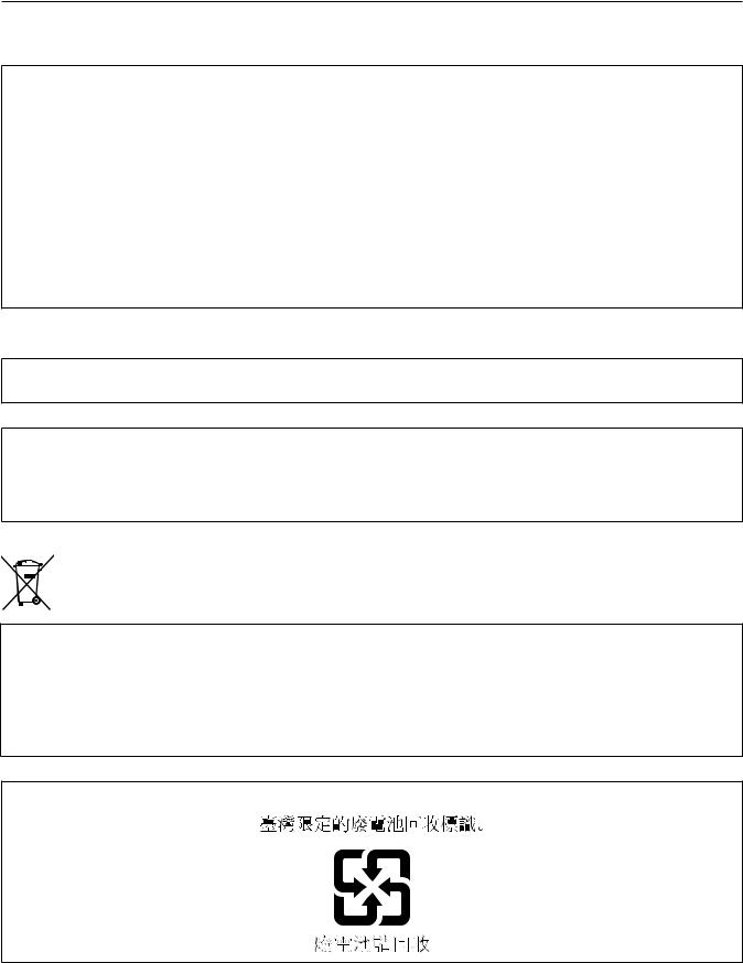
Power supply and accessory mounting section
11 |
9 |
10 |
|
8 |
|
11 12 |
13 |
2 |
|
|
|
|
|
|
3 |
|
|
14 |
|
|
|
|
|
|
|
|
|
|
4 |
|
|
|
1 |
|
|
|
|
|
|
5 |
6 |
7 |
15 |
16 |
17 18 19 |
20 |
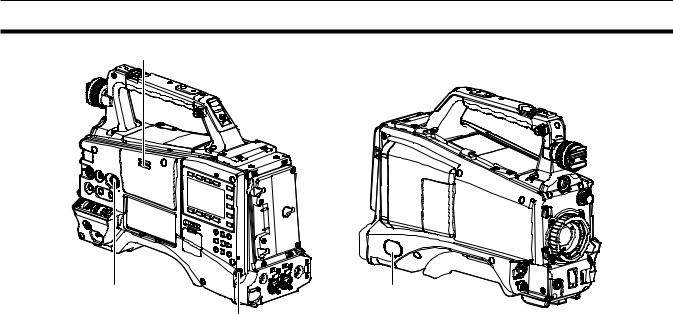
1<POWER> switch (page 48)
Switch on/off the power.
2Battery release lever (page 27)
Pull this battery release lever down to release the battery.
3Battery holder (page 27)
Mount the Anton/Bauer battery.
4 Light control switch (page 27)
5<DC IN> terminal (page 28)
This is the external DC power supply input terminal. Connect to the external DC power supply.
6<DC OUT> terminal (page 40)
This is the DC 12 V output terminal. It provides a maximum current of 1.5 A.
@@NOTE
tt When connecting external equipment to this terminal, first fully check the polarities of the connection. Failure to do so may result in a malfunction.
7<REMOTE> terminal (pages 171, 173)
Connect the remote control unit AJ RC10G (optional) to remote-control some functions. For details, refer to “Connecting to the remote control unit (AJ RC10G)” (page 171).
Connect the extension control unit AG EC4G (optional) to remote-control some functions. For details, refer to “Connecting to the extension control unit (AG EC4G)” (page 173).
8Light output terminal
Connect the Ultralight 2 of Anton/Bauer (optional) or an equivalent video light of 50 W or under.
The battery charge level drops sharply when the light is illuminated. When using the light, using a battery of 90 Wh or more is recommended.
9Cable holders
Used for clamping the light and microphone cables in place.
10Accessory mounting holes
Attach accessories. Use only for the purpose of attaching accessories. ffMounting hole size
-- 1/4 20 UNC (screw length 10 mm or shorter) -- 3/8 16 UNC (screw length 10 mm or shorter)
11Shoulder strap attachment fitting (page 38)
Attach the shoulder strap.
12Light shoe
Attach the video light. Mounting hole size
ff1/4 20 UNC (screw length 6 mm or shorter)
13Viewfinder left-right positioning ring
To adjust the left/right position of the viewfinder, loosen this ring, and slide the viewfinder to the left or right to adjust it to an easy-to-view position. Tighten the ring to clamp the viewfinder in place after adjusting the viewfinder.
14<VF> terminal
Attach the viewfinder AG CVF15G (optional), etc.
15Lens cable/microphone cable clamp (page 30)
Used for securing the lens and microphone cables.
– 15 –

Chapter 2 Description of parts — Power supply and accessory mounting section
16<LENS> terminal (page 30)
Connect the lens connection cable. For a detailed description of the lens used, refer to the Operating Instructions for the lens.
17Tripod mount (page 38)
Attach the tripod adaptor SHAN-TM700 (optional) when mounting the camera on the tripod.
18Lens mount (2/3 type bayonet) (page 30)
Mount the lens.
19Lens lever (page 30)
After mounting the lens to the lens mount, tighten the lever to secure the lens.
20Mount cap (page 30)
Raise the lens lever to remove the cap. Replace the cap when the lens is not mounted.
– 16 –
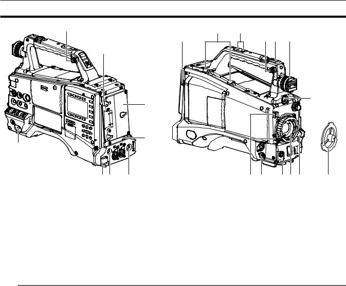
Chapter 2 Description of parts — Audio (input) function section
Audio (input) function section
6
2
4
|
|
|
|
|
|
|
|
|
|
|
|
|
5 |
|
|
|
|
|
|
|
|
|
|
|
|
|
|
|
|
|
|
|
|
|
|
|
|
|
|
|
|
1 |
3 |
|
||||
|
|
|
|
|
||
1<MIC IN> terminal (page 36)
Connect the microphone (optional).
ffThe phantom microphone can also be used. To use this, set [ON] in the main menu → [AUDIO SETUP] → [INPUT SETTING] → [FRONT MIC POWER]. When it is set to [ON] and a microphone is not connected, low frequency noise may occur. This is not a problem when a microphone is connected.
2<F.AUDIO LEVEL> dial (page 61)
Adjust the recording level of audio channels 1 to 4.
ffSetting the audio level adjustment method to [MANU] on the [AUD02:INPUT] screen of SmartUI allows you to adjust the audio level of the voice channel using this dial.
ffYou can use the main menu → [AUDIO SETUP] → [RECORDING CH SETTING] → [FRONT VR CH1], [FRONT VR CH2], [FRONT VR CH3], and [FRONT VR CH4] to set the controls so that this operation can be done from any input terminal.
3<AUDIO IN CH1/3>, <AUDIO IN CH2/4> terminal (page 37)
Connect the audio equipment or the microphone.
4<LINE>/<MIC> switch (pages 37, 200)
Switch audio input signals connected to the <AUDIO IN CH1/3>/<AUDIO IN CH2/4> terminal. <LINE>: Select when audio equipment is connected by the line input.
<MIC>: Select when the external microphone is connected.
5Microphone input power switch (page 200)
Switch to supply power to the microphones connected to <AUDIO IN CH1/3> and <AUDIO IN CH2/4> terminals. <+48V>: Supplies +48 V power to the microphone.
<OFF>: Does not supply power to the microphone.
@@NOTE
tt When microphone input <+48V> is set and microphones are not connected to the <AUDIO IN CH1/3> and <AUDIO IN CH2/4> terminals, lowfrequency noise may occur. This is not a problem when a microphone is connected.
6Wireless slot (page 36)
Mount the UniSlot wireless microphone receiver (optional).
– 17 –
Chapter 2 Description of parts — Audio (output) function section
Audio (output) function section
2
1 |
4 |
3
1<MONITOR> dial
Adjust the volume of the speaker and earphones.
2Internal speaker
During recording, EE audio can be monitored, and during playback, playback audio can be monitored. Audio from the speaker automatically disappears when earphones are connected to the <PHONES> terminal.
3<PHONES> terminal
This is the connecting terminal for audio monitor earphones (stereo mini-jack).
4<AUDIO OUT> terminal(page 148)
Output audio signals recorded on audio channel 1/2 or 3/4. ffSelect the output signal on the [AUD03:MONI] screen of SmartUI.
– 18 –
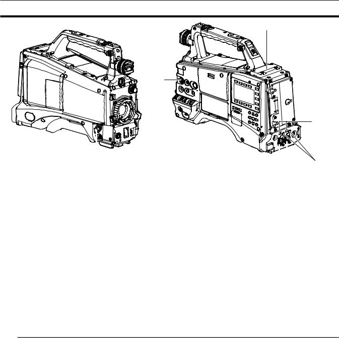
Chapter 2 Description of parts — Shooting and recording/playback functions section
Shooting and recording/playback functions section
Shooting and recording (camera unit)
1 |
|
|
|
|
2 |
3 |
4 |
5 6 7 8 |
9 |
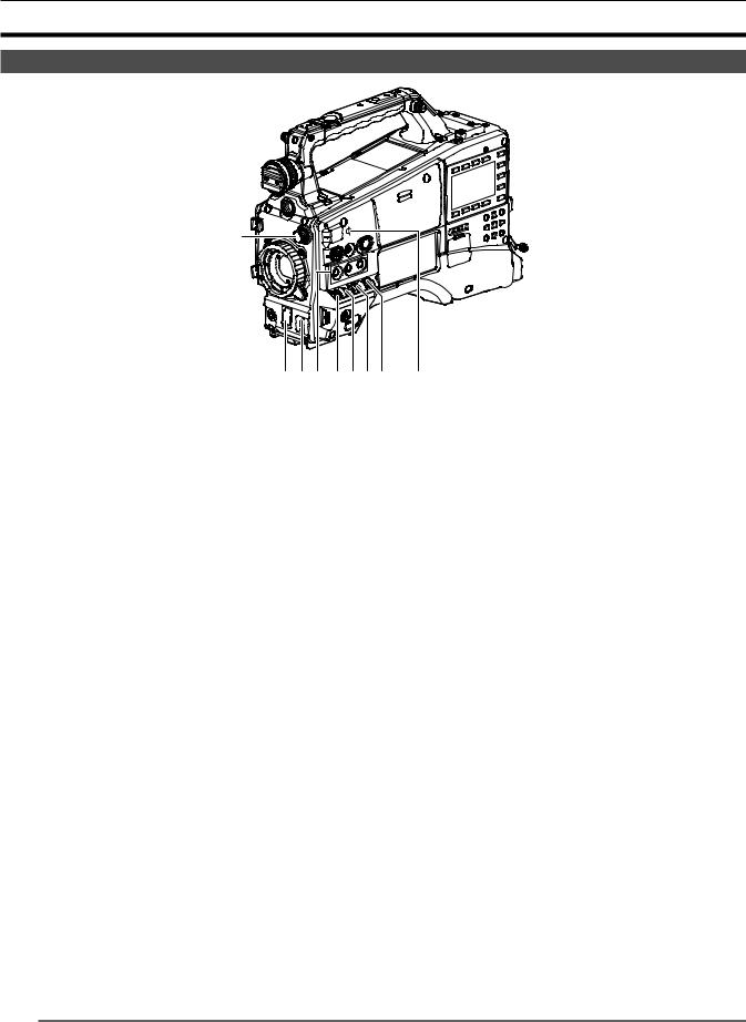
1<ND FILTER> dial (page 49)
Select the filter to suit the brightness of the subject. <1><CLEAR>: Does not use the ND filter.
<2><1/4ND>: Reduce the amount of light entering the MOS sensor to 1/4. <3><1/16ND>: Reduce the amount of light entering the MOS sensor to 1/16. <4><1/64ND>: Reduce the amount of light entering the MOS sensor to 1/64.
2<SHUTTER> switch (page 57)
This is the electronic shutter switch. <OFF>: Disables the electronic shutter. <ON>: Enables the electronic shutter.
<SEL>: Changes the speed of the electronic shutter.
This switch is the spring switch. Each turn towards the <SEL> side alters the shutter speed.
3<AUTO W/B BAL> switch (page 54)
<AWB>: Adjusts white balance automatically. When this switch is operated with the <WHITE BAL> switch on the side set to the <A> or <B> position, white balance is adjusted in several seconds and the adjusted value is stored in memory. When the <WHITE BAL> switch is at the <PRST> position, the value can be changed to the preset color temperature and user-specified variable value by setting the <AUTO W/B BAL> switch towards the <AWB> side, and setting it once again towards the <AWB> side while the color temperature is displayed.
<ABB>: Adjusts black balance automatically.
4USER (<USER MAIN>/<USER1>/<USER2> button) (page 60)
Assign user-selected functions to each button. Pressing each button performs the assigned function.
5<DISP/MODE CHK> switch (page 99)
This is the spring switch to check the status of the shooting, etc.
ffPush this towards the <OFF> side to clear all displays except viewfinder operation status and frame displays such as the area display, and the counter, marker, and safety zone displays.
ffPush this towards the <CHK> side to display in the viewfinder the setting status for all shooting functions, the list of functions assigned to the USER button, etc. while on stand-by or while shooting. Pushing it to the <CHK> side again while information is displayed switches the display to the next information page. The mode check information display disappears after approximately three seconds.
6<GAIN> switch (page 54)
Switch the video amplifier gain according to the brightness of the subject to shoot.
ffThe gain settings for the <L>/<M>/<H> positions can be changed using main menu → [SW MODE] → [LOW GAIN], [MID GAIN], and [HIGH GAIN]. ffFactory settings are L=0 dB, M=6 dB, and H=12 dB.
7<OUTPUT>/<AUTO KNEE> selector switch
Select the video signals output to the memory, viewfinder and video monitor from the camera unit.
<CAM>/<ON>: Video captured with the camera is output and the auto knee function is activated. Instead of the auto knee function, the dynamic range stretcher (DRS) function can be assigned.
<CAM>/<OFF>: Video captured with the camera is output and the auto knee function is not activated. The knee point is fixed to the level set by menu operations.
<BARS>/<OFF>: Color bars signal is output. The auto knee function is not activated.
@@NOTE
tt Auto knee function
When you adjust the levels to shoot people or scenery, etc. against a strongly lit background, the background will be totally whited out, and buildings and scenery in the background will be blurred. In such a case, the auto knee function reproduces the background clearly.
The auto knee function is effective when shooting the following scenes:
-The subject is a person positioned in the shade under a clear sky.
-When shooting people in a vehicle or building as well as the background visible through a window at the same time.
– 19 –

Chapter 2 Description of parts — Shooting and recording/playback functions section
- The subject is a high-contrast scene.
8<WHITE BAL> switch (pages 54, 55)
Select the method for adjustment of the white balance.
<PRST>: Set the switch to this position when you have no time or are otherwise unable to adjust the white balance. ffThe factory setting is 3200 K.
ffThe color temperature can be changed successively to 3200 K, 5600 K, and the user-specified variable value by setting the main menu → [SW MODE] → [W.BAL PRESET], or by pushing the <AUTO W/B BAL> switch towards the <AWB> side, and pushing the <AUTO W/B BAL> switch towards the <AWB> side again while the color temperature is displayed. The variable value can be set with the jog dial button. (page 55)
<A>/<B>: Pushing the <AUTO W/B BAL> switch towards the <AWB> side adjusts the white balance automatically and saves the adjusted value to <A> or <B>.
ffSelecting [Bch] from the main menu → [SW MODE] → [ATW] allows you to assign auto tracking white balance (ATW) function to <B>. (page 55)
9Focal plane index < >
>
Indicate the focal plane of the MOS sensor.
It provides a reference for measuring the accurate focal distance from the subject.
Shooting and recording/playback functions section (recording unit)
|
1 |
|
|
|
|
|
|
|
|
|
|
|
2 |
|
|
|
|
|
|
|
|
|
|
|
24 |
|
|
|
|
|
|
|
|
|
|
|
|
|
3 |
|
6 |
|
|
|
|
|
|
|
|
|
|
4 |
|
|
|
|
|
|
|
|
|
|
|
|
|
|
|
|
|
|
|
|
|
|
|
|
|
5 |
7 |
8 |
|
|
|
|
|
|
|
|
|
|
|
|
|
|
|
|
|
|
|
|
|
||
|
|
|
|
|
|
|
|
11 |
|
|
|
|
|
|
|
|
HOLD |
|
COUNTER |
RESET MONITOR SEL |
|
LIGHT |
23 |
||
|
|
|
|
TC |
NDF SLAVE P -REC |
|
CAM |
|||||
|
|
|
|
|
|
22 |
||||||
|
9 |
10 |
|
E |
|
F |
|
|
|
0 |
AUDIO |
|
|
|
|
|
|
|
-30 |
SETUP |
21 |
||||
|
|
|
12 |
MEDIA |
CH1 |
|
|
|
-10 |
|
|
|
|
|
|
|
|
|
A |
|
|
-20 |
|
|
|
|
|
|
BATT |
CH2 |
|
|
|
dB |
HOME |
20 |
||
|
|
|
13 |
E |
|
F |
|
1 2 |
|
|
||
|
|
|
14 |
/REW |
STOP |
FF/ |
PLAY/PAUSE |
|
|
19 |
||
|
|
|
|
KEY LOCK |
|
THUMBNAIL |
|
|
|
|||
|
|
|
15 |
|
|
|
|
|
18 |
|||
|
|
|
|
|
|
|
SET |
TOP |
SHIFT |
|||
|
|
|
|
|
|
|
|
EXIT |
MULTI SEL |
MENU |
|
|
|
|
|
|
|
|
|
|
|
|
|
||
|
|
|
|
|
|
|
|
CANCEL |
BOTTOM |
|
|
|
|
|
|
|
16 |
17 |
|
|
|
|
|
|
|
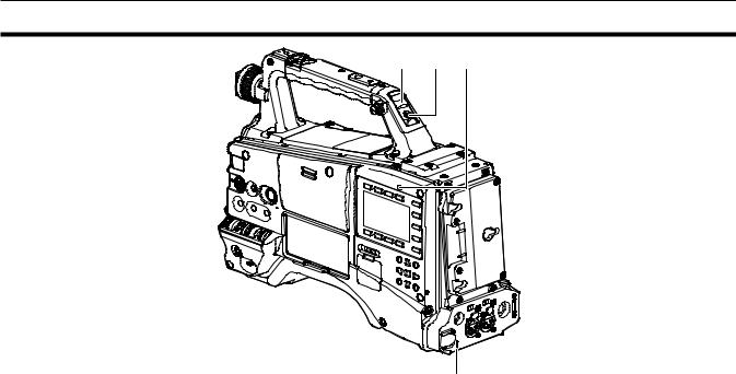
1<REC> button (page 49)
Press this button to start recording. Press it again to stop recording. This button has the same function as the VTR button on the lens side.
2<SDI OUT/IN (OP)> terminal (page 75)
This is the output terminal for SDI signals.
ffAttaching the HD/SD SDI input board AG YA600G (optional) allows you to input the SDI signal. (page 209)
3<MON OUT> terminal (page 75)
This is the output terminal of the video monitor. Video independent from the <SDI OUT/IN (OP)> terminal can be output. Also, you can select the HD SDI signal, the SD SDI signal that you down-converted, or the VBS signal on the [SET02:MON/HDMI FORMAT] screen of SmartUI. Crossconversion and up-conversion are not supported.
4<LAN> terminal (page 181)
Connect the LAN cable.
@@NOTE
tt For the cable to be connected to the <LAN> terminal, use the shielded cable.
5<USB2.0> terminal (sub-host) (pages 179, 180)
Mount the wireless module AJ WM30 (optional). Or, attach the USB 2.0 extension cable connecting the body and the 4G/LTE USB modem (optional).
6<FOCUS ASSIST> button (page 52)
Switch on/off the focus assist function.
7Busy (active status indication) lamp (page 84)
Indicate the active status of the SD memory card, and is illuminated when the card is active.
– 20 –
Chapter 2 Description of parts — Shooting and recording/playback functions section
@@NOTE
tt Do not remove or insert the card while the lamp is lit. Doing so may damage the SD memory card.
8SD memory card slot (page 83)
This is the insertion slot for the SD memory card (optional). Use the SD memory card for recording/opening the setting menu and scene files for the camera, uploading metadata, or proxy recording, etc.
@@NOTE
tt Cautions when using SD memory cards
-On the camera, use SD memory cards that conform to the SD standard, SDHC standard, or the SDXC standard. When performing proxy recording, use SDHC memory cards, SDXC memory cards, or SD memory cards with the class description of class2 or higher.
-MMC (Multi Media Card) cannot be used. (Bear in mind that taking pictures may no longer be possible if you use them.)
-When using miniSD/microSD cards with the camera, always install the adaptor specially designed for miniSD/microSD cards. (The camera will not work properly if only the miniSD/microSD adaptor is installed. Make sure that the card has been inserted into the adaptor before use.)
-Use of Panasonic SD memory cards and miniSD/microSD cards is recommended. Be sure to format cards on the camera before use.
-Refer to our support desk at the following website for the latest information not included in these operating instructions. http://pro-av.panasonic.net/
-SDHC memory cards are a standard that was established in 2006 by the SD Association for large-capacity memory cards that exceed 2 GB.
-SDXC memory cards are a standard that was established in 2009 by the SD Association for large-capacity memory cards that exceed 32 GB.
9P2 memory card access LED (page 43)
Indicate the access status of recording and playback of the card inserted in the P2 memory card slot.
10P2 memory card slot (page 42)
11<MONITOR SEL> button
Switch the audio channel that is output to the speaker, the <PHONES> terminal, and the <AUDIO OUT> terminal to [CH1/2] or [CH3/4] each time you press the button. The channel display of the audio channel level meter is switched together.
When a screen other than the [HOME] screen of SmartUI is displayed, the function corresponding to each setting screen is performed.
12<FF/)> button
Press this button during a pause to perform fast playback. Press this button during playback to perform 4x speed playback.
If it is pressed with playback paused, the clip being played back is paused at the start point of the next clip (cued state).
When a screen other than the [HOME] screen of SmartUI is displayed, the function corresponding to each setting screen is performed.
13<STOP> button
Press this button to stop playback.
Press this button when you stop interval recording or one-shot recording, or when you end combining to the clip of one-clip recording. When a screen other than the [HOME] screen of SmartUI is displayed, the function corresponding to each setting screen is performed.
14<%/REW> button
Press this button during a pause to perform fast-reverse playback. Press this button during playback to perform 4x speed reverse playback.
If it is pressed with playback paused, the clip being played back is paused at its start point (cued state).
When a screen other than the [HOME] screen of SmartUI is displayed, the function corresponding to each setting screen is performed.
15<KEY LOCK> switch (page 145)
Disable button operations related to SmartUI and thumbnail operations. However, <LIGHT> button operation is available.
16<USB2.0> terminal (device) (page 163)
17<USB2.0> terminal (host) (page 163)
Connect the USB 2.0 cable.
Setting to [ON] using main menu → [NETWORK SETUP] → [USB MODE] allows you to transfer data using USB 2.0. In this state, recording/playback and clip operations on the camera are limited.
18<PLAY/PAUSE> button
Press this button to view playback image. Press it during playback to pause playback.
When a screen other than the [HOME] screen of SmartUI is displayed, the function corresponding to each setting screen is performed.
19<HOME> button (page 145)
Display the [HOME] screen on SmartUI.
20<SETUP> button (page 150)
Display the [SETUP] screen on SmartUI.
21<AUDIO> button (page 148)
Display the [AUDIO] screen on SmartUI.
22<CAM> button (page 148)
Display the [CAMERA] screen on SmartUI.
23<LIGHT> button
Control lighting of SmartUI. Each press turns the light of the SmartUI on and off.
24<HDMI> terminal (page 75)
This is the output terminal of the video for monitor.
– 21 –

Chapter 2 Description of parts — Menu operation section and thumbnail operation section
Menu operation section and thumbnail operation section
|
|
|
|
3 |
|
|
|
|
|
|
|
|
|
|
|
|
|
|
|
||
|
|
|
|
4 |
5 |
6 |
7 |
|||
1 |
2 |
|||||||||
|
|
|
|
|
|
|||||
1Jog dial button (page 119)
ffWhen the setting menu is displayed, navigate through the setting menu pages to select and set items. Turning the jog dial button toward the bottom moves the cursor toward the bottom. Turning it toward the top moves the cursor toward the top. Press the jog dial button to fix the settings.
ffWhen the setting menu is not displayed, the following operation allows you to adjust the synchro scan speed. Press the <SHUTTER> switch from the <ON> position towards the <SEL> side several times to display the shutter speed in highlight and adjust using the jog dial button in synchro scan mode. (page 58)
2<MENU> button (page 119)
Press this button to display [USER MENU]. Press this button for 3 seconds or more to display the main menu. Press it again to return to the original image.
During recording, button operation is disabled.
This button functions in the same way as the <THUMBNAIL MENU> button.
3<THUMBNAIL> button (page 102)
Press the button to display the thumbnail screen on the viewfinder and the monitor screen connected to the camera. Button operations are disabled during recording and playback.
4<EXIT>/<CANCEL> buttons (pages 104, 119)
Restore the display to the previous state while the setting menu or property screen is displayed.
Press this button while holding down the <SHIFT> button to act as the cancel button. This is convenient, for example, for batch-canceling clip selections.
5Cursor/<SET> button (pages 104, 119)
Operate the setting menu and thumbnails.
The four triangular buttons are cursor buttons and the square button in the center is the <SET> button.
6<THUMBNAIL MENU> button
Press this button to display [USER MENU]. Press this button for three seconds or more to display the main menu. Press it again to return to the original image.
During recording, button operation is disabled.
This button functions in the same way as the <MENU> button.
@@NOTE
tt Use the cursor/<SET> button and the <EXIT>/<CANCEL> buttons to select thumbnails or operate menus. (page 104)
7<SHIFT> button (pages 104, 119)
Use this button while using other buttons at the same time. Operations with the <SHIFT> button held down are displayed in orange at the bottom of each button.
ffPress the cursor button (`/{) while holding down the <SHIFT> button.
This moves the cursor to the thumbnail of the clip at the start or the end on the thumbnail screen. ffPress the <SET> button while holding down the <SHIFT> button
This selects all clips from the previously selected clip up to the clip at the cursor position. ffPress the <EXIT>/<CANCEL> buttons while holding down the <SHIFT> button.
This works as the cancelation function.
– 22 –
Chapter 2 Description of parts — Time code section
Time code section
1
2
3 |
|
4 |
|
5 |
|
|
|
|
HOLD |
|
COUNTER |
|
RESET MONITOR SEL |
|
LIGHT |
||
TC |
NDF SLABE P -REC |
|
CAM |
|||||
|
|
|||||||
|
|
|
|
|
|
|
0 |
AUDIO |
|
|
|
|
|
|
|
-10 |
|
MEDIA |
CH1 |
|
|
|
|
|
||
A |
|
|
|
-18 |
|
|||
E |
|
F |
|
|
|
-20 |
|
|
|
|
|
|
|
-30 |
SETUP |
||
BATT |
|
CH2 |
|
|
|
|
||
|
|
|
|
|
dB |
|
||
E |
|
F |
|
|
1 |
2 |
|
|
|
|
|
|
|
|
|
|
HOME |
/REW |
|
STOP |
|
FF/ |
PLAY/PAUSE |
|
|
|
KEY LOCK |
|
|
THUMBNAIL |
|
|
|||
|
|
|
|
|
|
|||
|
|
|
|
|
|
SET |
TOP |
SHIFT |
1<GENLOCK IN> terminal (pages 95, 95)
Input reference signal terminal when the genlock is on the camera unit or when externally locking the time code.
@@NOTE
tt Supply Y signal of HD or composite signals as the input signal. However, the sub-carrier of the composite signal on the camera cannot be externally locked.
2<TC IN/OUT> terminal (page 89)
This is the input/output terminal for time code.
ffSwitch input/output using the main menu → [IN/OUT SEL] → [TC IN/OUT SEL]. ffInput the reference time code to this terminal when the time code is locked.
ffConnect to the time code input terminal of the external device when locking the time code of the external device to the time code on the camera. (page 96)
3<HOLD> button
The time data indication on the counter display area is retained for the duration that this button is held down. However, the time code generator continues to advance. Press again to release retained state.
This function is used to learn the time code or counter value of a particular recorded scene.
When a screen other than the [HOME] screen of SmartUI is displayed, the function corresponding to each setting screen is performed.
4<COUNTER> button (page 93)
Each press of the button displays the counter value, time code, user bits, and VITC user bits information on the viewfinder.
When a screen other than the [HOME] screen of SmartUI is displayed, the function corresponding to each setting screen is performed.
5<RESET> button
Reset the counter value of the time code display.
When a screen other than the [HOME] screen of SmartUI is displayed, the function corresponding to each setting screen is performed.
– 23 –
Chapter 2 Description of parts — Warning and status display section
Warning and status display section
1 |
3 |
4 |
2
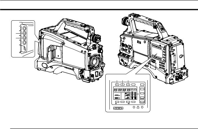
1Back tally lamp
When the back tally switch is set to <ON>, the lamp acts in the same way as the front tally lamp at the viewfinder.
2Rear tally lamp
When the back tally switch is set to <ON>, the lamp acts in the same way as the back tally lamp.
3Back tally switch
Controls the operation of the battery tally lamp and rear tally lamp. <ON>: Enables the back tally lamp and the rear tally lamp. <OFF>: Disables the back tally lamp and the rear tally lamp.
4<WARNING> lamp (page 203)
Starts flashing or is illuminated if something unusual occurs in the memory.
– 24 –
Chapter 2 Description of parts — SmartUI display ([HOME] screen)
SmartUI display ([HOME] screen)
|
|
4 |
|
5 |
|
TCG |
NDF SLAVE P -REC |
||
|
|
|
|
3 |
1 |
MEDIA |
CH1 |
A |
|
|
E |
F |
|
|
2 |
BATT |
CH2 |
|
|
|
E |
F |
1 |
2 |
|
|
|
6 |
|
1Media remaining space indicator bar
Displays the remaining free space in the P2 card using a 7-segment display.
Each segment is equivalent to three minutes, and the decreasing P2 card remaining time is indicated by the segments going out one segment at a time.
2Battery charge level indicator bar
When a battery with a digital indication (% indication) is used, all seven segments up to the F position light if the battery charge level is 70% or higher.
When the battery charge level falls below 70%, the segments go out one by one for each 10% drop.
3Audio channel level meter
One segment indicates 2 dB increment, with the smallest indication being −34 dB and the [OVER] indication displayed by r at the topmost position. Each time you press the <MONITOR SEL> button, it switches between [CH1]/[CH2], stereo, [CH3]/[CH4], and the channel display of the level meter is switched along with it. (page 148)
Channels output to the monitor audio are displayed in white dropout. When the stereo is selected, both channels are displayed in white dropout.
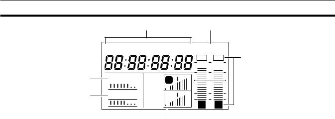
4Time code indications
Each time you press the <COUNTER> button, the display changes in the order of [COUNTER]/[CLIP] → [TCG[R]] → [UBG[R]] → [VUBG[R]] → [COUNTER]/[CLIP] (not displayed in viewfinder)* → [COUNTER]/[CLIP].
* The time code on the viewfinder is not displayed.
[COUNTER]/[CLIP]: Displays the counter in hours:minutes:seconds. When [TOTAL] is selected from the main menu → [DISPLAY SETUP] → [REC COUNTER], [COUNTER] is displayed. When [CLIP] is selected, [CLIP] is displayed.
[TCG[R]]: Displays the time code value in hours:minutes:seconds:frame. [UBG[R]]: Displays the user bits value.
[VUBG[R]]: Displays the user bits value of VITC.
[NDF]: Indicates when the time code is in the non-drop frame mode. [DF]: Indicates when the time code is in the drop frame mode. [HOLD]: Indicates when the time code generator/reader value is held.
[F RUN]: Indicates when the time code is set to advance continuously regardless of the recording operation. [R RUN]: Indicates when the time code is set to advance only during recording.
[SLAVE]: Indicates when the time code is externally locked.
5Recording mode display [REC]: Standard recording [P REC]: Pre-recording [i REC]: Interval recording [L REC]: Loop recording [S REC]: Simultaneous recording
6Status information
Audio level display: Indicates whether audio [CH1]/[CH3] or [CH2]/[CH4] audio volume and audio level are in auto adjustment mode. In the auto adjustment mode, [A] is displayed.
Audio input: Indicates audio [CH1], [CH2], [CH3], and [CH4] input settings.
When USB connected: Indicates when the main menu → [NETWORK SETUP] → [USB MODE] is set to [ON] and the device selected using [USB MODE SELECT] is connected.
ffIn the USB host mode: [USB STORAGE CONNECTED]/[USB STORAGE DISCONNECTED] ffIn the USB device mode: [USB DEVICE CONNECTED]/[USB DEVICE DISCONNECTED]
Error, card warning display: Indicates the error code when something has caused an error in the camera.
– 25 –

Chapter 3 Preparation
Before you use the camera, mount the battery and lens following the procedures in this chapter. The mounting of accessories is also described in this chapter.
Chapter 3 Preparation — Power supply
Power supply
A battery or external DC power supply can be used as the camera’s power supply.
Using batteries
Connection of the following batteries to the camera has been verified.
rr Anton/Bauer batteries
HYTRON140
DIONIC HC
rr IDX batteries
ENDURA10
rr PAG batteries
PAG L96e
@@NOTE
tt Other batteries can be used by changing [BATTERY SELECT] using the main menu → [BATTERY SETUP]. Use of batteries that are already verified as connectable to the camera is recommended.
tt Before you use a battery, charge it with a battery charger. (For details on charging, refer to each operation instructions.)
Mounting and setting battery
Using Anton/Bauer batteries
Power supply output terminal for lighting |
Release lever |
Anton/Bauer batteries
Light control switch
1 Mount the Anton/Bauer battery.
2 Insert the battery terminal and slide in the direction of the arrow.
3Set the battery type.
Select the type of battery from the main menu → [BATTERY SETUP] → [BATTERY SELECT]. For details, refer to “Setting menu basic operations” (page 119).
@@NOTE
tt The Anton/Bauer battery holder includes both a power supply output terminal for lighting and a light control switch, which are convenient when installing light. Contact Anton/Bauer, Inc. for details on lighting systems.
tt To remove the battery, keep the release lever of the battery holder completely down, slide the battery in the opposite direction of when you mounted it.
– 27 –

Chapter 3 Preparation — Power supply
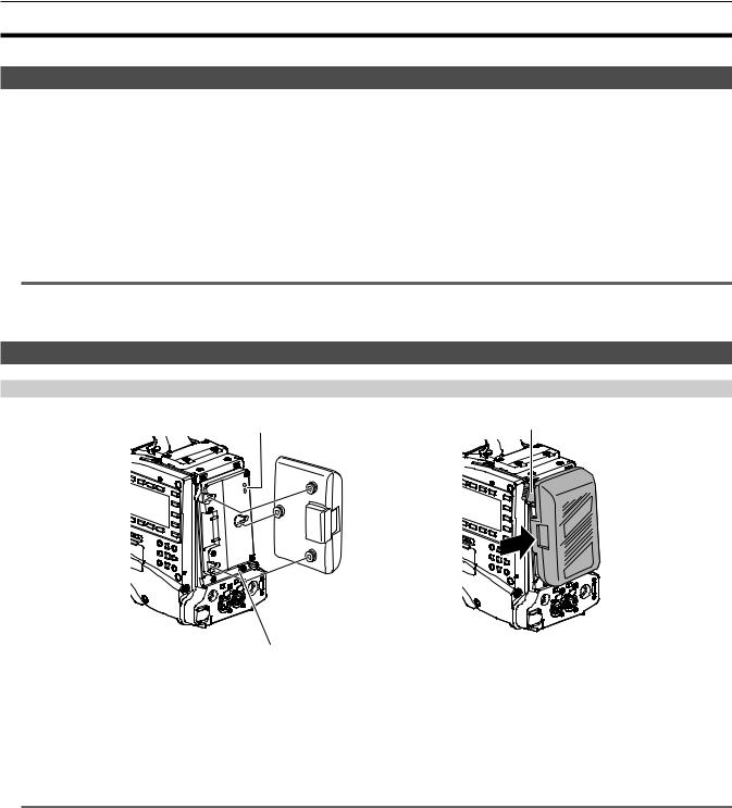
Using V-mount type batteries
Mount the V-mount type battery plate. As shown in the figure, insert and slide in the direction of the arrow.
Release lever
1 Mount the V-mount type battery plate.
2 Slide in the direction of the arrow.
3Set the battery type.
ffSelect the type of battery from the main menu → [BATTERY SETUP] → [BATTERY SELECT].
@@NOTE
tt Contact your dealer for information about the V-mount type battery plate.
tt When the V-mount type battery plate is used, % (percent) is not displayed even if batteries with a battery level indicator function are used. tt When removing the plate, remove by sliding the release lever.
tt When using a battery that is not in the [BATTERY SELECT] item, set [TYPE A], [TYPE B], or [TYPE C], and set each item according to the characteristics of the battery.
For details, refer to [BATTERY SETUP] (page 139).
Using external DC power supply
DC cable
External DC power supply
<DC IN> terminal
1 Connect the <DC IN> terminal of the camera to the external DC power supply.
2 Turn on the <POWER> switch of the external DC power supply (if the external DC power supply has a <POWER> switch).
3 Turn the camera’s <POWER> switch to <ON>.
rr External DC power supply
Connect after making sure that the output voltage of the external DC power supply is compatible with the rated voltage of the camera. Select an output amperage for the external DC power supply with a margin above the total amperage of the connected devices.
The total amperage of connected devices can be calculated with the following formula. Total power consumption ÷ voltage
When the power of the camera is turned on, inrush current is generated. Insufficient power supply when turning on the power may cause a malfunction. We recommend that you use an external DC power supply that can assure double the capacity of the total power consumption of the camera and connected devices that are turned on by interlock when the power of the camera is turned on (such as lenses, wireless microphone receivers). For the DC cable, use a dual-core shielded cord of AWG18 (nominal cross section area 0.824 mm2) or thicker.
ffMake sure of the pin alignment of the DC output terminal of the external DC power supply and the camera <DC IN> terminal, and connect the polarity correctly.
If the +12 V power supply is mistakenly connected to the GND terminal, it may cause fire or malfunction.
– 28 –

Chapter 3 Preparation — Power supply
|
|
DC IN |
|
1 |
GND |
|
2 |
NC |
|
3 |
NC |
|
4 |
+12 V |
Panasonic Parts No.: K1AA104H0038
Manufacturer Parts No.: HA16RX-4P (SW1) (76) (Hirose Electric Co.)
@@NOTE
tt When both the battery and the external DC power supply are connected, the power supply from the external DC power supply has priority. The battery may be removed while using the external DC power supply.
tt When using an external DC power supply, be sure to turn the camera’s <POWER> switch to <ON> after turning on the <POWER> switch of the external DC power supply. If the operations are performed in reverse, the camera may malfunction because the external DC power supply output voltage rises too slowly.
tt When power is supplied from the <DC IN> terminal, the light circuit does not function. The light circuit can be used only when power is supplied from the Anton/Bauer battery plate.
tt When connecting the battery to the <DC IN> terminal, set the type of battery using the main menu → [BATTERY SETUP] → [EXT DC IN SELECT]. In this case, the remaining battery level is not displayed with % even when the battery has the battery level indicator function.
– 29 –
Chapter 3 Preparation — Mounting and adjusting the lens
Mounting and adjusting the lens
Mounting the lens
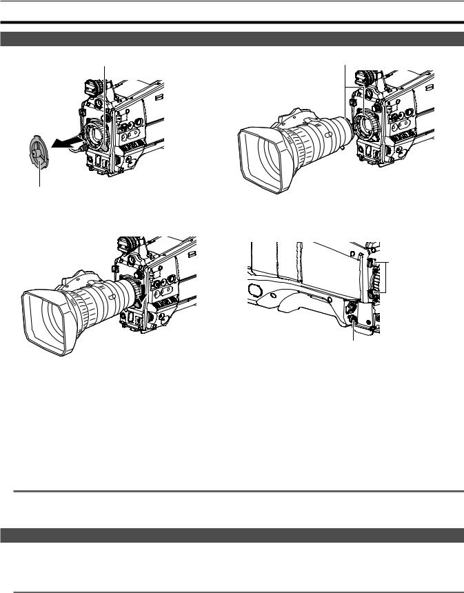
Lens lever |
Mark |
Mount cap
Fig. 1 |
Fig. 2 |
Cable clamp |
<LENS> terminal
Fig. 3 |
Fig. 4 |
|
1 Raise the lens lever and remove the mount cap. (Fig. 1)
2 Align the indentation at the top center of the lens mount with the center mark of the lens to mount the lens. (Fig. 2)
3 Lower the lens lever to firmly clamp the lens. (Fig. 3)
4 Secure the cable through the cable clamp and connect it to the <LENS> terminal. (Fig. 4)
5Perform lens flange back adjustments.
For details, refer to “Lens flange back adjustment” (page 30).
@@NOTE
tt For handling the lens, refer to the lens operating instructions.
tt For details on the current from the <LENS> terminal, refer to “Details of the connector signals” (page 215). tt When the lens is removed, install the mount cap to protect the device.
Lens flange back adjustment
If images are not clearly focused at both telephoto and wide-angle positions during zoom operations, adjust the lens flange back (distance from the lens mounting surface to the image formation surface).
Once adjusted, the lens flange back does not need to be readjusted until the lens is changed.
@@NOTE
tt Refer to the lens operating instructions for guidance on adjustment methods and positions of lens parts.
– 30 –
 Loading...