


SDTI Interface Board
AJ- 

 P
P
|
|
|
|
|
|
|
|
|
|
|
|
|
|
|
|
|
|
|
|
|
|
|
|
|
|
|
|
|
|
|
|
|
|
|
|
|
|
|
|
|
|
|
|
|
|
|
|
|
|
|
|
|
|
|
|
|
|
|
|
|
|
|
|
|
|
|
|
|
|
|
|
|
|
|
|
|
|
|
|
|
|
|
|
|
|
|
|
|
|
|
|
|
|
|
|
|
|
|
|
|
|
|
|
|
|
|
|
|
|
|
|
|
|
|
|
|
|
|
|
|
|
|
|
|
|
|
|
|
|
|
|
|
|
|
|
|
|
|
|
|
|
|
|
|
|
|
|
|
|
|
|
|
|
|
|
|
|
|
|
|
|
|
|
|
|
|
|
|
|
|
|
|
|
|
|
|
|
|
|
|
|
|
|
|
|
|
|
|
|
|
|
|
|
|
|
|
|
|
|
|
|
|
|
|
|
|
|
|
|
|
|
|
|
|
|
|
|
|
|
|
|
|
|
|
|
|
|
|
|
|
|
|
|
|
|
|
|
|
|
|
|
|
|
|
|
|
|
|
|
|
|
|
|
|
|
|
|
|
|
|
|
|
|
|
|
|
|
|
|
|
|
|
|
|
|
|
|
|
|
|
|
|
|
|
|
|
|
|
|
|
|
|
|
|
|
|
|
|
|
|
|
|
|
|
|
|
|
|
|
|
|
|
|
|
|
|
|
|
|
|
|
|
|
|
|
|
|
|
|
|
|
|
|
|
|
|
|
|
|
|
|
|
|
|
|
|
|
|
|
|
|
|
|
|
|
|
|
|
|
|
|
|
|
|
|
|
|
|
|
|
|
|
|
|
|
|
|
|
|
|
|
|
|
|
|
|
|
|
|
|
VQT8801 |
F0400T50 @ |
|||||||||||||||||||||
Contents |
|
Introduction .......................................................................................................... |
2 |
Before installation ................................................................................................ |
2 |
Connector section................................................................................................ |
2 |
Installation ............................................................................................................ |
3 |
Precautions for SDTI use..................................................................................... |
7 |
Specifications ....................................................................................................... |
7 |
Introduction |
|
This product is an SDTI interface board designed for use in the AJ-DE77, AJ-DE77H and AJDE77D models using Ver 3.0 or later of the Quick Cutter application.
Installation of this product in the AJ-DE77, AJ-DE77H or AJ-DE77D enables digital data using the SDTI format*1 (digital data compression interface) to be input and output.
CAUTION :
TO REDUCE THE RISK OF FIRE OR SHOCK HAZARD, REFER INSTALLATION OF THIS BOARD TO QUALIFIED SERVICE PERSONNEL.
*1 : SDTI (serial data transport interface) complies with the SMPTE 305M standard. The data stream format complies with the SMPTE 321M standard.
Before installation
Check that the following items have been packed together with the board.
Note that as the SDTI board is compatible with both NTSC and PAL, both NTSC and PAL ROMs have also been included with the board.
CONTENTS |
PIECES |
CONTENTS |
PIECES |
SDTI board |
1 |
TRV_IF board (VEP83392B) |
1 |
ROM for NTSC (VSI3385) |
1 |
Coaxial cable (black) |
1 |
ROM for NTSC (VSI3386) |
1 |
Coaxial cable (red) |
1 |
ROM for NTSC (VSI3387) |
1 |
Coaxial cable (yellow) |
1 |
ROM for PAL (VSI3388) |
1 |
SDTI terminal board |
1 |
ROM for PAL (VSI3389) |
1 |
Blank panel |
1 |
ROM for PAL (VSI3390) |
1 |
Installation guide (what you are reading) |
1 |
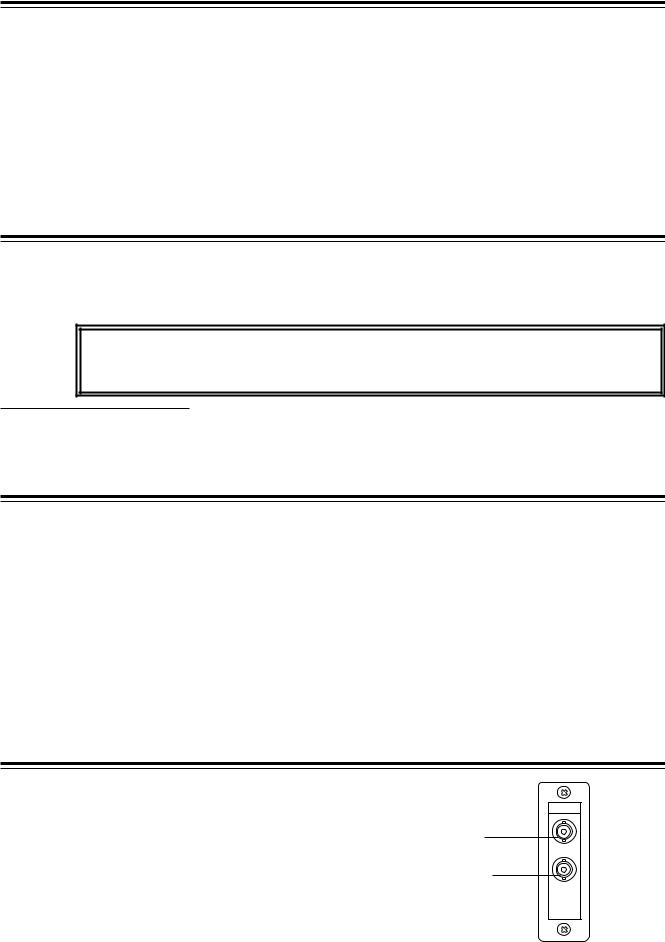
Connector section
1 SDTI dedicated serial digital input connector (BNC x 1) 2 SDTI dedicated serial digital output connector (BNC x 1)
SDTI
IN
1 Used exclusively for SDTI input signals
OUT
2 Used exclusively for SDTI output signals
-2-

Installation
Check that the power of the AJ-DE77, AJ-DE77H or AJ-DE77D (hereafter referred to as the “Quick Cutter” ) is OFF.
Screws (x4)
Remove the four screws securing the top panel of the Quick Cutter, then remove the panel.
Remove the 12 screws securing the two side panels of the Quick Cutter, then remove the panels.
Remove the four screws securing the blank panel, then remove the blank panel from the unit. (Remove the two screws in the case of the AJ-DE77D.)
Remove the seven screws securing the jack panel, then remove the jack panel from the unit.
(It cannot be completely detached because its cable remains connected.)
Screws (x6 for each side panel)
Enlarged view
Before installation |
Blank panel |
SDI
IN
Enlarged view
OUT
AJ-DE77 |
AJ-DE77D |
AJ-DE77H |
|
While referring to the figure on the right, first disassemble the accessory terminal board, and then use two screws to secure the board to the right side of the jack panel and two screws to secure the blank panel on the left side.
(In the case of the AJ-DE77D, the blank panel is not attached because the SDI terminal board is already in place on the left side.)
After installation, the panels should appear as shown in the figure below.
Connect the red coaxial cable provided with the board to the SDTI terminal board OUT and the black coaxial cable to the SDTI terminal board IN.
Screws (x7)
Jack panel
(AJ-DE77 or AJ-DE77H)
After installation |
Blank panel |
|
SDTI |
SDI |
SDTI |
IN |
IN |
IN |
OUT |
OUT |
OUT |
AJ-DE77 |
AJ-DE77D |
AJ-DE77H |
|
-3-
 Loading...