


Operating Instructions
Model No.
Model No.
Model No.
Model No.
Camera Control Unit
AK-UCU600P AK-UCU600PS AK-UCU600E AK-UCU600ES
Please carefully read this manual, and save this manual for future use. Before using this product, be sure to read “Read this first!” (pages 2 to 6).
PJ 
 PSJ
PSJ 
 EJ
EJ 
 ESJ
ESJ
W0318TY0 -FJ
ENGLISH
DVQP1734ZA
Read this first!
Read this first!
CAUTION |
RISK OF ELECTRIC SHOCK |
DO NOT OPEN |
CAUTION: TO REDUCE THE RISK OF ELECTRIC SHOCK, |
DO NOT REMOVE COVER (OR BACK). |
NO USER-SERVICEABLE PARTS INSIDE. |
REFER TO SERVICING TO QUALIFIED SERVICE PERSONNEL. |
The lightning flash with arrowhead symbol, within an equilateral triangle, is intended to alert the user to the presence of uninsulated “dangerous voltage” within the product’s enclosure that may be of sufficient magnitude to constitute a risk of electric shock to persons.
The exclamation point within an equilateral triangle is intended to alert the user to the presence of important operating and maintenance (servicing) instructions in the literature accompanying the appliance.
CAUTION:
To reduce the risk of fire or electric shock and annoying interference, use the recommended accessories only.
CAUTION:
In order to maintain adequate ventilation, do not install or place this unit in a bookcase, built-in cabinet or any other confined space. To prevent risk of electric shock or fire hazard due to overheating, ensure that curtains and any other materials do not obstruct the ventilation.
CAUTION:
The mains plug of the power supply cord shall remain readily operable.
The AC receptacle (mains socket outlet) shall be installed near the equipment and shall be easily accessible. To completely disconnect this equipment from the AC mains, disconnect the power cord plug from the AC receptacle.
WARNING:
This equipment must be grounded.
To ensure safe operation, the three-pin plug must be inserted only into a standard three-pin power outlet which is effectively grounded through normal household wiring.
Extension cords used with the equipment must have three cores and be correctly wired to provide connection to the ground. Wrongly wired extension cords are a major cause of fatalities.
The fact that the equipment operates satisfactorily does not imply that the power outlet is grounded or that the installation is completely safe. For your safety, if you are in any doubt about the effective grounding of the power outlet, please consult aqualified electrician.
WARNING:
•To reduce the risk of fire or electric shock, do not expose this equipment to rain or moisture.
•To reduce the risk of fire or electric shock, keep this equipment away from all liquids. Use and store only in locations which are not exposed to the risk of dripping or splashing liquids, and do not place any liquid containers on top of the equipment.
WARNING:
Always keep memory cards (optional accessory) out of the reach of babies and small children.
WARNING:
Installation should only be performed by qualified installation personnel. Improper installation may result in the entire apparatus falling down and causing injury.
CAUTION:
Invisible Laser radiation is emitted from the Optical fiber connector when this product is turned on. Don’t look into directly into the Optical fiber connector of this product.
CAUTION:
This product uses a semiconductor laser system and is a Class 1 Laser Product complies with Radiation Performance Standards, 21CFR SUBCHAPTER J.
Use of controls or adjustments or performance of procedures other than those specified herein may result in hazardous radiation exposure.
Don’t make any modifications. Don’t repair by yourself.
Refer servicing to qualified personnel.
CAUTION:
•Keep the temperature inside the rack to between 0 °C to 40 °C (32 °F to 104 °F).
•Bolt the rack securely to the floor so that it will not topple over when the unit is drawn out.
CAUTION:
Naked flame sources, such as lighted candles, should not be placed on the apparatus.
CAUTION:
To reduce the risk of fire or electric shock, refer mounting of the optional interface boards to qualified service personnel.
NOTIFICATION (Canada)
CAN ICES-3 (A)/NMB-3(A)


 indicates safety information.
- 2 -
Read this first!
For AK-UCU600P, AK-UCU600PS
IMPORTANT SAFETY INSTRUCTIONS
1)Read these instructions.
2)Keep these instructions.
3)Heed all warnings.
4)Follow all instructions.
5)Do not use this apparatus near water.
6)Clean only with dry cloth.
7)Do not block any ventilation openings. Install in accordance with the manufacturer’s instructions.
8)Do not install near any heat sources such as radiators, heat registers, stoves, or other apparatus (including amplifiers) that produce heat.
9)Do not defeat the safety purpose of the polarized or grounding-type plug. A polarized plug has two blades with one wider than the other. A grounding-type plug has two blades and a third grounding prong. The wide blade or the third prong are provided for your safety. If the provided plug does not fit into your outlet, consult an electrician for replacement of the obsolete outlet.
10)Protect the power cord from being walked on or pinched particularly at plugs, convenience receptacles, and the point where they exit from the apparatus.
11)Only use attachments/accessories specified by the manufacturer.
12) Use only with the cart, stand, tripod, bracket, or table specified by the manufacturer, or sold with the apparatus. When a cart is used, use caution when moving the cart/apparatus combination to avoid
injury from tip-over.
13) Unplug this apparatus during lightning storms or when unused for long periods of time.
14)Refer all servicing to qualified service personnel. Servicing is required when the apparatus has been damaged in any way, such as power-supply cord or plug is damaged, liquid has been spilled or objects have fallen into the apparatus, the apparatus has been exposed to rain or moisture, does not operate normally, or has been dropped.
FCC NOTICE (USA)
This device complies with part 15 of the FCC Rules. Operation is subject to the following two conditions:
(1) This device may not cause harmful interference, and (2) this device must accept any interference received, including interference that may cause undesired operation.
CAUTION:
This equipment has been tested and found to comply with the limits for a class A digital device, pursuant to Part 15 of the FCC Rules. These limits are designed to provide reasonable protection against harmful interference when the equipment is operated in a commercial environment. This equipment generates, uses, and can radiate radio frequency energy and, if not installed and used in accordance with the instruction manual, may cause harmful interference to radio communications. Operation of this equipment in a residential area is likely to cause harmful interference in which case the user will be required to correct the interference at his own expense.
FCC Warning:
To assure continued FCC emission limit compliance, the user must use only shielded interface cables when connecting to external units. If DVI-D port is to be used it must be connected to PC by compatible interface cable with two ferrite cores. Also, any unauthorized changes or modifications to this equipment could void the user’s authority to operate it.


 indicates safety information.
- 3 -
Read this first!
For AK-UCU600E, AK-UCU600ES
Caution for AC Mains Lead
FOR YOUR SAFETY PLEASE READ THE FOLLOWING TEXT CAREFULLY.
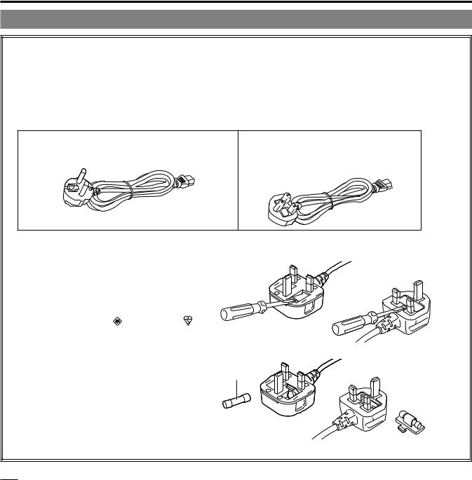
This product is equipped with 2 types of AC mains cable. One is for continental Europe, etc. and the other one is only for U.K.
Appropriate mains cable must be used in each local area, since the other type of mains cable is not suitable.
FOR CONTINENTAL EUROPE, ETC.
Not to be used in the U.K.
FOR U.K. ONLY
If the plug supplied is not suitable for your socket outlet, it should be cut off and appropriate one fitted.
FOR U.K. ONLY
This appliance is supplied with a moulded three pin mains plug for your safety and convenience.
A 13 amp fuse is fitted in this plug.
Should the fuse need to be replaced please ensure that the replacement fuse has a rating of 13 amps and that it is approved by ASTA or BSI to BS1362. Check for the ASTA mark or the BSI mark on the body of the fuse.
If the plug contains a removable fuse cover you must ensure that it is refitted when the fuse is replaced.
If you lose the fuse cover the plug must not be used until a replacement cover is obtained.
A replacement fuse cover can be purchased from
your local Panasonic Dealer
.
How to replace the fuse
1.Open the fuse compartment with a screwdriver.
or
2.Replace the fuse.
Fuse
Fuse or 


 indicates safety information.
- 4 -

Read this first!
EMC NOTICE FOR THE PURCHASER/USER OF THE APPARATUS
1. Pre-requisite conditions to achieving compliance with the above standards
<1> |
Peripheral equipment to be connected to the apparatus and special connecting cables |
|
• The purchaser/user is urged to use only equipment which has been recommended by us as peripheral equipment |
|
to be connected to the apparatus. |
|
• The purchaser/user is urged to use only the connecting cables described below. |
<2> |
For the connecting cables, use shielded cables which suit the intended purpose of the apparatus. |
•Video signal connecting cables
Use double-shielded coaxial cables, which are designed for 75-ohm type high-frequency applications, for SDI (Serial Digital Interface).
Coaxial cables, which are designed for 75-ohm type high-frequency applications, are recommended for analog video signals.
•Audio signal connecting cables
If your apparatus supports AES/EBU serial digital audio signals, use cables designed for AES/EBU.
Use shielded cables, which provide quality performance for high-frequency transmission applications, for analog audio signals.
•Other connecting cables (LAN, RS-422)
Use double shielded cables, which provide quality performance for high-frequency applications, as connecting cables.
•When connecting to the DVI signal terminal, use a cable with a ferrite core.
•If your apparatus is supplied with ferrite core(s), they must be attached on cable(s) following instructions in this manual.
2.Performance level
The performance level of the apparatus is equivalent to or better than the performance level required by these standards.
However, the apparatus may be adversely affected by interference if it is being used in an EMC environment, such as an area where strong electromagnetic fields are generated (by the presence of signal transmission towers, cellular phones, etc.). In order to minimize the adverse effects of the interference on the apparatus in cases like this, it is recommended that the following steps be taken with the apparatus being affected and with its operating environment:
1.Place the apparatus at a distance from the source of the interference.
2.Change the direction of the apparatus.
3.Change the connection method used for the apparatus.
4.Connect the apparatus to another power outlet where the power is not shared by any other appliances.
AEEE Yönetmeliğine Uygundur.
AEEE Complies with Directive of Turkey.
- 5 -
Read this first!
Manufactured by: Panasonic Corporation, Osaka, Japan
Importer’s name and address of pursuant to EU rules:
Panasonic Marketing Europe GmbH
Panasonic Testing Centre
Winsbergring 15, 22525 Hamburg, Germany
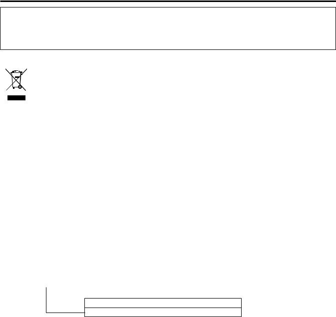
Disposal of Old Equipment
Only for European Union and countries with recycling systems
This symbol on the products, packaging, and/or accompanying documents means that used electrical and electronic products must not be mixed with general household waste.
For proper treatment, recovery and recycling of old products, please take them to applicable collection points in accordance with your national legislation.
By disposing of them correctly, you will help to save valuable resources and prevent any potential negative effects on human health and the environment. For more information about collection and recycling, please contact your local municipality, dealer or supplier.
Penalties may be applicable for incorrect disposal of this waste, in accordance with national legislation.
ІНФОРМАЦІЯ ПРО ПІДТВЕРДЖЕННЯ ВІДПОВІДНОСТІ ПРОДУКТУ
Виробник: |
Panasonic Corporation |
Панасонік Корпорейшн |
|
|
|
Адреса виробника: |
Kadoma, Osaka, Japan |
Кадома, Осака, Японія |
|
|
|
Країна походження: |
Japan |
Японія |
|
|
|
|
|
|
Імпортер: |
ТОВ “ПАНАСОНІК УКРАЇНА ЛТД” |
|
|
|
|
Адреса Імпортера: |
провулок Охтирський, будинок 7, місто Київ, 03022, Україна |
|
|
|
|
Примітки: |
|
|
Термін служби виробу |
7 років |
|
|
|
|
Дату виготовлення можна визначити за комбінацією букв і цифр серійного номера, що розташований на маркувальній табличці виробу.
Приклад: X X XXXXXXX
 Рік: остання цифра року (6 – 2016, 7 – 2017,…0 – 2020)
Місяць: А – Січень, В – Лютий… L – Грудень
- 6 -

Table of Contents |
|
Read this first!.............................................................. |
2 |
Introduction.................................................................. |
9 |
How to View This Manual................................................. |
9 |
About trademarks and registered trademarks.............. |
9 |
About copyright............................................................ |
9 |
Illustrations and screen displays featured in the |
|
manual.......................................................................... |
9 |
Abbreviations.............................................................. |
10 |
Overview........................................................................ |
11 |
Notice............................................................................. |
12 |
Personal computer requirements............................... |
12 |
Disclaimer of warranty................................................ |
12 |
Network security......................................................... |
13 |
Memory cards............................................................. |
13 |
Features......................................................................... |
14 |
Accessories.................................................................... |
15 |
Precautions for Use........................................................ |
16 |
Precautions for Installation............................................. |
17 |
Mounting the unit in a rack......................................... |
18 |
Connection................................................................. |
19 |
System configuration...................................................... |
19 |
Serial connection........................................................ |
19 |
IP connection.............................................................. |
19 |
Equipment connections.................................................. |
20 |
Parts and their functions........................................... |
21 |
Front panel 1.................................................................. |
21 |
Front panel 2.................................................................. |
22 |
Front panel 3.................................................................. |
23 |
Rear panel 1................................................................... |
24 |
Rear panel 2................................................................... |
26 |
Picture monitor (PM).................................................. |
27 |
Picture monitor displays................................................. |
27 |
Transition of displays...................................................... |
28 |
Information display......................................................... |
29 |
Warning displays........................................................ |
29 |
IRIS display................................................................ |
30 |
Status displays........................................................... |
31 |
Operation displays...................................................... |
38 |
Auto displays.............................................................. |
39 |
CCU menu................................................................... |
40 |
Menu operations............................................................. |
40 |
Displaying and hiding the menus................................... |
41 |
Basic menu operations................................................... |
42 |
Operation with menu items that have multiple |
|
setting items on one line............................................. |
44 |
Text input.................................................................... |
45 |
CCU MENU.................................................................... |
47 |
OPERATION.................................................................. |
48 |
SYSTEM MODE......................................................... |
49 |
OUT FORMAT(UHD).................................................. |
53 |
OUT FORMAT(HD).................................................... |
55 |
OUT FORMAT(UHD_HDR)........................................ |
57 |
OUT FORMAT(HD_HDR)........................................... |
59 |
SETTING(1/2)............................................................ |
60 |
SETTING(2/2)............................................................ |
61 |
HD PHASE................................................................. |
62 |
SD PHASE................................................................. |
62 |
BAR ID....................................................................... |
67 |
SELECT RETURN...................................................... |
68 |
MONITOR................................................................... |
69 |
AUDIO............................................................................ |
70 |
MIC OUT.................................................................... |
70 |
CCU INTERCOM TALK.............................................. |
71 |
CCU INTERCOM RECEIVE....................................... |
71 |
STBY INTERCOM...................................................... |
72 |
COMMUNICATION..................................................... |
72 |
INTERCOM1.............................................................. |
73 |
INTERCOM2.............................................................. |
74 |
PGM........................................................................... |
75 |
MAINTENANCE............................................................. |
76 |
START UP.................................................................. |
77 |
SETUP........................................................................ |
77 |
AUX............................................................................ |
79 |
ANALOG GAIN........................................................... |
80 |
ND/CC NAME(1/2)..................................................... |
80 |
ND/CC NAME(2/2)..................................................... |
81 |
NETWORK................................................................. |
82 |
VERSION................................................................... |
82 |
PM VIEW SETTING(1/2)............................................ |
83 |
PM VIEW SETTING(2/2)............................................ |
84 |
PM OPERATION STATUS.......................................... |
85 |
SYSTEM..................................................................... |
86 |
SD CARD................................................................... |
88 |
Saving and loading reference files and scene files.... |
89 |
Web Screen................................................................. |
90 |
Network settings............................................................. |
90 |
Software..................................................................... |
90 |
Using Easy IP Setup Software to set the unit’s |
|
settings....................................................................... |
90 |
Installing the plug-in viewer software......................... |
92 |
Displaying the web screen............................................. |
93 |
Notice regarding the Web screen............................... |
93 |
Displaying the web screen using a personal |
|
computer.................................................................... |
93 |
Switching the [Live] screen or [Setup] screen............ |
95 |
[Live] screen................................................................... |
96 |
Parts and their functions ([Live] screen)..................... |
97 |
[Setup] screen.............................................................. |
100 |
Logging into the [Setup] screen................................ |
100 |
Parts and their functions ([Setup] screen)................ |
101 |
[Basic] screen........................................................... |
102 |
[Image] screen.......................................................... |
103 |
[User mng.] screen................................................... |
110 |
[Network] screen...................................................... |
112 |
[Maintenance] screen............................................... |
116 |
Troubleshooting....................................................... |
118 |
Operation...................................................................... |
118 |
IP Images..................................................................... |
120 |
Web Screen.................................................................. |
122 |
- 7 -

Table of Contents
Reference.................................................................. |
123 |
Connector pin assignment table................................... |
123 |
Front panel............................................................... |
123 |
Rear panel................................................................ |
123 |
Front panel [G/L ON] indicator specifications........... |
130 |
Appearance.................................................................. |
131 |
Specifications........................................................... |
132 |
Index.......................................................................... |
134 |
- 8 -

Introduction
Introduction
How to View This Manual
About trademarks and registered trademarks
●● Microsoft®, Windows®, Windows® 7, Windows® 8, Windows® 8.1, Windows® 10, Internet Explorer®, ActiveX® and DirectX® are either registered trademarks or trademarks of Microsoft Corporation in the United States and other countries.
●● Apple, Mac and OS X are registered trademarks of Apple Inc., in the United States and other countries.
●● Intel® and Intel® Core™ are trademarks or registered trademarks of Intel Corporation and its subsidiaries in the United States and other countries.
●● SDXC logo is a trademark of SD-3C and LLC.
●● Other names of companies or products in this manual are either registered trademarks or trademarks of their respective owners.
About copyright
Distributing, copying, disassembling, reverse compiling, reverse engineering and also exporting in violation of export laws of the software provided with this unit are expressly prohibited.
Illustrations and screen displays featured in the manual
●● What is shown in the manual’s illustrations and screen displays may differ from how it actually appears. ●● The screenshots are used in accordance with the guidelines of Microsoft Corporation.
●● Functions which can be used by Windows only are indicated using [Windows].
- 9 -

Introduction
Abbreviations
The following abbreviations are used in this manual.
●● |
Microsoft® Windows® 7 Professional SP1 32-bit/64-bit is abbreviated to “Windows 7”. |
||
●● |
Microsoft® Windows® 8 Pro 32-bit/64-bit is abbreviated to “Windows 8”. |
||
●● |
Microsoft® Windows® 8.1 Pro 32-bit/64-bit is abbreviated to “Windows 8.1”. |
||
●● |
Microsoft® Windows® 10 Pro 32-bit/64-bit is abbreviated to “Windows 10”. |
||
●● |
Windows® Internet Explorer® 8.0, Windows® Internet Explorer® 9.0, Windows® Internet Explorer® 10.0 and Windows® Internet |
||
|
Explorer® 11.0 are abbreviated to “Internet Explorer”. |
||
●● |
The term memory card will be used below as a generic term for both SD, SDHC and SDXC memory cards. SD, SDHC or SDXC |
||
|
will be used in descriptions that refer to only one of the two card types. |
||
●● |
4K studio camera is referred to as a camera in this manual. |
||
●● |
Camera control unit is referred to as a CCU in this manual. |
||
●● |
Remote operation panel is referred to as an ROP in this manual. |
||
●● |
Master setup unit is referred to as an MSU in this manual. |
||
For the purposes of this manual, the model numbers of the units are given as listed in the table below. |
|||
|
|
|
|
|
Model number of unit |
Model number given in manual |
|
|
AK-UC4000G |
AK-UC4000 |
|
|
|
|
|
|
AK-UC4000GS |
|
|
|
|
|
|
|
|
|
|
|
AK-HRP1000G |
AK-HRP1000 |
|
|
|
|
|
|
AK-HRP1005G |
AK-HRP1005 |
|
|
|
|
|
|
AK-UCU600P |
|
|
|
|
|
|
|
AK-UCU600PS |
AK-UCU600 |
|
|
|
|
|
|
AK-UCU600E |
|
|
|
|
|
|
|
AK-UCU600ES |
|
|
|
|
|
|
|
AK-MSU1000G |
AK-MSU1000 |
|
- 10 -
Introduction
Overview
This camera control unit (CCU) is designed to be used with the 4K studio camera (AK-UC4000; sold separately).
Connect it to the 4K studio camera (hereinafter referred to as the camera) with an optical fiber multi cable (sold separately). You can use the unit to input and output the video signals of various formats.*1
The unit supports 12G/6G/3G-HD/HD-SDI outputs, analog composite outputs, HD/SD-SDI return inputs, VBS return inputs, and prompter inputs (HD-SDI, analog composite).
The unit is equipped with an HD-TRUNK/TICO output, LAN-TRUNK connector*2, and TRUNK connector. Intercom calls with the camera and microphone audio output are possible.
The unit also comes with tally and other system interface inputs.
Connecting the ROP (AK-HRP1000; sold separately, AK-HRP1005; sold separately) with a multi cable (sold separately) allows you to use the ROP to control the adjustment and setting of the camera and this unit.
*1: Configure the format and imaging mode settings on the camera according to the format setting of the CCU. *2: This cannot be used with UHD mode and HS mode.
- 11 -

Introduction
Notice
Personal computer requirements
Use a host computer that satisfies the following conditions.
CPU |
CPU Intel® Core™2 DUO 2.4 GHz or better is recommended |
|
Memory |
●● Windows |
|
|
1 GB or more |
|
|
(However, 2 GB or more for the 64-bit versions of Microsoft® Windows® 10, Microsoft® Windows® 8.1, |
|
|
Microsoft® Windows® 8, and Microsoft® Windows® 7) |
|
|
●● Mac |
|
|
2 GB or more |
|
Network function |
100BASE-TX |
|
|
1 port |
|
Image display function |
Resolution: 1024×768 pixels or more |
|
|
Color generation: True Color 24-bit or better |
|
Supported operating |
●● Windows |
|
systems and Web browser |
•• Microsoft® Windows® 10 Pro 64-bit/32-bit*1 |
|
|
•• Microsoft® Windows® 8.1 Pro 64-bit/32-bit*1 |
|
|
•• Windows® Internet Explorer® 11.0*1*3 |
|
|
•• Microsoft® Windows® 8 Pro 64-bit/32-bit*1 |
|
|
•• Windows® Internet Explorer® 10.0*1*3 |
|
|
•• Microsoft® Windows® 7 Professional SP1 64-bit/32-bit*2 |
|
|
•• Windows® Internet Explorer® 11.0/10.0/9.0/8.0*3 |
|
|
●● Mac |
|
|
•• |
OS X 10.12 |
|
|
Safari 10 |
|
•• |
OS X 10.11 |
|
|
Safari 9 |
|
•• |
OS X 10.10 |
|
|
Safari 8.0.4 |
|
•• |
OS X 10.9 |
|
|
Safari 7.0.2 |
|
•• |
OS X 10.8 |
|
|
Safari 6.1.2 |
|
|
|
*1: Use the desktop version of Internet Explorer. (Internet Explorer for Windows UI is not supported.) *2: Use is not possible in Windows® XP compatibility mode.
*3: Use is not possible with the 64-bit version of Internet Explorer®.
Disclaimer of warranty
IN NO EVENT SHALL Panasonic Corporation BE LIABLE TO ANY PARTY OR ANY PERSON, EXCEPT FOR REPLACEMENT OR REASONABLE MAINTENANCE OF THE PRODUCT, FOR THE CASES, INCLUDING BUT NOT LIMITED TO BELOW:
●● ANY DAMAGE AND LOSS, INCLUDING WITHOUT LIMITATION, DIRECT OR INDIRECT, SPECIAL, CONSEQUENTIAL OR EXEMPLARY, ARISING OUT OF OR RELATING TO THE PRODUCT;
●● PERSONAL INJURY OR ANY DAMAGE CAUSED BY INAPPROPRIATE USE OR NEGLIGENT OPERATION OF THE USER; ●● UNAUTHORIZED DISASSEMBLE, REPAIR OR MODIFICATION OF THE PRODUCT BY THE USER;
●● INCONVENIENCE OR ANY LOSS ARISING WHEN IMAGES ARE NOT DISPLAYED, DUE TO ANY REASON OR CAUSE INCLUDING ANY FAILURE OR PROBLEM OF THE PRODUCT;
●● ANY PROBLEM, CONSEQUENTIAL INCONVENIENCE, OR LOSS OR DAMAGE, ARISING OUT OF THE SYSTEM COMBINED
BY THE DEVICES OF THIRD PARTY;
●● ANY INCONVENIENCE, DAMAGES OR LOSSES RESULTING FROM ACCIDENTS CAUSED BY AN INADEQUATE
INSTALLATION METHOD OR ANY FACTORS OTHER THAN A DEFECT IN THE PRODUCT ITSELF; ●● LOSS OF REGISTERED DATA CAUSED BYANY FAILURE;
●● ANY DAMAGE OR CLAIMS DUE TO LOSS OR LEAKAGE OF IMAGE DATA OR SETTING DATA SAVED ON THIS UNIT OR ON A MEMORY CARD OR PERSONAL COMPUTER.
- 12 -

Introduction
Network security
This unit also has functions which are used when it is connected to a network.
Using the unit when it is connected to a network may possibly give rise to the following. ●● Leakage or disclosure of information transmitted via this unit
●● Unauthorized use of this unit by a third person with malicious intent
●● Interference or stoppage of this unit by a third person with malicious intent
It is your responsibility to take sufficient network security measures such as those described below to protect yourself against the above risks.
●● Use this unit in a network secured by a firewall, etc.
●● If this unit is used in a system with a personal computer connected, make sure that checks for and removal of computer viruses and malicious programs are implemented regularly.
Also observe the following points.
●● Do not install the unit in a location where the unit, cables, and other parts may be easily damaged.
Memory cards
Memory cards used with the unit should conform to SD, SDHC or SDXC standards.
Be sure to use the unit to format memory cards.
Memory cards with the following capacity can be used with the unit.
SD: |
2 GB |
|
|
SDHC: |
4 GB to 32 GB |
|
|
SDXC: |
64 GB |
For the latest information not described in the Operating Instructions, refer to the following website. https://pro-av.panasonic.net/
Observe the following points when using and storing this unit. ●● Avoid high temperature and humidity.
●● Avoid water droplets. ●● Avoid static electricity.
- 13 -

Introduction
Features
4K and HD format simultaneous operation possible (when using AK-UC4000)
As a standard feature, this unit incorporates 4K video (UHD) output, HD high speed video output, HD video signal output, and analog composite video signals that are available when this unit is used in combination with AK-UC4000.
BAR ID display
Characters can be displayed on the color bar signals so as to identify the output source of the images, and then output.
Prompter
As a standard feature, the unit incorporates prompter input. (HD-SDI×1, Analog composite×2)
- 14 -

Introduction
Accessories
●● After removing the product from its container, dispose of the power cable cap (if supplied) and packing materials in an appropriate manner.
Power cable |
Rack mount adapters*1……………2 |
●● for AK-UCU600P / AK-UCU600PS……………1 |
“Mounting the rack mount adapters” (see page 18) |
●● for AK-UCU600E / AK-UCU600ES……………2
*1: The screws for the rack mount adapters come attached to the unit.
- 15 -

Introduction
Precautions for Use
In addition to the safety precautions given in “Read this first!”, also observe the following instructions.
Handle carefully
●● Do not drop the product or subject it to a strong impact. Doing so may cause a failure or accident.
Avoid using the unit outdoors
●● Use the product in an ambient temperature of 0 °C to 40 °C (32 °F to 104 °F). Avoid using the product in a cold place where the temperature drops below 0 °C (32 °F) or in a hot place where the temperature rises above 40 °C (104 °F) because an extremely low or high temperature will adversely affect the internal parts.
Turn off the power before connecting or disconnecting cables
●● Before connecting or disconnecting the cables, be sure to turn the power off.
Avoid humidity and dust
●● Avoid using the product in a very humid or dusty place because a lot of humidity and dust will cause damage to the internal parts.
Cleaning
●● Turn the power off and wipe the product with a dry cloth.
●● To remove stubborn dirt, dip a cloth into a diluted solution of kitchen detergent (neutral detergent), wring it out well, and wipe the product gently. Then, wipe the product with a cloth dampened with water. Finally, wipe the product with a dry cloth.
 NOTE
NOTE
•• Avoid using benzine, paint thinners and other volatile fluids.
•• If a chemical cleaning cloth is to be used, carefully read through the precautions for its use.
Optical fiber multi cable
●● When the optical fiber connectors of the optical fiber multi cable (sold separately) become dirty, the optical signal transmission state will deteriorate. Use commercially available optical connector cleaner to clean the optical connector end faces in accordance with the instructions.
Consumable parts
●● The cooling fan is a consumable part. The replacement cycle is approximately 10 years (when used approximately 8 hours per day).
Contact your dealer to request cooling fan replacement.
Disposal of the unit
●● When the unit has reached the end of its service life and is to be disposed of, ask a qualified contractor to dispose of the unit properly in order to protect the environment.
■ Information on software used with this product
This product includes GNU General Public License (GPL) and GNU Lesser General Public License (LGPL) licensed software, and the customer is entitled to obtain, modify, or redistribute the source code for the software.
●● This product includes MIT Licensed software. ●● This product includes BSD Licensed software.
●● For details on obtaining the source codes, visit the following website. https://pro-av.panasonic.net/
However, do not contact Panasonic for questions regarding obtained source codes.
- 16 -
Introduction
Precautions for Installation
In addition to the safety precautions given in “Read this first!”, also observe the following instructions. Be sure to ask your dealer to perform the installation and connection work for the unit.
Connecting a power supply
●● Be sure to use the power cable supplied with the unit.
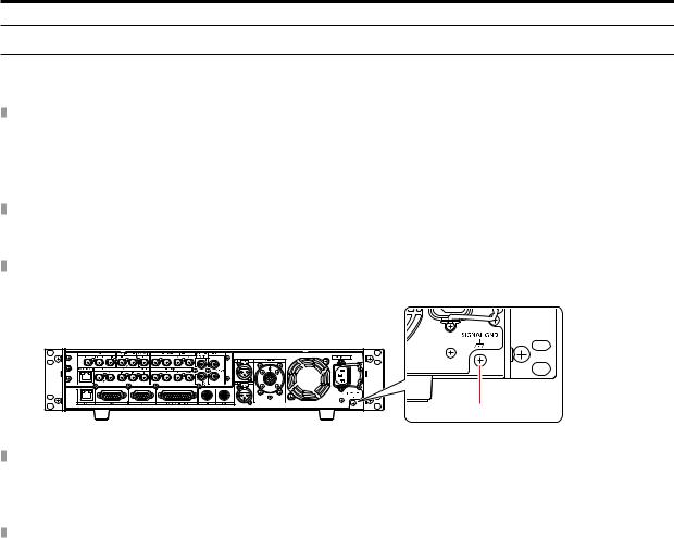
●● Connect the [SIGNAL GND] terminal on the rear of the unit to the system ground.
●● When the unit will not be used for a long time, turn off the [POWER] switch and remove the power plug from the outlet to save power.
Ground of the power plug
●● The power cable supplied with the unit has a 3-prong plug with a ground terminal. Connect it to a 3-prong outlet with a ground contact.
Grounding
●● Ground the system via the [SIGNAL GND] terminal on the unit.
A
A. [SIGNAL GND] terminal
Handle carefully
●● Dropping the unit or subjecting it to a strong impact or vibration may cause a failure or accident.
●● Do not allow any foreign objects to enter inside the unit.
Allowing water, metal items, food or drink, or other foreign objects to enter inside the unit may cause a fire or electric shock.
Installation location
●● This unit is designed for indoor use only.
●● Do not install the unit in a cold place where the temperature drops below 0 °C (32 °F) or in a hot place where the temperature rises above 40 °C (104 °F).
●● Avoid installing the unit where it will be exposed to direct sunlight or near an outlet from which hot air is blown out. ●● Installing the unit in a location with a lot of humidity, dust, or vibration may result in a failure.
- 17 -

Introduction
Mounting the unit in a rack
Mounting the rack mount adapters
1. Remove the setting legs (A) secured to the unit.
Remove them using a Phillips screwdriver.
2. Mount the supplied rack mount adapters (B).
●● Mounting screws are not supplied. Use mounting screws removed from the unit using a Phillips screwdriver. Tighten the mounting screws for rack mount adapters using a torque of 110 N·m or more.
B B
A
 A
A

 A
A  A
A
A.Setting legs
B.Rack mount adapters
Mounting the unit in a rack
●● Use the unit securely mounted in a standard 19-type rack (depth: 600 mm [23-5/8 inches] or more) compliant with EIA or JIS standards or equivalent.
●● Securely fix the unit in place using screws that are appropriate for the rack.
●● Be sure to attach a support guide for supporting (A) the rear of the unit. (Provide a support guide that is appropriate for the rack.)
A
A. Support guide
Mounting positions
In the case of the EIA standard rack |
In the case of the JIS standard rack |
|
|
|
|
76.2 mm |
50 mm |
(3 inches) |
(1-15/16 inches) |
 NOTE
NOTE
●● Do not block the ventilation holes when installing the unit.
- 18 -
Connection
Connection
System configuration
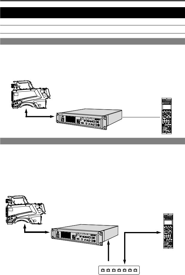
Serial connection
Use the optical fiber multi cable (sold separately) to connect the unit and camera.
Use a ROP cable to connect the unit to the ROP (AK-HRP1000 / AK-HRP1005).
For the connection procedure, see "Equipment connections."
 “Equipment connections” (see page 20)
Camera:
AK-UC4000
Optical fiber multi cable (sold separately)
ROP : AK-HRP1000 /
AK-HRP1005
Camera control unit (CCU): AK-UCU600
ROP cable (sold separately)
IP connection
Use the optical fiber multi cable (sold separately) to connect the unit and camera.
Connect the unit to the ROP (AK-HRP1000 / AK-HRP1005) via a PoE-compatible switching hub using LAN cables (straight cables: sold separately).
●● Read “Network security” before connecting the devices. ●● Use a switching hub with PoE support.
For the connection procedure, see "Equipment connections."  “Equipment connections” (see page 20)
Camera: AK-UC4000
Optical fiber multi cable (sold separately)
ROP : AK-HRP1000 /
AK-HRP1005
Camera control unit (CCU): AK-UCU600
LAN cable
(straight cable)
(sold separately)
LAN cable (straight cable) (sold separately)
PoE-compatible switching hub
- 19 -

Connection
Equipment connections
●● Before proceeding with the connections, check that the power of the unit and camera is OFF.
●● Use the optical fiber multi cable to connect the unit and camera. Connect only the AK-UC4000 camera: Do not connect any other model.
●● Use a dedicated cable to connect the unit to the ROP.
●● When the unit’s [POWER] switch is set to ON and then the camera’s power is set to ON, the camera can be controlled using the
ROP.
●● The camera statuses are shown on the picture monitor.
 “Picture monitor displays” (see page 27)
When you configure the unit’s settings by menu operations, the menu screens are displayed on the picture monitor.
 “Menu operations” (see page 40)
●● Before disconnecting the cables from the camera and ROP, turn off the camera’s power and then turn off the unit’s power.
●● When connecting the unit to the ROP using IP connection via a switching hub, use a switching hub that provides PoE support.
●● When operating multiple ROPs at the same time with the unit connected using IP connection via a switching hub, the ROP operated last will be given priority.
Camera:
AK-UC4000
PROMPT (Analog composite) |
|
UHD/HS/HD SDI OUT |
|
PROMPT (HD) |
|
Picture monitor |
|
(Analog composite) |
|
|
ROP : |
|
AK-HRP1000 / |
Personal computer |
AK-HRP1005 |
|
|
PoE-compatible |
|
switching hub |
|
ROP : |
Picture monitor |
(HD-SDI) |
|
AK-HRP1000 / |
|
AK-HRP1005 |
|
|
HD SDI OUT |
|
HD/SD-SDI RET |
- 20 -
Parts and their functions
Parts and their functions
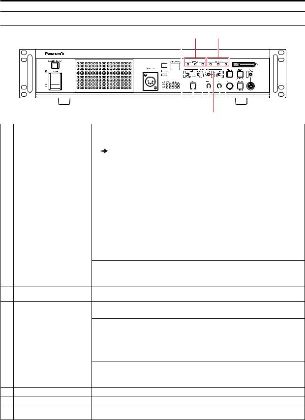
Front panel 1
3 |
5 |
4 |
6 |
|||
|
|
|
|
|
|
|
|
|
|
|
|
|
|
|
|
|
|
|
|
|
|
|
|
|
|
|
|
|
|
|
|
|
|
|
|
|
|
|
|
|
|
|
|
|
|
|
|
|
|
|
|
|
|
|
|
|
|
|
|
|
|
|
|
|
|
|
|
|
|
|
|
|
|
|
|
|
|
|
|
|
|
|
|
|
|
|
|
|
|
|
|
|
|
|
|
|
|
|
|
|
|
|
|
|
|
|
|
|
2 |
|
1 |
|
|
|
|
|
|
|
|
|
|
|
|
7 |
|||
|
|
|
|
|
|
|
|
|
|
|
|
|
|
||||||
1 |
[POWER] switch |
This is the unit’s power switch. |
|||||||||||||||||
|
|
|
|
|
|
|
Move it to the ON position to turn on the power. |
||||||||||||
|
|
|
|
|
|
|
|
|
|
|
|
|
|
ON ( |
|
|
) |
|
|
|
|
|
|
|
|
|
|
|
|
|
|
|
|
|
|
||||
|
|
|
|
|
|
|
|
|
|
|
|
|
|
OFF ( |
) |
|
|||
|
|
|
|
|
|
|
|
|
|
|
|
|
|
|
|||||
|
|
|
|
|
|
|
|
|
|
|
|
|
|
|
|
|
|
|
|
|
|
|
|
|
|
|
|
|
|
|
|
|
|
|
|
|
|
|
|
2 |
[POWER] lamp |
|
|
|
This lights when [POWER] switch is set to ON and power is supplied to the unit. |
||||||||||||||
3 |
[CAMERA POWER] button |
When you press the [CAMERA POWER] button, the unit begins supplying power to the camera. |
|||||||||||||||||
|
|
|
|
|
|
|
The color in which the button lights varies depending on the status of the camera. |
||||||||||||
|
|
|
|
|
|
|
Status displays |
|
|
|
|
|
|||||||
|
|
|
|
|
|
|
When the [CABLE CONNECTION] menu item is set to [HYBRID] |
||||||||||||
|
|
|
|
|
|
|
Lit (green) |
When the camera's power is ON, and communication between the camera |
|||||||||||
|
|
|
|
|
|
|
|
|
|
|
|
|
|
|
and CCU is possible |
||||
|
|
|
|
|
|
|
Lit (red) |
When camera was turned OFF on the camera side during standby power |
|||||||||||
|
|
|
|
|
|
|
|
|
|
|
|
|
|
|
supply |
||||
|
|
|
|
|
|
|
Flashing (red) |
When the camera can be turned ON from the unit or ROP during standby |
|||||||||||
|
|
|
|
|
|
|
|
|
|
|
|
|
|
|
power supply |
||||
|
|
|
|
|
|
|
Off |
|
|
|
|
|
|
When power is not supplied to the camera (e.g., [CABLE OPEN] status) |
|||||
|
|
|
|
|
|
|
When the [CABLE CONNECTION] menu item is set to [FIBER] |
||||||||||||
|
|
|
|
|
|
|
Lit (green) |
When communication between the camera and CCU is possible |
|||||||||||
|
|
|
|
|
|
|
Off |
|
|
|
|
|
|
When communication between the camera and CCU is not possible |
|||||
4 |
[TALLY] lamps |
|
|
|
The lamp remains lit while tally signals (R, G, YL) are input. |
||||||||||||||
|
|
|
|
|
|
|
|
|
|
|
|
A |
|
|
|
|
|
||
|
|
|
|
|
|
|
|
|
|
|
|
|
|
|
|
|
|||
|
|
|
|
|
|
|
|
|
|
|
|
B |
|
|
|
|
|
||
|
|
|
|
|
|
|
|
|
|
|
|
|
|
|
|
|
|||
|
|
|
|
|
|
|
|
|
|
|
|
C |
|
|
|
|
|
||
|
|
|
|
|
|
|
|
|
|
|
|
|
|
|
|
|
|||
|
|
|
|
|
|
|
A. |
R tally lamp |
|
|
|
|
|
||||||
|
|
|
|
|
|
|
B. |
G tally lamp |
|
|
|
|
|
||||||
|
|
|
|
|
|
|
C. |
YL tally lamp |
|
|
|
|
|
||||||
|
|
|
|
|
|
|
|
|
|
|
|
|
|
||||||
5 |
[INTERCOM] connector |
This connector is for connecting the intercom. |
|||||||||||||||||
|
|
|
|
|
|
|
This connector enables calls with the intercom line of the camera. |
||||||||||||
|
|
|
|
|
|
|
Calls can also be made with the camera when the camera’s power is OFF. |
||||||||||||
|
|
|
|
|
|
|
|
|
|
|
|
|
|
||||||
6 |
[CAMERA No.] display |
Indicates the camera number that has been assigned to the unit. |
|||||||||||||||||
7 |
[OPTICAL LEVEL] indicators |
Indicates the reception strength of optical transmission. |
|||||||||||||||||
|
|
|
|
|
|
|
●● |
[CAM] indicator |
|
|
|
|
|
||||||
|
|
|
|
|
|
|
|
|
Indicates the reception strength on the camera side. |
||||||||||
|
|
|
|
|
|
|
●● |
[CCU] indicator |
|
|
|
|
|
||||||
|
|
|
|
|
|
|
|
|
Indicates the reception strength on the CCU side. |
||||||||||
|
|
|
|
|
|
|
|
|
|
|
|
|
|
|
|
|
|
|
|
- 21 -
Parts and their functions
Front panel 2
4 |
1 |
2 |
|
|
|
|
|
|
|
|
|
|
|
|
|
|
|
|
|
|
|
|
|
|
|
|
|
|
|
|
|
|
|
|
|
|
|
|
|
|
|
|
|
|
|
|
|
|
|
|
|
|
|
|
|
|
|
|
|
|
|
|
|
|
|
|
|
|
|
|
|
|
|
|
|
|
|
|
|
|
|
|
|
|
|
|
|
|
|
|
|
|
|
|
|
8 |
9 |
|
||
|
|
|
|
|
|
3 |
|
10 |
5 |
6 |
7 |
|||||
|
|
|
|
|
|
|
|
|
|
|
|
|
|
|||
1 |
[STATUS] indicators |
Lights to indicate the unit status. |
|
|
|
|
|
|
|
|
|
|||||
|
|
|
|
●● |
[G/L ON] indicator |
|
|
|
|
|
|
|
|
|
||
|
|
|
|
|
Lights when the external sync signal is synchronized. |
|
|
|
||||||||
|
|
|
|
|
“Front panel [G/L ON] indicator specifications” (see page 130) |
|||||||||||
|
|
|
|
●● |
[FAN] indicator |
|
|
|
|
|
|
|
|
|
|
|
|
|
|
|
|
Lights when the rotation speed of the unit's cooling fan drops below the normal value. |
|||||||||||
|
|
|
|
●● |
[ALARM] indicator |
|
|
|
|
|
|
|
|
|
||
|
|
|
|
|
Lights when the unit malfunctions. |
|
|
|
|
|
|
|
|
|
||
|
|
|
|
|
|
|
|
|
|
|
|
|||||
2 |
[CABLE] indicators |
Lights to indicate the cable connection status. |
|
|
|
|
|
|
|
|||||||
|
|
|
|
●● |
[NORMAL] indicator |
|
|
|
|
|
|
|
|
|
||
|
|
|
|
|
This lights when the unit and camera are properly connected by the optical fiber multi cable. |
|||||||||||
|
|
|
|
●● |
[OPEN] indicator |
|
|
|
|
|
|
|
|
|
||
|
|
|
|
|
This lights when the unit and camera are not connected by the optical fiber multi cable. |
|||||||||||
|
|
|
|
●● |
[SHORT] indicator |
|
|
|
|
|
|
|
|
|
||
|
|
|
|
|
This lights when the cable connecting the unit and camera has been short-circuited. |
|||||||||||
3 |
[PRIV/SYSTEM] selector switch |
This switch is for selecting the party to call using the intercom. |
||||||||||||||
|
|
|
|
Switch position |
|
|
|
|
|
|
|
|
|
|
|
|
|
|
|
|
PRIV: |
For making private calls between the unit and camera side. |
|||||||||||
|
|
|
|
SYSTEM: |
For calling the intercom on the system side and camera side. |
|||||||||||
|
|
|
|
|
||||||||||||
4 |
[PRIV] indicator |
Lights when the [PRIV/SYSTEM] selector switch is set to PRIV. |
||||||||||||||
5[PROD/BOTH/ENG] selector This switch selects the party to which to speak via the intercom. switch
6 |
[MIC] switch |
This switch switches the intercom microphone ON/OFF. |
|
|
|
Switch position |
|
|
|
ON: |
The intercom microphone is turned on. |
|
|
OFF: |
The intercom microphone is turned off. |
|
|
PTT: |
The intercom microphone is on only while the switch is held down. |
|
|
|
|
7 |
[PGM] switch |
This switch mixes audio for the intercom. |
|
|
|
Switch position |
|
|
|
PGM1: |
The sound of PGM1 is mixed with the intercom sound. |
|
|
OFF: |
The sound of PGM is not mixed with the intercom sound. |
|
|
PGM2: |
The sound of PGM2 is mixed with the intercom sound. |
8[INCOM LEVEL] adjustment dial These controls are for adjusting the volume level of the sound heard through the intercom.
9[PGM LEVEL] adjustment dial This dial adjusts the volume level of the intercom's program audio mix.
10 [CALL] button |
This button calls the camera and the ROP. |
|
During calling, it lights red. |
- 22 -
Parts and their functions
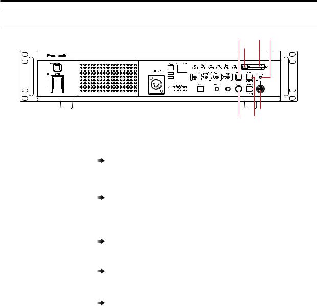
Front panel 3
1 |
6 |
4 |
7
|
5 |
2 |
3 |
1 |
[MENU] button |
When you hold down the [MENU] button, the menu screen is displayed on the picture monitor |
|
|
and the [MENU] button lights. |
|
|
If you hold down the [MENU] button while the menu is displayed, the menu closes and the [MENU] |
|
|
button turns off. |
|
|
“Menu operations” (see page 40) |
|
|
|
2 |
[SELECT] dial |
This jog dial is for menu screen operations. |
|
|
When the [SELECT] dial is turned clockwise, the cursor moves down; conversely, when it is |
|
|
turned counterclockwise, the cursor moves up. |
|
|
Press the [SELECT] dial to select the menu items. |
|
|
“Menu operations” (see page 40) |
|
|
|
3 |
[USER1] and [USER2] buttons |
These buttons are used for assigning functions. |
|
|
Function assignments are selected using [SETUP] in the CCU menu. |
|
|
The following functions are pre-assigned at the factory. |
|
|
[USER1] button: CHARA |
|
|
[USER2] button: LOCK |
|
|
“SETUP” (see page 77) |
|
|
|
4 |
[ROP FRONT/REAR] selector |
This switch switches between the [ROP] connectors on the front and rear panels. |
|
switch |
This is enabled when [MAINTENANCE] > [SETUP] > [ROP SW] is set to [SWITCH SELECT] in |
|
|
the CCU menu. |
|
|
“ROP SW” (see page 78) |
|
|
|
5 |
[ROP] connector (front) |
This connector is for connecting a ROP (sold separately). |
6 |
Memory card slot |
Insert a memory card (sold separately). |
|
|
A memory card can be used to set this unit. |
|
|
“SD CARD” (see page 88) |
|
|
|
7 |
Memory card access lamp |
This is lit while the memory card is being accessed. |
- 23 -
Parts and their functions
Rear panel 1
10 |
3 |
4 |
5 |
6 |
1 |
8 |
9 |
|
|
|
7 |
|
2 |
|
|
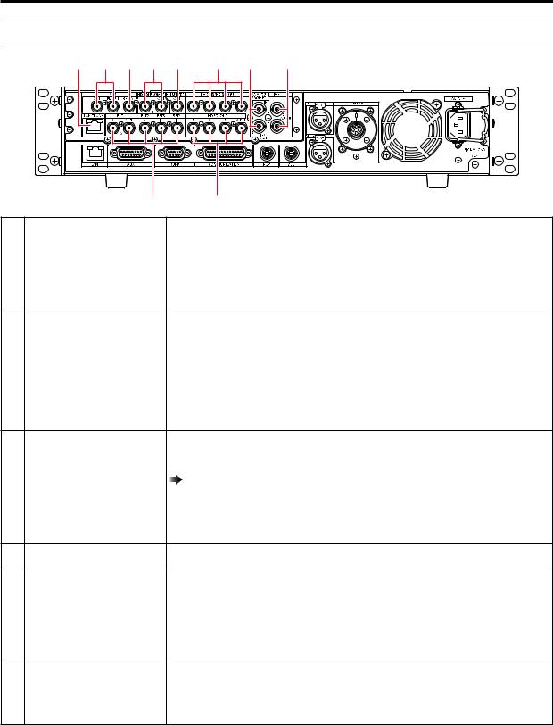
1 [UHD/HS/HD SDI OUT] |
UHD (connects to the AK-UC4000), HS and 3G-HD, HD video signal output connectors (BNC). |
connectors [1] to [4] |
Signals output can be selected from the CCU menu. |
 “OUT FORMAT(UHD)” (see page 53)
 “OUT FORMAT(HD)” (see page 55)
 “OUT FORMAT(UHD_HDR)” (see page 57)
  “OUT FORMAT(HD_HDR)” (see page 59)
2 [HD SDI OUT] connectors [5] to |
These connectors (BNC) are for outputting SDI signals in HDTV format. The 3G-HD/HD output |
[7] and [8/PM] |
mode can be selected by setting the CCU menu. |
|
SDI output from the [8/PM] connector can be switched to main line image output or picture |
|
monitor output via the CCU menu configurations or ROP control. |
 “OUT FORMAT(UHD)” (see page 53)
 “OUT FORMAT(HD)” (see page 55)
 “OUT FORMAT(UHD_HDR)” (see page 57)
  “OUT FORMAT(HD_HDR)” (see page 59)
3 |
[VBS OUT] and [VBS PM OUT] |
This connector (BNC) is for outputting analog composite signals in SDTV format. |
|
connectors |
The output from [VBS PM OUT] connector can be switched between output for this unit and |
|
|
output for the picture monitor via the CCU menu configurations. |
|
|
“SETTING(1/2)” (see page 60) |
|
|
This unit's analog composite signal is for use with a monitor. Frame sequence locking is not |
|
|
applied to the BB (black burst) synchronization signal. |
|
|
|
4 |
[VBS RET IN] connector |
This connector (BNC) is for inputting analog composite signals for return images in SDTV |
|
|
format. |
5[HD SDI PROMPT IN] and [HD These connectors (BNC) are for inputting HD-SDI prompter signals.
SDI PROMPT OUT] connectors An active through signal is output from the [HD SDI PROMPT OUT] connector.
6 |
[HD TRUNK/TICO OUT] |
This connector outputs the HD SDI TRUNK signal input or TICO to the camera. |
|
connector |
|
7 |
[RET1 IN] to [RET4 IN] and |
These connectors (BNC) are for inputting SDI signals for return images in HDTV and SDTV |
|
[RET1 OUT] connectors |
formats. |
|
|
3G, HD-SDI, and SD-SDI signals are detected automatically. |
|
|
The signal input to [RET1 IN] connector is output from the [RET1 OUT] connector as an active |
|
|
through signal. |
8[ANALOG PROMPT1 IN] and This connector (BNC) is for inputting SD analog composite signals for the prompter. [ANALOG PROMPT2 IN/OUT] It is not terminated when the unit is turned OFF.
connectors |
You can switch between "output connector for the signal input to IN" or "input connector for |
|
ANALOG PROMPT2" for the [ANALOG PROMPT2 IN/OUT] connector via menu configurations. |
|
However, the signal is not output when the unit is turned OFF. |
- 24 -

Parts and their functions
9 [REF] connectors |
These connectors (BNC) are for inputting reference signals. |
|
Black burst (BB) signals and tri-level sync signals can be input, and the type of signals input is |
|
recognized automatically.*1 |
|
When no cable is connected to the loop-through output connector (B), the connector is |
|
automatically terminated at 75 Ω. |
|
Connecting a cable to this connector releases 75 Ω termination. |
|
When a cable is connected to the loop-through output connector (B), be sure to connect the |
|
other end of the cable to a connector. |
|
|
|
A |
|
|
|
|
|
|
|
B |
|
|
|
|
|
A. Reference signal input connector |
||
|
B. Loop-through output |
||
|
*1: When the [CCU MODE] is [1080/23.98psF], input 1080/23.98psF (47.95 Hz) tri-level sync |
||
|
signals. |
||
|
For details on supported sync signals for each format, see "Front panel [G/L ON] indicator |
||
|
specifications." |
||
|
“Front panel [G/L ON] indicator specifications” (see page 130) |
||
|
|
|
|
10 [LAN TRUNK] connector |
LAN communication is carried using optical transmission between the camera and CCU. |
||
- 25 -
Parts and their functions
Rear panel 2
|
|
|
|
|
7 |
8 |
|
10 |
1 |
2 |
3 |
4 |
5 |
6 |
|
9 |
11 |
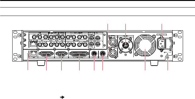
1 |
[LAN] connector |
It is the LAN connector (RJ45) for connecting the ROP (AK-HRP1000 / AK-HRP1005) with an IP |
|
|
connection. |
|
|
Use a switch hub and connect the devices with a 10BASE-T/100BASE-TX straight cable. This |
|
|
connector is for connecting a personal computer when configuring Web settings. |
|
|
“Web Screen” (see page 90) |
|
|
|
2 |
[AUX] connector |
This connector is used for controlling a waveform monitor and external systems (down-convert |
|
|
system, MIC gain selection, alarm output, or tally output). |
3 |
[TRUNK] connector |
This connector provides two systems for 2-way communication of camera trunk data (RS-422 |
|
|
and RS-232C). |
4 |
[COMMUNICATION] connector |
This connector is for connecting the intercom signals and tally signals to the external system. |
5 |
[ROP] connector |
This connector is for connecting a ROP (sold separately). |
6 |
[MSU] connector |
This connector is for connecting an MSU (sold separately). |
7 |
[MIC1] and [MIC2] connectors |
These connectors are for outputting the analog signals of microphones 1 and 2 of the camera. |
|
|
The microphone level is 0 dBm/600 Ω. |
|
|
|
8 |
[CAMERA] connector |
This connector is for connecting the optical fiber multi cable (sold separately). |
9 |
Cooling fan |
This is the unit's cooling fan. |
10 |
AC power socket |
This socket is for inputting AC power. |
|
|
Connect the supplied power cable, and use a 3-prong outlet and ground the unit properly. |
|
|
|
11 |
[SIGNAL GND] terminal |
Connect this to the system ground. |
- 26 -

Picture monitor (PM)
Picture monitor (PM)
Picture monitor displays
Display the camera statuses, warnings, and other information on the picture monitor using the operation panel of the ROP. Press the [CHARA] button (A) of the ROP to display the desired information.
●● When [CHARA] is assigned to the [USER] button on the front panel of the unit (AK-UCU600), the same operation can also be carried out with the [USER] button.
The camera statuses, warnings, and other information are cleared when the [CHARA] button of the ROP is held down.
A
|
A |
ROP : |
ROP : |
AK-HRP1000 |
AK-HRP1005 |
A.[CHARA] button
- 27 -

Picture monitor (PM)
Transition of displays
When trouble is detected, warning information is automatically displayed on the picture monitor.
Even if status information or operation information is already displayed on the picture monitor when trouble is detected, priority is given to the display of the warning information.
The descending sequence of priority for the displays on the picture monitor is as follows: warning displays → auto displays → status displays → ROP menu displays → CCU menu displays → operation displays → no display.
When the warning information with the highest priority disappears, the warning information with the next highest priority appears.
Priority |
Screen |
|
ROP connected |
||
|
Yes |
|
No |
||
|
|
|
|
||
High |
Warning displays |
Warnings are automatically displayed when |
Warnings are automatically displayed when |
||
↑ |
|
trouble is detected. |
trouble is detected. |
||
|
●● Self-recovery |
●● |
Self-recovery |
||
↓ |
|
||||
|
●● |
The warning displays are cleared |
|
The warning displays are cleared |
|
Low |
|
|
|||
|
●● |
Press the [USER1] button of this unit |
|||
|
●● |
Press the [CHARA] button of the ROP |
|||
|
|
||||
|
|
|
(This is enabled when [CHARA] is |
||
|
|
|
No display→(WARNING)→ IRIS →Status |
|
|
|
|
|
|
assigned to the button.) |
|
|
|
|
displays→ Status1 → Status2 → Status3 |
|
|
|
|
|
|
•• When the transition source screen is |
|
|
|
|
→ Status4 → Status5 → Status6 → |
|
|
|
|
|
|
displayed: |
|
|
|
|
Status7 → IRIS |
|
|
|
|
|
|
The display switches to the transition |
|
|
|
●● |
Hold down the [CHARA] button of the |
|
|
|
|
|
source screen. |
||
|
|
|
ROP |
|
•• When the transition source screen is |
|
|
|
The warning displays are cleared |
|
not displayed: |
|
|
|
|
|
The warning displays are cleared |
|
Auto displays |
Automatically displayed |
Automatically displayed |
||
|
|
|
|
|
|
|
Status displays |
●● |
Perform display operations using the |
|
– |
|
|
|
[CHARA] button of the ROP. |
|
|
|
|
●● |
Press the [CHARA] button of the ROP |
|
|
|
|
|
No display→(WARNING)→ IRIS →Status |
|
|
|
|
|
displays→ Status1 → Status2 → Status3 |
|
|
|
|
|
→ Status4 → Status5 → Status6 → |
|
|
|
|
|
Status7 → IRIS |
|
|
|
|
●● |
Hold down the [CHARA] button of the |
|
|
|
|
|
ROP |
|
|
|
|
|
The status displays end. |
|
|
|
|
|
|
||
|
CCU menu displays |
Display by pressing the menu button on the |
Display by pressing the menu button on the |
||
|
●● When the camera menu is |
unit. |
unit. |
||
|
●● |
Operations using the [SELECT] dial on |
●● |
Operations using the [SELECT] dial on |
|
|
displayed from the ROP while |
||||
|
a menu of the CCU (this unit) |
|
the unit |
|
the unit |
|
is displayed, the menu of the |
|
|
|
|
|
CCU (this unit) disappears. |
|
|
|
|
|
|
|
|
||
|
Operation displays |
Automatically displayed |
Automatically displayed |
||
|
|
|
|
|
|
|
No display |
|
– |
|
– |
- 28 -
Picture monitor (PM)
Information display
This information is displayed on the picture monitor (PM).
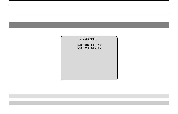
Warning displays
The warning information is displayed when |
multi cable. |
- WARNING -
CAM RCV LVL NG
CCU RCV LVL NG
●● Warning information displayed is cleared when the status returns to normal.
●● To manually clear the warning information display, hold down the [CHARA] button of the ROP.
Information displayed
Display item |
|
Description |
CAM RCV LVL NG |
The level of the optical signal received by the camera is low |
|
|
|
|
CCU RCV LVL NG |
The level of the optical signal received by the CCU is low |
|
|
|
|
CAM FAN NG |
Trouble with the cooling fan of the camera |
|
|
|
|
CCU FAN NG |
Trouble with the cooling fan of the CCU |
|
CAM HIGH TEMP |
The temperature of the camera is abnormally high |
|
|
|
|
CCU HIGH TEMP |
The temperature of the CCU is abnormally high |
|
|
If you continue operation even with the message displayed, power supply to the camera may |
|
|
stop as a protective measure. |
|
|
|
|
CAM OVER TEMP |
Due to overheating, the camera turned OFF automatically as a protective measure |
|
|
|
|
OVER LOAD |
The power supply circuit load to the camera exceeded 90% |
|
|
|
|
POWER CONT ERROR |
Trouble with the power supply circuit to the camera |
|
|
|
|
CABLE OPEN |
The optical fiber multi cable is not connected |
|
CABLE SHORT |
●● The optical fiber multi cable is shorted |
|
|
●● |
The power supply voltage to the unit dropped momentarily |
|
|
Power supply to the camera will stop as a protective measure. |
|
|
Turn the unit off immediately, and determine and resolve the problem before turning it back |
|
|
on. |
|
●● |
The camera is malfunctioning or startup of the camera failed for reasons other than the |
|
|
above. |
|
|
|
FORMAT NG |
The CAM mode and CCU mode do not match. |
|
|
|
|
During data transfer (CAM←→ROP) |
Data transfer between the camera and ROP is in progress. |
|
- 29 -

Picture monitor (PM)
IRIS display
When the information is not displayed on the picture monitor, display it by pressing the [CHARA] button of the ROP.
E E
A  C1
C1
D |
MEM:F5.6 |
F4.8 |
B |
|
------- --+---------- |
|
|
E |
C |
|
E |
A.Camera number
B.IRIS F value
C.IRIS level
D.IRIS memory
E.TALLY INFO
●● Set each item to be displayed on the [PM VIEW SETTING] screen that can be accessed by selecting [MAINTENANCE] on the CCU menu. However, this screen will not appear if the menu's [IRIS LEVEL] setting is [OFF].
●● The IRIS schedule is displayed as follows depending on the setting of [IRIS SCALE] that can be accessed by selecting [MAINTENANCE] > [SETUP].
IRIS SCALE: FULL
F4.8
C--------- |
+--------- |
O |
C:CLOSE O:OPEN
IRIS SCALE: 2STOP
•• In the IRIS level display, the IRIS F value stored in IRIS memory is indicated at the center (+), and the current IRIS F value is displayed relative to the center as " ".
".
When the center value (+) and the current IRIS value ( ) overlap, the display shows "

 ".
".
F4.8
--------- ---------
•• When the IRIS level falls outside either end of the display range, the status is displayed as a flashing " " or "
 ".
".
F4.8
----------+---------

●● TALLY INFO (E)
•• Display the R tally in two segments of the upper row and the R, G, or YL tally in two segments of the lower row.
•• When all R, G, and YL tally signals are ON, the upper row is red, and the left and right segments of the lower row are green and yellow, respectively.
•• When the R and G tally signals are ON, the upper row is red and the lower row is green.
- 30 -
 Loading...